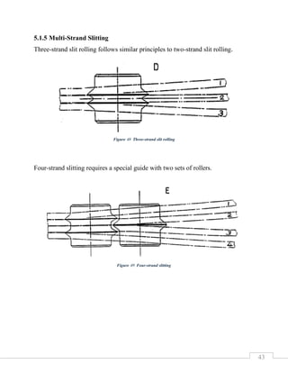
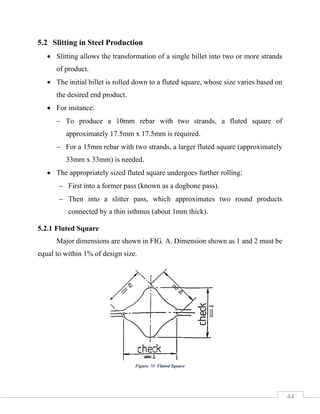
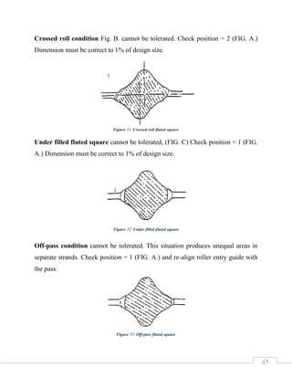
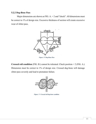
ROLLING MILLS
GUIDE
EQUIPMENT
July 2024
ADEL EZZ
Created By
1
Contents
1 Introduction........................................................................................................3
2 Entry Guides ......................................................................................................4
2.1 Stability ........................................................................................................4
2.2 Static Guides ................................................................................................5
2.3 Roller Entry Guide.......................................................................................7
2.3.1 Design of Static Inserts for Roller Entry Guides....................................10
2.3.2 '4' and '6' Roller Entry Guides - Finishing Mills ....................................13
2.3.3 Monobloc Roller Entry Guides..............................................................17
3 Delivery Guides ...............................................................................................21
3.1 Roller Delivery Guides: .............................................................................22
3.1.1 Roller Design and Adjustment: ..............................................................23
3.1.2 4 & 6 Roller Delivery Guides.................................................................24
3.2 Static Stripper Guides ................................................................................25
3.3 Rectangular Pipe or Tubular Delivery Guides:..........................................26
4 Twister Guide...................................................................................................27
4.1 Purpose of Twisters....................................................................................27
4.2 Twist Ratio and Sensitivity........................................................................28
4.3 Challenges and Considerations:.................................................................28
4.4 Twister Guide Types..................................................................................28
4.5 Materials and Design .................................................................................31
4.6 Calculation of Twist Angle Between Adjacent Stands..............................31
2
5 Working Guides...............................................................................................35
5.1 Roller Slitter Guides...................................................................................35
5.1.1 Types of Roller Slitters...........................................................................36
5.1.2 Stripper Nozzle Design...........................................................................39
5.1.3 Slitter Roller Profile................................................................................40
5.1.4 Divergence of Strands.............................................................................41
5.1.5 Multi-Strand Slitting...............................................................................43
5.2 Slitting in Steel Production ........................................................................44
5.2.1 Fluted Square ..........................................................................................44
5.2.2 Dog-Bone Pass........................................................................................46
5.2.3 Slitter Pass...............................................................................................47
5.2.4 Slitter Guide and Product Division.........................................................49
5.2.5 Advantages of Slitting ............................................................................50
References........................................................................................................51
3
1 Introduction
In hot rolling mills for long products, guide equipment guides the rolling stock
at the entry and the exit of the roll pass so as to have smooth rolling of the rolling
stock. The guiding equipment are to be sturdy, accurate and stable. Rolling mill
guide equipment play a major role in ensuring the surface quality of the rolled
product. The guides are to be designed for the wide variety of stock sizes and shapes
which are normally encountered in the long product rolling.
The categories to be discussed will fall into four main groups:
i. Entry Guides
ii. Delivery Guides
iii. Roller Twist Guides
iv. Working Guides
Figure 1 Rolling mill guide
4
2 Entry Guides
The function of an entry guides is to ensure that a bar enters the bite correctly.
The reason for using certain guides is dictated by the type of pass shape which is
being guided and the result of the reduction in the receiving pass.
2.1 Stability
Sections can be classed as stable or unstable. This means that one section
entering a pass may centralize itself whilst another section requires support to
maintain a correct relationship with the receiving pass.
For example, a diamond must be supported into a
square receiving pass and when it has been received
into the pass the nature of the reduction holds the
entering section for the remainder of the bar and the
guide could be taken away leaving the diamond
unsupported.
Figure 2 Entry Guide
Figure 3 Diamond - Square
5
Some passes automatically centralize themselves as
soon as the entering bar strikes the bite of the roll. A
round bar entering an oval pass will automatically
centralize itself in this pass. This statement should be
qualified because this centralizing tendency is
reduced as the curvature of the receiving oval is
reduced. In other words, the flatter the radius of the receiving oval the less is the
self-centralizing effect.
From this it can be understood that even self-centralizing sections require presenting
correctly to the receiving pass.
If a pass is not self-centralizing or if by virtue of the type of reduction being taken,
the section is not self-supporting, then a guide is required to direct, control and
support the material during the rolling of each bar.
2.2 Static Guides
The simplest form of entry guide is the
fabricated or cast steel trough. This is used
primarily to enter the square or rectangular
billet into the first stand and sometimes the
whole roughing group of stands, where the
product is classed as stable and only
directional control is required.
Static guides are typically made from wear-resistant materials such as tungsten
carbide, ceramics, or other hardened alloys. This durability allows them to withstand
the harsh conditions of rolling mills.
Figure 4 Round - Oval
Figure 5 Static Guide
6
Guide Shape:
• Static guides come in various shapes, including flat, V-shaped, or U-shaped
profiles.
• The choice of shape depends on the specific rolling process and the desired
product geometry.
Contact Surface:
• The guide surface that comes into direct contact with the metal stock is carefully
designed.
• It minimizes friction while maintaining stability.
• Proper surface finish ensures consistent guidance without damaging the stock.
Alignment Channels:
• Static guides often incorporate channels or grooves that guide the stock along a
predefined path.
• These channels prevent lateral deviation and ensure uniform rolling.
Advantages:
• Consistent Guidance: Static guides provide continuous and reliable guidance
throughout the rolling process.
• Reduced Edge Defects: Properly aligned static guides minimize edge cracks and
irregularities.
• Uniform Thickness: By preventing lateral movement, they contribute to
achieving uniform product thickness.
7
Disadvantages:
• Wear: Static guides experience wears due to the high temperatures and pressures
in rolling mills. Regular inspection and maintenance are essential.
• Friction: Balancing the need for stability with minimizing friction is critical.
Excessive friction can lead to surface defects.
• Material Selection: Choosing the right material for static guides involves
considering wear resistance, thermal stability, and cost-effectiveness.
2.3 Roller Entry Guide
Size of billets produced by the continuous casting process. Due to wear
experienced in the caster molds, the cast section may be as much as 10mm larger
than specified and may also be rhomboid in shape.
These variations cannot be easily
handled by the entry guide and an
adjustment must be made. Adjustments
can be very time consuming and so
guides have been developed to provide
continuous adjustment. Such a guide is
the hydraulically adjusted roller entry
guide. The roller holders are
hydraulically moved onto the incoming
bar so that the bar is gripped sufficiently to control it regardless of the amount of
"off spec" or Rhomboidity.
Figure 6 Roller Entry Guide
8
Functions of Roller Entry Guides:
1. Alignment and Positioning:
Roller entry guides ensure that the metal stock enters the rolling mill at the correct
angle and position. This initial alignment is critical for maintaining dimensional
accuracy and reducing defects in the rolled product.
2. Reduction of Misalignment Issues:
By guiding the stock precisely into the rolling stands, entry guides help prevent
common misalignment issues such as twisting, bending, and improper entry, which
can lead to uneven rolling and defects.
3. Minimization of Friction:
Entry guides reduce the friction between the metal stock and the rollers, allowing
for a smoother transition into the rolling process. This minimizes wear and tear on
both the metal stock and the rolling equipment.
4. Enhancing Process Stability:
The stability provided by roller entry guides ensures a consistent and controlled
rolling process, which is essential for producing high-quality products with uniform
dimensions and surface finish.
9
Problem experienced with the use of roller guides:
1. Misalignment of Rollers and Guides:
If the rollers and guides are not properly aligned, it can lead to uneven material
thickness and poor-quality output.
2. Bearing Failure:
The impact of the incoming bar or billet on the roller
surface and the supporting roller bearing. This exposure
can quickly damage the equipment and shorten the bearing
life considerably.
3. Wear and Tear:
Over time, rollers and guides can experience wear due to the continuous rolling
process.
Figure 7 Roller Bearing
Figure 8 Wear and tear in roller of roller guide
10
2.3.1 Design of Static Inserts for Roller Entry Guides
Static inserts play a crucial role in guiding metal bars through rolling mills,
ensuring smooth and controlled movement.
1. Long Static Inserts:
Purpose:
provide a guiding surface within the insert to control ripples or undulations in the
metal bar as it passed through to the guide rollers. Early designs often featured
long guiding surfaces within the static insert.
Application:
Commonly used when guiding after a repeater in a cross-country mill.
Advantages:
• Controlled ripples and undulations in the bar.
• Straightened the front end of the bar after the repeater curve.
• Twist in the oval or diamond did not pose significant problems.
Limitations:
• Became problematic with the introduction of interstand loopers and higher
operating speeds.
• The long guiding section acted as a brake, slowing down the bar’s progress.
• Risk of buckling out of the looper before reaching the receiving mill roll.
• Severe wear or entry cobble in close-centered horizontal stands with twist
guides.
11
2. Short Static Inserts:
Design Approach:
• Utilize large entry bellmouths leading to a short control profile.
• Protect the guide roller from heavy impaction while minimizing the control
length.
Advantages:
• Reduced braking effect, allowing smoother bar movement.
• Improved protection for guide roller collars.
• Better suited for modern mills with interstand loopers and high speeds.
Figure 9 Long Static Insert
12
In summary, modern designs favor short static inserts due to their improved
performance and reduced wear on guide components. These inserts strike a balance
between protecting the guide roller and minimizing braking effects on the bar.
Figures 9, 10 illustrate the difference between the two designs, with the path of a
twisted oval shown for each type of insert.
Figure 10 Short Static Insert
13
2.3.2 '4' and '6' Roller Entry Guides - Finishing Mills
Background:
• The ‘4’ and ‘6’ roller bar guides were initially developed for hand mills and
early cross-country mills.
• However, their usage declined significantly after the introduction of the multi-
adjustment two-roller leaf guide in the 1950s.
• These earlier guides posed challenges due to their difficulty in adjustment and
reliance on a roller bearing adjustment system involving shim packs.
• In the present day, modern mills have advanced to the point where they can
produce accurate sections at high speeds, rendering the ‘4’ and ‘6’ roller guides
obsolete.
Challenges at Higher Speeds:
Despite the benefits of increased speed, modern mills face specific challenges
related to loop control, front-end ripple, back-end lash, and loop height.
Specific Challenges and Guide Types:
• Ripple Effect:
− Ripple occurs when the front end of a bar strikes the receiving mill roll and
momentarily stops.
− The delivering mill roll continues to push the bar, creating a shockwave
within the bar.
− Small sections are particularly susceptible to this ripple effect (Figure 11).
14
• Looper Reaction:
− Looper reaction occurs when excessive loops form.
− The bar loops up against the looper delivery end (roller).
− The reaction forces the bar downward toward the looper floor or side wall
(Figure 12).
Figure 11 Ripple Effect
Figure 12 Looper reaction
15
• Back-End Lash:
− Back-end lash is a problem observed with forward-running repeaters and
180° repeaters.
− It can also occur with loopers.
− When the bar is released from the delivering mill roll, the loop collapses
suddenly.
− The bar impacts heavily against the looper floor or walls, resulting in
irregular shaping (similar to a cracked rawhide whip) (Figure 13).
Figure 13 Back-end lash
16
Role of ‘4’ and ‘6’ Roller Entry Guides:
• These guides are no longer essential for supporting the product against a turn-
down in unstable sections.
• Instead, they serve to control loop reactions and other effects at the receiving
mill roll.
• Front-end ripple can be managed using a pair of tight long-profile static inserts
and two guide rollers (Figure 11).
• However, using only two rollers with a wide-angle bellmouth and a short
control surface (Figure 12) does not effectively control looper reactions. In
such cases, the mill operator may adjust the receiving guide “off pass” slightly
to mitigate the reaction’s impact, even if it means overloading on guide roller.
Four Roller Leaf Type Guides:
• Efforts to overcome the effects of looper reactions led to the development of
four roller leaf type guides.
• These guides extend the concept of the two-roller units by adding an extra pair
of roller assemblies.
• Unfortunately, the rigidity of these designs is questionable, and the results are
not consistently successful, especially when rolling heavier products in vertical
mills.
• The primary issue lies in the flexibility of the guide leaf.
• Due to the relatively long distance from the pivot point to the front guide roll,
the leaves deflect during operation.
• As a result, only light products can be accurately guided and supported by this
type of guide.
17
2.3.3 Monobloc Roller Entry Guides
Monobloc roller entry guides are essential components used in rolling mills,
especially in conjunction with sizing mills. Sizing mills are positioned directly after
the normal finishing stand and play a crucial role in achieving precise tolerances and
surface quality for end-user requirements.
Figure 14 Four roller leaf entry guide
Figure 15 Leaf type roller guide
18
Features of Monobloc Guides:
1. Rigidity and Accuracy:
• Monobloc guides are extremely rigid and non-flexing.
• They are designed to meet the exacting standards demanded by modern bar
producers.
• The use of rigid and accurate equipment in sizing mills necessitates equally
robust roller guides on the finishing mill.
2. Roller Configurations:
• Monobloc guides come in various designs with two, four, six, or eight rollers.
• During setup, the rollers can be adjusted individually or in pairs.
• An adjuster completes the assembly, allowing simultaneous adjustment of all
rollers.
Figure 16 Monobloc type roller guide
19
3. Positioning and Nosepiece:
• Unlike leaf guides, monobloc guide rollers are positioned further away from
the mill roll bite.
• To prevent slightly bent front ends from running into the mill roll collars
(which could cause defects), a nosepiece is used.
• The nosepiece also limits back-end turn downs when small ovals are guided
by relatively large roller guides.
4. Parallelism and Settings:
• Monobloc guides allow true parallelism since there are no leaves to spring.
• Users often prefer a taper or funnel effect when setting the guide rollers.
• Roller gap relationships are critical for achieving desired results (Figures 17,
18, 19).
Figure 17 Parallel roller setting of all rollers is not necessary.
20
Figure 18 Funnel setting of rollers, back rollers are used to control looper fluctuations or reactions.
Figure 19 Funnel setting of rollers for use with 180° and 'S' type repeaters where too much restriction
may cause a premature breakout occurring.
21
5. Resilience and Wear Resistance:
• Monobloc guides lack resilience, so their components must be exceptionally
strong.
• Operating surfaces undergo extra hardening processes to reduce wear.
• Special locking mechanisms prevent vibrations from altering guide settings.
6. Entry Static and Rotary Bellmouth Effect:
• The entry static (guide surface) is very short due to the design.
• In the six-roller version, the rear pair of rollers provides a rotary bellmouth
effect.
3 Delivery Guides
Delivery guides play a critical role in guiding flat and shaped products as they
exit the rolling process. Historically, delivery guides were primarily static stripper
guides (Figure 20) or roller twist guides (Figure 21). However, recent trends,
especially in the steel industry, have led to increased interest in roller delivery
guides.
Figure 21 Roller twist guides Figure 20 Static stripper delivery guides
22
3.1 Roller Delivery Guides:
These guides serve two main purposes:
1. Reducing Surface Defects:
By using rollers, surface defects can be minimized during product delivery.
2. Controlling Twist:
• The rollers assist in controlling any tendency of the product to twist.
• This ensures that the bar is presented correctly into the next receiving stand
or delivered twist-free and longitudinally straight into the hot dividing
shears.
• The same roller designs are also useful for initiating twists in beam
sections during continuous rolling using the diagonal method.
Figure 22 Roller delivery guide in use for a track shoe section. A replaceable stripper blade is used.
23
3.1.1 Roller Design and Adjustment:
• The rollers are supported on taper roller bearings, which are sealed to prevent
ingress of scale and water.
• Adjustment is achieved using eccentric shafts.
• Bearing shafts are designed so that the detachable eccentric portion (the most
expensive part) can be separated from the rest of the assembly.
Figure 23 Exploded view of Roller Delivery guide
24
3.1.2 4 & 6 Roller Delivery Guides
• Roller entry guides for flat and structural products can also serve as delivery
guides.
• By adding a stripper guide shoe, these units provide side control for products
that may curve to one side during delivery.
• Simultaneous adjustment features enhance convenience.
Figure 24 Four Roller Entry Guide adapted as a delivery guide.
25
3.2 Static Stripper Guides
• Static stripper guides for these units feature a detachable nosepiece.
• The nosepiece is attached via a tongue and groove system.
• Helical compression springs provide a non-contact stripper function without
the need for hanging weights.
• This design balances convenience and effective stripping.
Figure 25 Striper Delivery Guide
26
3.3 Rectangular Pipe or Tubular Delivery Guides:
• Similar features of the stripper guide body and nosepiece can be adapted to
rectangular tubes.
• Cast nosepieces can provide the same benefits.
• A rocker clamp (instead of wedges) secures the strippers, avoiding potential
damage to guide rollers during installation.
Figure 26 Tubular Delivery Guides
27
4 Twister Guide
4.1 Purpose of Twisters
• Twisters are essential components in rod mills, particularly for close stand
centers (where the distance between stands is limited to a maximum of 3
meters or 9 feet).
• Their primary function is to impart twist to the bar as it passes through the
mill.
• The proximity of the twist rollers to the delivery of the mill roll ensures
efficient twisting.
Figure 27 Twister Guide
28
4.2 Twist Ratio and Sensitivity
• The ratio of twist to distance is critical. In close stand centers, the ratio is
approximately 1:4 (twist roller center to receiving guide distance).
• If used in wider stand centers (e.g., 16 feet or 4.9 meters), the ratio would
be 1:10, making the guide adjustment highly sensitive.
• Misalignment can lead to over-twisting or under-twisting errors over long
distances.
4.3 Challenges and Considerations:
• The short stripper nozzle may not effectively control the front end of the bar,
especially if misalignment occurs in the previous pass.
• Collision with the twist rollers can cause an errant bar, potentially missing the
next guide bellmouth.
• Heat generated by the bar passing through the trunnion bore poses challenges
for lubrication.
4.4 Twister Guide Types
1. Cassette Guide:
• Twister rollers are housed in a central
roller holder or cassette.
• Limited roller adjustment historically,
but improvements have been made.
• Eccentric bearing shafts allow
adjustments of up to 30mm. Figure 28 Cassette type twister with 360° of
rotation and eccentric roller adjustment of +/- 0.50"
29
2. Trunnion-Mounted Twister:
• Two roller holders (yokes) each
have their own trunnions.
• Twist angle adjustment via pressure
screws and a steel link between top
and bottom trunnions.
• A delivery nozzle is also provided in
an effort to ensure that the bar is
collected from the cantilevered rollers and produces a straight delivery to
the next stand.
Figure 30 Trunnion-Mounted Twister
Figure 29 Diagrammatic view of yoke type twister showing yokes linked together with pressure screw adjusters.
30
3. Alligator Twister
• The alligator twister guide is designed to handle extra cold or thick front
ends of rolled bars without altering the twist angle significantly.
• Its primary objective is to prevent over-twisting during the transition from
the twist rollers to the next entry guide.
• By allowing resilient movement, it avoids cobbles (bar misalignments)
caused by excessive twisting.
Mechanism:
• The guide consists of a hinged cap that carries the top roller.
• A heavy spring presses the hinged cap down against the rolled bar.
• When encountering thicker or colder bar sections, the spring allows some
flexibility, preventing abrupt changes in twist.
Figure 31 Alligator twister
Figure 32 Alligator or spring-loaded twist
guide. The spring allows cold or thick front
ends to pass through.
31
4.5 Materials and Design
• Dissimilar metals are preferred for the cassette and guide the body to
withstand heat and prevent cracking.
• Ductile iron (heat-treated to 60 tons tensile) for the cassette and stainless-steel
castings for the body and cap.
• Tightening the top cap locks the trunnion to resist turning after adjustments.
4.6 Calculation of Twist Angle Between Adjacent Stands
1. Establish Stand Centers:
• Begin by determining the distance between adjacent mill stands. This
distance plays a crucial role in calculating the twist angle.
• Consider the type of twister available:
− Inboard Type: Limited room between the guide and the mill stand
housing.
− Outboard Type: Sufficient freedom to choose any angle at the roller
holder.
2. Entry Angle Considerations:
• When twisting a bar into the next receiving guide, aim for an entry angle
(at the guide rollers) that is sensible and convenient.
• It’s not necessary to present the bar in a perfect 90° position initially.
• For example, targeting an entry angle of 80° allows the static inserts and
guide rollers to complete any additional twist required.
• Over-twisting to 90° at the guide roll is wasteful, as the bar will be over-
twisted when it reaches the roll bite.
32
3. Practical Estimation of Twist:
• Figure 33 introduces the concept of using mannequin positions on the
rolling mill floor.
• The man at the mid-stand position starts at 45°, then moves to 22.5°,
11.25°, and so on.
• By repeating these positions, you can estimate the degree of twist at the
twister rolls.
Twist Angles Derived by Method Shown Above:
Approximate angle of product at twister rollers
− Oval = 11o
− Square = 5°
Figure 33 Calculation of twist angle between adjacent stands.
33
Calculation For Above Twist Angle:
Oval:
𝑅𝑜𝑙𝑙 𝑏𝑖𝑡𝑒 𝑑𝑖𝑠𝑡𝑎𝑛𝑐𝑒 = 236 (19′
− 8′′)
𝐷𝑒𝑔𝑟𝑒𝑒𝑠 𝑝𝑒𝑟 𝑖𝑛𝑐ℎ =
90°
236
= 0.3813°
/𝑖𝑛𝑐ℎ
𝐷𝑖𝑠𝑡𝑎𝑛𝑐𝑒 𝑡𝑜 𝑡𝑤𝑖𝑠𝑡𝑒𝑟 𝑟𝑜𝑙𝑙𝑒𝑟𝑠 = 28 (2′
− 4′′)
𝑇𝑤𝑖𝑠𝑡 𝑎𝑛𝑔𝑙𝑒 𝑜𝑓 𝑝𝑟𝑜𝑑𝑢𝑐𝑡 𝑎𝑡 𝑡𝑤𝑖𝑠𝑡𝑒𝑟 𝑟𝑜𝑙𝑙𝑒𝑟𝑠 = 28 × 0.3813 = 𝟏𝟎. 𝟔𝟒°
Square:
𝑅𝑜𝑙𝑙 𝑏𝑖𝑡𝑒 𝑑𝑖𝑠𝑡𝑎𝑛𝑐𝑒 = 236 (19′
− 8′′)
𝐷𝑒𝑔𝑟𝑒𝑒𝑠 𝑝𝑒𝑟 𝑖𝑛𝑐ℎ =
45°
236
= 0.19°
/𝑖𝑛𝑐ℎ
𝐷𝑖𝑠𝑡𝑎𝑛𝑐𝑒 𝑡𝑜 𝑡𝑤𝑖𝑠𝑡𝑒𝑟 𝑟𝑜𝑙𝑙𝑒𝑟𝑠 = 28 (2′
− 4′′)
𝑇𝑤𝑖𝑠𝑡 𝑎𝑛𝑔𝑙𝑒 𝑜𝑓 𝑝𝑟𝑜𝑑𝑢𝑐𝑡 𝑎𝑡 𝑡𝑤𝑖𝑠𝑡𝑒𝑟 𝑟𝑜𝑙𝑙𝑒𝑟𝑠 = 28 × 0.19 = 𝟓. 𝟑𝟐°
Remember that these calculations and estimations are specifically for finding the
twist of the bar, not the twister setting.
34
4. Twister Roller Setting:
• To set the twister rollers accurately, follow the practical method shown in
Figure 33.
• Prepare an oval section (or obtain an accurate section from past scrap
material).
• Weld a flat bar (approximately 40mm x 6mm x 300mm) to the section
sample.
• Insert the sample section between the twist rolls in the same attitude as it
would be in the twisted position.
• Attach a simple protractor with a magnetic base to the flat portion of the
template.
• Read the correct angle directly from the protractor scale.
• Adjust the twist angle until the desired reading is obtained.
• This approach ensures a safe entry degree of twist at the receiving guide,
with room for small additional adjustments.
Figure 34 A simple setting bar for twist rollers.
Figure 35 Using a simple protractor device adjust the twister until the
correct angle is seen in the dial.
35
5 Working Guides
5.1 Roller Slitter Guides
• Roller slitter guides are among the most profitable working guides ever
produced.
• Their impact on steel production is significant, revolutionizing the way
reinforcing bars are manufactured.
• Unlike other guide developments, roller slitters have not been produced in the
same quantities, but their influence is undeniable.
Figure 36 Roller slitting guide
36
Principle of Operation:
• The key element in roller slitters is the design of the slitter roller (sometimes
referred to as the “knife”).
• Contrary to the term “knife,” the slitter’s action is not to cut the material.
• Instead, it divides sections by a wedging action, pushing them apart.
• This unique approach ensures precise slitting without actual cutting.
5.1.1 Types of Roller Slitters
1. Pizza Wheel Slitter
• Named for its resemblance to a pizza wheel, this design has limitations.
• The wheel lacks mechanical strength, and its action tends to cut through
the bar asymmetrically.
• The grooved lower wheel’s reaction causes twisting motion, leading to
rotation of the two slit rounds.
• The reduction in the leader oval pass fluctuates due to this rotation,
affecting subsequent areas in the next pass.
Figure 37 Roller slitters
37
2. Wedging Action Slitter
• A more successful design pioneered the wedging action method of slitting.
• The angle of the slitter roller is greater than the included angle of the slitter
pass.
• This difference in angles ensures effective separation of sections.
• However, this design has limitations:
− Non-adjustable bearing arrangement.
− Lack of roller adjustment (fixed roller centers).
− Smaller roller diameter (80mm) leads to high rotary speed.
− Original slitters were grease lubricated, limiting bearing life at high
speeds.
− Incorrect bearing adjustment can result in premature failure.
Figure 38 Pizza Wheel Slitter
38
3. Latest Cassette Design
• Equipped with eccentric bearing shafts for roller adjustment.
• Addresses some limitations of previous designs.
• The cassette slitter guide is secured in a holder and maintained at the
correct center position using a key.
• It can be adjusted forward or backward to accommodate varying mill roll
diameters.
• A serrated clamp system ensures that the cassette remains securely in
place.
• The slitter rolls are mounted on adjustable eccentric bearing shafts,
allowing precise adjustment of the rolls.
Figure 39 Wedging Action Slitter
39
5.1.2 Stripper Nozzle Design
• The design of the stripper nozzle varies based on the pass configuration.
• The critical feature is close control of the rolled section into the dividing
rollers.
• The internal profile should conform to the shape of the dividing pass section.
• Actual guiding should be controlled by the longitudinal groove down the
center of the bar, rather than the outside profile.
Figure 40 Cassette Slitter Guide
Figure 41 Stripper nozzle of slitting guide
40
5.1.3 Slitter Roller Profile
The roller profile affects the interference and separation of the bar sections.
Figures 42, 43 and 44 illustrate various designs of slitter roller profiles:
Example A: Original design with an included angle of 70° between the slit rounds.
Example B: More common method with an included angle of 85°, providing better
separation.
Figure 42 Slitter roller with 70° angle between the slit rounds
Figure 43 Slitter roller with 80° angle between the slit rounds
41
Example C: Unusual design with an included angle of 103° (less common).
5.1.4 Divergence of Strands
Figures 45, 46, and 47 show the shape of divided sections after passing through the
slitter guide.
The wedging action (greater than rolling action) ensures effective separation.
The original method with a 60° vee included angle in the slitter pass and a 70° angle
on the slitter roller is still in operation.
Figure 44 Slitter roller with 103° angle between the slit rounds
Figure 45 The shape of divided sections after passing through the slitter guide with 70° angle between
the slit rounds
42
The more common method uses a 60° vee included angle in the slitter pass and an
80°–85° included angle at the slitter roll. The divergence can be seen to increase
dramatically.
The divergence of the strands at 'C' is not necessary and roller wear increases due to
the "reduction" being taken.
Figure 46 The shape of divided sections after passing through the slitter guide with 85° angle between
the slit rounds
Figure 47 The shape of divided sections after passing through the slitter guide with 85° angle
between the slit rounds
43
5.1.5 Multi-Strand Slitting
Three-strand slit rolling follows similar principles to two-strand slit rolling.
Four-strand slitting requires a special guide with two sets of rollers.
Figure 48 Three-strand slit rolling
Figure 49 Four-strand slitting
44
5.2 Slitting in Steel Production
• Slitting allows the transformation of a single billet into two or more strands
of product.
• The initial billet is rolled down to a fluted square, whose size varies based on
the desired end product.
• For instance:
− To produce a 10mm rebar with two strands, a fluted square of
approximately 17.5mm x 17.5mm is required.
− For a 15mm rebar with two strands, a larger fluted square (approximately
33mm x 33mm) is needed.
• The appropriately sized fluted square undergoes further rolling:
− First into a former pass (known as a dogbone pass).
− Then into a slitter pass, which approximates two round products
connected by a thin isthmus (about 1mm thick).
5.2.1 Fluted Square
Major dimensions are shown in FIG. A. Dimension shown as 1 and 2 must be
equal to within 1% of design size.
Figure 50 Fluted Square
45
Crossed roll condition Fig. B. cannot be tolerated. Check position = 2 (FIG. A.)
Dimension must be correct to 1% of design size.
Under filled fluted square cannot be tolerated, (FIG. C) Check position = 1 (FIG.
A.) Dimension must be correct to 1% of design size.
Off-pass condition cannot be tolerated. This situation produces unequal areas in
separate strands. Check position = 1 (FIG. A.) and re-align roller entry guide with
the pass.
Figure 51 Crossed roll fluted square
Figure 52 Under filled fluted square
Figure 53 Off-pass fluted square
46
5.2.2 Dog-Bone Pass
Major dimensions are shown as FIG. A. = 2 and "check". All dimensions must
be correct to 1% of design size. Excessive thickness of section will create excessive
wear of slitter pass.
Crossed roll condition (FIG. B.) cannot be tolerated. Check position = 2 (FIG. A.)
Dimension must be correct to 1% of design size. Crossed dog-bone will damage
slitter pass severely and lead to premature failure.
Figure 54 Dog-Bone Pass
Figure 55 Crossed roll dog-bone condition
47
Off pass condition cannot be tolerated (FIG. C.) Check section visually. This
condition will create un-equal areas in separated strands causing tension in one
strand and a loop (push) in the other.
5.2.3 Slitter Pass
Major dimensions are shown in FIG. A. Dimensions shown as = 2 and "check". All
dimensions must be correct to 1% of design size.
Figure 56 Off pass bone-dog condition
Figure 57 Slitter Pass
48
Crossed roll condition (FIG.B1) cannot be tolerated. Section is more difficult to
slit. Slit section can be measured as FIG. B1 or FIG. B2.
Off pass condition (FIG.C.) cannot be tolerated. Unequal areas will be produced in
each strand. This will cause one strand to "pull" (Tension) and the other strand to
"loop" (Compression). Align entry guide on slitter pass and check entry guide and
section on dog-bone pass.
Figure 58 Crossed roll slitting pass condition
Figure 59 Off pass slitting pass condition
49
Fig. D. shows under-filled pass. This will cause tension. The underfill may be due
to incorrect roll gap (S1). If S1 is incorrect (S2) will be incorrect and strand may not
slit. S2 must always be maintained at design size of 0.7mm to 1.00mm.
5.2.4 Slitter Guide and Product Division
• After delivery from the slitter pass, the product passes through a slitter guide.
• The slitter guide divides the section into two distinct off-rounds (often referred
to as “faux rounds”).
• These two rounds are then processed in the normal manner:
− Via a leader oval.
− Followed by a finish pass.
Figure 60 under-filled slitting pass
50
5.2.5 Advantages of Slitting
• Increased Production Speed:
For a given finishing speed, production can be almost doubled compared to
other methods.
• Higher Tonnage at Slower Speeds:
Slitting allows larger tonnages to be produced even at slower finishing speeds.
• Efficient Handling and Cooling:
− Slit products can be sheared through a single dividing shear.
− Multiple bars can be fed onto a single cooling bed, simplifying logistics.
• Looper Usage:
− Loopers can eliminate tension during the process.
− They also provide a visual display of differential loop growth.
51
References
President, N. H. (n.d.). ROLLING MILL GUIDE EQUIPMENT MODERN
TRENDS II. Virginia Beach, Virginia USA: Hollteck Co. Inc.

Introduction to Types of Rolling Mills Guide Equipment

  • 1.
  • 2.
    1 Contents 1 Introduction........................................................................................................3 2 EntryGuides ......................................................................................................4 2.1 Stability ........................................................................................................4 2.2 Static Guides ................................................................................................5 2.3 Roller Entry Guide.......................................................................................7 2.3.1 Design of Static Inserts for Roller Entry Guides....................................10 2.3.2 '4' and '6' Roller Entry Guides - Finishing Mills ....................................13 2.3.3 Monobloc Roller Entry Guides..............................................................17 3 Delivery Guides ...............................................................................................21 3.1 Roller Delivery Guides: .............................................................................22 3.1.1 Roller Design and Adjustment: ..............................................................23 3.1.2 4 & 6 Roller Delivery Guides.................................................................24 3.2 Static Stripper Guides ................................................................................25 3.3 Rectangular Pipe or Tubular Delivery Guides:..........................................26 4 Twister Guide...................................................................................................27 4.1 Purpose of Twisters....................................................................................27 4.2 Twist Ratio and Sensitivity........................................................................28 4.3 Challenges and Considerations:.................................................................28 4.4 Twister Guide Types..................................................................................28 4.5 Materials and Design .................................................................................31 4.6 Calculation of Twist Angle Between Adjacent Stands..............................31
  • 3.
    2 5 Working Guides...............................................................................................35 5.1Roller Slitter Guides...................................................................................35 5.1.1 Types of Roller Slitters...........................................................................36 5.1.2 Stripper Nozzle Design...........................................................................39 5.1.3 Slitter Roller Profile................................................................................40 5.1.4 Divergence of Strands.............................................................................41 5.1.5 Multi-Strand Slitting...............................................................................43 5.2 Slitting in Steel Production ........................................................................44 5.2.1 Fluted Square ..........................................................................................44 5.2.2 Dog-Bone Pass........................................................................................46 5.2.3 Slitter Pass...............................................................................................47 5.2.4 Slitter Guide and Product Division.........................................................49 5.2.5 Advantages of Slitting ............................................................................50 References........................................................................................................51
  • 4.
    3 1 Introduction In hotrolling mills for long products, guide equipment guides the rolling stock at the entry and the exit of the roll pass so as to have smooth rolling of the rolling stock. The guiding equipment are to be sturdy, accurate and stable. Rolling mill guide equipment play a major role in ensuring the surface quality of the rolled product. The guides are to be designed for the wide variety of stock sizes and shapes which are normally encountered in the long product rolling. The categories to be discussed will fall into four main groups: i. Entry Guides ii. Delivery Guides iii. Roller Twist Guides iv. Working Guides Figure 1 Rolling mill guide
  • 5.
    4 2 Entry Guides Thefunction of an entry guides is to ensure that a bar enters the bite correctly. The reason for using certain guides is dictated by the type of pass shape which is being guided and the result of the reduction in the receiving pass. 2.1 Stability Sections can be classed as stable or unstable. This means that one section entering a pass may centralize itself whilst another section requires support to maintain a correct relationship with the receiving pass. For example, a diamond must be supported into a square receiving pass and when it has been received into the pass the nature of the reduction holds the entering section for the remainder of the bar and the guide could be taken away leaving the diamond unsupported. Figure 2 Entry Guide Figure 3 Diamond - Square
  • 6.
    5 Some passes automaticallycentralize themselves as soon as the entering bar strikes the bite of the roll. A round bar entering an oval pass will automatically centralize itself in this pass. This statement should be qualified because this centralizing tendency is reduced as the curvature of the receiving oval is reduced. In other words, the flatter the radius of the receiving oval the less is the self-centralizing effect. From this it can be understood that even self-centralizing sections require presenting correctly to the receiving pass. If a pass is not self-centralizing or if by virtue of the type of reduction being taken, the section is not self-supporting, then a guide is required to direct, control and support the material during the rolling of each bar. 2.2 Static Guides The simplest form of entry guide is the fabricated or cast steel trough. This is used primarily to enter the square or rectangular billet into the first stand and sometimes the whole roughing group of stands, where the product is classed as stable and only directional control is required. Static guides are typically made from wear-resistant materials such as tungsten carbide, ceramics, or other hardened alloys. This durability allows them to withstand the harsh conditions of rolling mills. Figure 4 Round - Oval Figure 5 Static Guide
  • 7.
    6 Guide Shape: • Staticguides come in various shapes, including flat, V-shaped, or U-shaped profiles. • The choice of shape depends on the specific rolling process and the desired product geometry. Contact Surface: • The guide surface that comes into direct contact with the metal stock is carefully designed. • It minimizes friction while maintaining stability. • Proper surface finish ensures consistent guidance without damaging the stock. Alignment Channels: • Static guides often incorporate channels or grooves that guide the stock along a predefined path. • These channels prevent lateral deviation and ensure uniform rolling. Advantages: • Consistent Guidance: Static guides provide continuous and reliable guidance throughout the rolling process. • Reduced Edge Defects: Properly aligned static guides minimize edge cracks and irregularities. • Uniform Thickness: By preventing lateral movement, they contribute to achieving uniform product thickness.
  • 8.
    7 Disadvantages: • Wear: Staticguides experience wears due to the high temperatures and pressures in rolling mills. Regular inspection and maintenance are essential. • Friction: Balancing the need for stability with minimizing friction is critical. Excessive friction can lead to surface defects. • Material Selection: Choosing the right material for static guides involves considering wear resistance, thermal stability, and cost-effectiveness. 2.3 Roller Entry Guide Size of billets produced by the continuous casting process. Due to wear experienced in the caster molds, the cast section may be as much as 10mm larger than specified and may also be rhomboid in shape. These variations cannot be easily handled by the entry guide and an adjustment must be made. Adjustments can be very time consuming and so guides have been developed to provide continuous adjustment. Such a guide is the hydraulically adjusted roller entry guide. The roller holders are hydraulically moved onto the incoming bar so that the bar is gripped sufficiently to control it regardless of the amount of "off spec" or Rhomboidity. Figure 6 Roller Entry Guide
  • 9.
    8 Functions of RollerEntry Guides: 1. Alignment and Positioning: Roller entry guides ensure that the metal stock enters the rolling mill at the correct angle and position. This initial alignment is critical for maintaining dimensional accuracy and reducing defects in the rolled product. 2. Reduction of Misalignment Issues: By guiding the stock precisely into the rolling stands, entry guides help prevent common misalignment issues such as twisting, bending, and improper entry, which can lead to uneven rolling and defects. 3. Minimization of Friction: Entry guides reduce the friction between the metal stock and the rollers, allowing for a smoother transition into the rolling process. This minimizes wear and tear on both the metal stock and the rolling equipment. 4. Enhancing Process Stability: The stability provided by roller entry guides ensures a consistent and controlled rolling process, which is essential for producing high-quality products with uniform dimensions and surface finish.
  • 10.
    9 Problem experienced withthe use of roller guides: 1. Misalignment of Rollers and Guides: If the rollers and guides are not properly aligned, it can lead to uneven material thickness and poor-quality output. 2. Bearing Failure: The impact of the incoming bar or billet on the roller surface and the supporting roller bearing. This exposure can quickly damage the equipment and shorten the bearing life considerably. 3. Wear and Tear: Over time, rollers and guides can experience wear due to the continuous rolling process. Figure 7 Roller Bearing Figure 8 Wear and tear in roller of roller guide
  • 11.
    10 2.3.1 Design ofStatic Inserts for Roller Entry Guides Static inserts play a crucial role in guiding metal bars through rolling mills, ensuring smooth and controlled movement. 1. Long Static Inserts: Purpose: provide a guiding surface within the insert to control ripples or undulations in the metal bar as it passed through to the guide rollers. Early designs often featured long guiding surfaces within the static insert. Application: Commonly used when guiding after a repeater in a cross-country mill. Advantages: • Controlled ripples and undulations in the bar. • Straightened the front end of the bar after the repeater curve. • Twist in the oval or diamond did not pose significant problems. Limitations: • Became problematic with the introduction of interstand loopers and higher operating speeds. • The long guiding section acted as a brake, slowing down the bar’s progress. • Risk of buckling out of the looper before reaching the receiving mill roll. • Severe wear or entry cobble in close-centered horizontal stands with twist guides.
  • 12.
    11 2. Short StaticInserts: Design Approach: • Utilize large entry bellmouths leading to a short control profile. • Protect the guide roller from heavy impaction while minimizing the control length. Advantages: • Reduced braking effect, allowing smoother bar movement. • Improved protection for guide roller collars. • Better suited for modern mills with interstand loopers and high speeds. Figure 9 Long Static Insert
  • 13.
    12 In summary, moderndesigns favor short static inserts due to their improved performance and reduced wear on guide components. These inserts strike a balance between protecting the guide roller and minimizing braking effects on the bar. Figures 9, 10 illustrate the difference between the two designs, with the path of a twisted oval shown for each type of insert. Figure 10 Short Static Insert
  • 14.
    13 2.3.2 '4' and'6' Roller Entry Guides - Finishing Mills Background: • The ‘4’ and ‘6’ roller bar guides were initially developed for hand mills and early cross-country mills. • However, their usage declined significantly after the introduction of the multi- adjustment two-roller leaf guide in the 1950s. • These earlier guides posed challenges due to their difficulty in adjustment and reliance on a roller bearing adjustment system involving shim packs. • In the present day, modern mills have advanced to the point where they can produce accurate sections at high speeds, rendering the ‘4’ and ‘6’ roller guides obsolete. Challenges at Higher Speeds: Despite the benefits of increased speed, modern mills face specific challenges related to loop control, front-end ripple, back-end lash, and loop height. Specific Challenges and Guide Types: • Ripple Effect: − Ripple occurs when the front end of a bar strikes the receiving mill roll and momentarily stops. − The delivering mill roll continues to push the bar, creating a shockwave within the bar. − Small sections are particularly susceptible to this ripple effect (Figure 11).
  • 15.
    14 • Looper Reaction: −Looper reaction occurs when excessive loops form. − The bar loops up against the looper delivery end (roller). − The reaction forces the bar downward toward the looper floor or side wall (Figure 12). Figure 11 Ripple Effect Figure 12 Looper reaction
  • 16.
    15 • Back-End Lash: −Back-end lash is a problem observed with forward-running repeaters and 180° repeaters. − It can also occur with loopers. − When the bar is released from the delivering mill roll, the loop collapses suddenly. − The bar impacts heavily against the looper floor or walls, resulting in irregular shaping (similar to a cracked rawhide whip) (Figure 13). Figure 13 Back-end lash
  • 17.
    16 Role of ‘4’and ‘6’ Roller Entry Guides: • These guides are no longer essential for supporting the product against a turn- down in unstable sections. • Instead, they serve to control loop reactions and other effects at the receiving mill roll. • Front-end ripple can be managed using a pair of tight long-profile static inserts and two guide rollers (Figure 11). • However, using only two rollers with a wide-angle bellmouth and a short control surface (Figure 12) does not effectively control looper reactions. In such cases, the mill operator may adjust the receiving guide “off pass” slightly to mitigate the reaction’s impact, even if it means overloading on guide roller. Four Roller Leaf Type Guides: • Efforts to overcome the effects of looper reactions led to the development of four roller leaf type guides. • These guides extend the concept of the two-roller units by adding an extra pair of roller assemblies. • Unfortunately, the rigidity of these designs is questionable, and the results are not consistently successful, especially when rolling heavier products in vertical mills. • The primary issue lies in the flexibility of the guide leaf. • Due to the relatively long distance from the pivot point to the front guide roll, the leaves deflect during operation. • As a result, only light products can be accurately guided and supported by this type of guide.
  • 18.
    17 2.3.3 Monobloc RollerEntry Guides Monobloc roller entry guides are essential components used in rolling mills, especially in conjunction with sizing mills. Sizing mills are positioned directly after the normal finishing stand and play a crucial role in achieving precise tolerances and surface quality for end-user requirements. Figure 14 Four roller leaf entry guide Figure 15 Leaf type roller guide
  • 19.
    18 Features of MonoblocGuides: 1. Rigidity and Accuracy: • Monobloc guides are extremely rigid and non-flexing. • They are designed to meet the exacting standards demanded by modern bar producers. • The use of rigid and accurate equipment in sizing mills necessitates equally robust roller guides on the finishing mill. 2. Roller Configurations: • Monobloc guides come in various designs with two, four, six, or eight rollers. • During setup, the rollers can be adjusted individually or in pairs. • An adjuster completes the assembly, allowing simultaneous adjustment of all rollers. Figure 16 Monobloc type roller guide
  • 20.
    19 3. Positioning andNosepiece: • Unlike leaf guides, monobloc guide rollers are positioned further away from the mill roll bite. • To prevent slightly bent front ends from running into the mill roll collars (which could cause defects), a nosepiece is used. • The nosepiece also limits back-end turn downs when small ovals are guided by relatively large roller guides. 4. Parallelism and Settings: • Monobloc guides allow true parallelism since there are no leaves to spring. • Users often prefer a taper or funnel effect when setting the guide rollers. • Roller gap relationships are critical for achieving desired results (Figures 17, 18, 19). Figure 17 Parallel roller setting of all rollers is not necessary.
  • 21.
    20 Figure 18 Funnelsetting of rollers, back rollers are used to control looper fluctuations or reactions. Figure 19 Funnel setting of rollers for use with 180° and 'S' type repeaters where too much restriction may cause a premature breakout occurring.
  • 22.
    21 5. Resilience andWear Resistance: • Monobloc guides lack resilience, so their components must be exceptionally strong. • Operating surfaces undergo extra hardening processes to reduce wear. • Special locking mechanisms prevent vibrations from altering guide settings. 6. Entry Static and Rotary Bellmouth Effect: • The entry static (guide surface) is very short due to the design. • In the six-roller version, the rear pair of rollers provides a rotary bellmouth effect. 3 Delivery Guides Delivery guides play a critical role in guiding flat and shaped products as they exit the rolling process. Historically, delivery guides were primarily static stripper guides (Figure 20) or roller twist guides (Figure 21). However, recent trends, especially in the steel industry, have led to increased interest in roller delivery guides. Figure 21 Roller twist guides Figure 20 Static stripper delivery guides
  • 23.
    22 3.1 Roller DeliveryGuides: These guides serve two main purposes: 1. Reducing Surface Defects: By using rollers, surface defects can be minimized during product delivery. 2. Controlling Twist: • The rollers assist in controlling any tendency of the product to twist. • This ensures that the bar is presented correctly into the next receiving stand or delivered twist-free and longitudinally straight into the hot dividing shears. • The same roller designs are also useful for initiating twists in beam sections during continuous rolling using the diagonal method. Figure 22 Roller delivery guide in use for a track shoe section. A replaceable stripper blade is used.
  • 24.
    23 3.1.1 Roller Designand Adjustment: • The rollers are supported on taper roller bearings, which are sealed to prevent ingress of scale and water. • Adjustment is achieved using eccentric shafts. • Bearing shafts are designed so that the detachable eccentric portion (the most expensive part) can be separated from the rest of the assembly. Figure 23 Exploded view of Roller Delivery guide
  • 25.
    24 3.1.2 4 &6 Roller Delivery Guides • Roller entry guides for flat and structural products can also serve as delivery guides. • By adding a stripper guide shoe, these units provide side control for products that may curve to one side during delivery. • Simultaneous adjustment features enhance convenience. Figure 24 Four Roller Entry Guide adapted as a delivery guide.
  • 26.
    25 3.2 Static StripperGuides • Static stripper guides for these units feature a detachable nosepiece. • The nosepiece is attached via a tongue and groove system. • Helical compression springs provide a non-contact stripper function without the need for hanging weights. • This design balances convenience and effective stripping. Figure 25 Striper Delivery Guide
  • 27.
    26 3.3 Rectangular Pipeor Tubular Delivery Guides: • Similar features of the stripper guide body and nosepiece can be adapted to rectangular tubes. • Cast nosepieces can provide the same benefits. • A rocker clamp (instead of wedges) secures the strippers, avoiding potential damage to guide rollers during installation. Figure 26 Tubular Delivery Guides
  • 28.
    27 4 Twister Guide 4.1Purpose of Twisters • Twisters are essential components in rod mills, particularly for close stand centers (where the distance between stands is limited to a maximum of 3 meters or 9 feet). • Their primary function is to impart twist to the bar as it passes through the mill. • The proximity of the twist rollers to the delivery of the mill roll ensures efficient twisting. Figure 27 Twister Guide
  • 29.
    28 4.2 Twist Ratioand Sensitivity • The ratio of twist to distance is critical. In close stand centers, the ratio is approximately 1:4 (twist roller center to receiving guide distance). • If used in wider stand centers (e.g., 16 feet or 4.9 meters), the ratio would be 1:10, making the guide adjustment highly sensitive. • Misalignment can lead to over-twisting or under-twisting errors over long distances. 4.3 Challenges and Considerations: • The short stripper nozzle may not effectively control the front end of the bar, especially if misalignment occurs in the previous pass. • Collision with the twist rollers can cause an errant bar, potentially missing the next guide bellmouth. • Heat generated by the bar passing through the trunnion bore poses challenges for lubrication. 4.4 Twister Guide Types 1. Cassette Guide: • Twister rollers are housed in a central roller holder or cassette. • Limited roller adjustment historically, but improvements have been made. • Eccentric bearing shafts allow adjustments of up to 30mm. Figure 28 Cassette type twister with 360° of rotation and eccentric roller adjustment of +/- 0.50"
  • 30.
    29 2. Trunnion-Mounted Twister: •Two roller holders (yokes) each have their own trunnions. • Twist angle adjustment via pressure screws and a steel link between top and bottom trunnions. • A delivery nozzle is also provided in an effort to ensure that the bar is collected from the cantilevered rollers and produces a straight delivery to the next stand. Figure 30 Trunnion-Mounted Twister Figure 29 Diagrammatic view of yoke type twister showing yokes linked together with pressure screw adjusters.
  • 31.
    30 3. Alligator Twister •The alligator twister guide is designed to handle extra cold or thick front ends of rolled bars without altering the twist angle significantly. • Its primary objective is to prevent over-twisting during the transition from the twist rollers to the next entry guide. • By allowing resilient movement, it avoids cobbles (bar misalignments) caused by excessive twisting. Mechanism: • The guide consists of a hinged cap that carries the top roller. • A heavy spring presses the hinged cap down against the rolled bar. • When encountering thicker or colder bar sections, the spring allows some flexibility, preventing abrupt changes in twist. Figure 31 Alligator twister Figure 32 Alligator or spring-loaded twist guide. The spring allows cold or thick front ends to pass through.
  • 32.
    31 4.5 Materials andDesign • Dissimilar metals are preferred for the cassette and guide the body to withstand heat and prevent cracking. • Ductile iron (heat-treated to 60 tons tensile) for the cassette and stainless-steel castings for the body and cap. • Tightening the top cap locks the trunnion to resist turning after adjustments. 4.6 Calculation of Twist Angle Between Adjacent Stands 1. Establish Stand Centers: • Begin by determining the distance between adjacent mill stands. This distance plays a crucial role in calculating the twist angle. • Consider the type of twister available: − Inboard Type: Limited room between the guide and the mill stand housing. − Outboard Type: Sufficient freedom to choose any angle at the roller holder. 2. Entry Angle Considerations: • When twisting a bar into the next receiving guide, aim for an entry angle (at the guide rollers) that is sensible and convenient. • It’s not necessary to present the bar in a perfect 90° position initially. • For example, targeting an entry angle of 80° allows the static inserts and guide rollers to complete any additional twist required. • Over-twisting to 90° at the guide roll is wasteful, as the bar will be over- twisted when it reaches the roll bite.
  • 33.
    32 3. Practical Estimationof Twist: • Figure 33 introduces the concept of using mannequin positions on the rolling mill floor. • The man at the mid-stand position starts at 45°, then moves to 22.5°, 11.25°, and so on. • By repeating these positions, you can estimate the degree of twist at the twister rolls. Twist Angles Derived by Method Shown Above: Approximate angle of product at twister rollers − Oval = 11o − Square = 5° Figure 33 Calculation of twist angle between adjacent stands.
  • 34.
    33 Calculation For AboveTwist Angle: Oval: 𝑅𝑜𝑙𝑙 𝑏𝑖𝑡𝑒 𝑑𝑖𝑠𝑡𝑎𝑛𝑐𝑒 = 236 (19′ − 8′′) 𝐷𝑒𝑔𝑟𝑒𝑒𝑠 𝑝𝑒𝑟 𝑖𝑛𝑐ℎ = 90° 236 = 0.3813° /𝑖𝑛𝑐ℎ 𝐷𝑖𝑠𝑡𝑎𝑛𝑐𝑒 𝑡𝑜 𝑡𝑤𝑖𝑠𝑡𝑒𝑟 𝑟𝑜𝑙𝑙𝑒𝑟𝑠 = 28 (2′ − 4′′) 𝑇𝑤𝑖𝑠𝑡 𝑎𝑛𝑔𝑙𝑒 𝑜𝑓 𝑝𝑟𝑜𝑑𝑢𝑐𝑡 𝑎𝑡 𝑡𝑤𝑖𝑠𝑡𝑒𝑟 𝑟𝑜𝑙𝑙𝑒𝑟𝑠 = 28 × 0.3813 = 𝟏𝟎. 𝟔𝟒° Square: 𝑅𝑜𝑙𝑙 𝑏𝑖𝑡𝑒 𝑑𝑖𝑠𝑡𝑎𝑛𝑐𝑒 = 236 (19′ − 8′′) 𝐷𝑒𝑔𝑟𝑒𝑒𝑠 𝑝𝑒𝑟 𝑖𝑛𝑐ℎ = 45° 236 = 0.19° /𝑖𝑛𝑐ℎ 𝐷𝑖𝑠𝑡𝑎𝑛𝑐𝑒 𝑡𝑜 𝑡𝑤𝑖𝑠𝑡𝑒𝑟 𝑟𝑜𝑙𝑙𝑒𝑟𝑠 = 28 (2′ − 4′′) 𝑇𝑤𝑖𝑠𝑡 𝑎𝑛𝑔𝑙𝑒 𝑜𝑓 𝑝𝑟𝑜𝑑𝑢𝑐𝑡 𝑎𝑡 𝑡𝑤𝑖𝑠𝑡𝑒𝑟 𝑟𝑜𝑙𝑙𝑒𝑟𝑠 = 28 × 0.19 = 𝟓. 𝟑𝟐° Remember that these calculations and estimations are specifically for finding the twist of the bar, not the twister setting.
  • 35.
    34 4. Twister RollerSetting: • To set the twister rollers accurately, follow the practical method shown in Figure 33. • Prepare an oval section (or obtain an accurate section from past scrap material). • Weld a flat bar (approximately 40mm x 6mm x 300mm) to the section sample. • Insert the sample section between the twist rolls in the same attitude as it would be in the twisted position. • Attach a simple protractor with a magnetic base to the flat portion of the template. • Read the correct angle directly from the protractor scale. • Adjust the twist angle until the desired reading is obtained. • This approach ensures a safe entry degree of twist at the receiving guide, with room for small additional adjustments. Figure 34 A simple setting bar for twist rollers. Figure 35 Using a simple protractor device adjust the twister until the correct angle is seen in the dial.
  • 36.
    35 5 Working Guides 5.1Roller Slitter Guides • Roller slitter guides are among the most profitable working guides ever produced. • Their impact on steel production is significant, revolutionizing the way reinforcing bars are manufactured. • Unlike other guide developments, roller slitters have not been produced in the same quantities, but their influence is undeniable. Figure 36 Roller slitting guide
  • 37.
    36 Principle of Operation: •The key element in roller slitters is the design of the slitter roller (sometimes referred to as the “knife”). • Contrary to the term “knife,” the slitter’s action is not to cut the material. • Instead, it divides sections by a wedging action, pushing them apart. • This unique approach ensures precise slitting without actual cutting. 5.1.1 Types of Roller Slitters 1. Pizza Wheel Slitter • Named for its resemblance to a pizza wheel, this design has limitations. • The wheel lacks mechanical strength, and its action tends to cut through the bar asymmetrically. • The grooved lower wheel’s reaction causes twisting motion, leading to rotation of the two slit rounds. • The reduction in the leader oval pass fluctuates due to this rotation, affecting subsequent areas in the next pass. Figure 37 Roller slitters
  • 38.
    37 2. Wedging ActionSlitter • A more successful design pioneered the wedging action method of slitting. • The angle of the slitter roller is greater than the included angle of the slitter pass. • This difference in angles ensures effective separation of sections. • However, this design has limitations: − Non-adjustable bearing arrangement. − Lack of roller adjustment (fixed roller centers). − Smaller roller diameter (80mm) leads to high rotary speed. − Original slitters were grease lubricated, limiting bearing life at high speeds. − Incorrect bearing adjustment can result in premature failure. Figure 38 Pizza Wheel Slitter
  • 39.
    38 3. Latest CassetteDesign • Equipped with eccentric bearing shafts for roller adjustment. • Addresses some limitations of previous designs. • The cassette slitter guide is secured in a holder and maintained at the correct center position using a key. • It can be adjusted forward or backward to accommodate varying mill roll diameters. • A serrated clamp system ensures that the cassette remains securely in place. • The slitter rolls are mounted on adjustable eccentric bearing shafts, allowing precise adjustment of the rolls. Figure 39 Wedging Action Slitter
  • 40.
    39 5.1.2 Stripper NozzleDesign • The design of the stripper nozzle varies based on the pass configuration. • The critical feature is close control of the rolled section into the dividing rollers. • The internal profile should conform to the shape of the dividing pass section. • Actual guiding should be controlled by the longitudinal groove down the center of the bar, rather than the outside profile. Figure 40 Cassette Slitter Guide Figure 41 Stripper nozzle of slitting guide
  • 41.
    40 5.1.3 Slitter RollerProfile The roller profile affects the interference and separation of the bar sections. Figures 42, 43 and 44 illustrate various designs of slitter roller profiles: Example A: Original design with an included angle of 70° between the slit rounds. Example B: More common method with an included angle of 85°, providing better separation. Figure 42 Slitter roller with 70° angle between the slit rounds Figure 43 Slitter roller with 80° angle between the slit rounds
  • 42.
    41 Example C: Unusualdesign with an included angle of 103° (less common). 5.1.4 Divergence of Strands Figures 45, 46, and 47 show the shape of divided sections after passing through the slitter guide. The wedging action (greater than rolling action) ensures effective separation. The original method with a 60° vee included angle in the slitter pass and a 70° angle on the slitter roller is still in operation. Figure 44 Slitter roller with 103° angle between the slit rounds Figure 45 The shape of divided sections after passing through the slitter guide with 70° angle between the slit rounds
  • 43.
    42 The more commonmethod uses a 60° vee included angle in the slitter pass and an 80°–85° included angle at the slitter roll. The divergence can be seen to increase dramatically. The divergence of the strands at 'C' is not necessary and roller wear increases due to the "reduction" being taken. Figure 46 The shape of divided sections after passing through the slitter guide with 85° angle between the slit rounds Figure 47 The shape of divided sections after passing through the slitter guide with 85° angle between the slit rounds
  • 44.
    43 5.1.5 Multi-Strand Slitting Three-strandslit rolling follows similar principles to two-strand slit rolling. Four-strand slitting requires a special guide with two sets of rollers. Figure 48 Three-strand slit rolling Figure 49 Four-strand slitting
  • 45.
    44 5.2 Slitting inSteel Production • Slitting allows the transformation of a single billet into two or more strands of product. • The initial billet is rolled down to a fluted square, whose size varies based on the desired end product. • For instance: − To produce a 10mm rebar with two strands, a fluted square of approximately 17.5mm x 17.5mm is required. − For a 15mm rebar with two strands, a larger fluted square (approximately 33mm x 33mm) is needed. • The appropriately sized fluted square undergoes further rolling: − First into a former pass (known as a dogbone pass). − Then into a slitter pass, which approximates two round products connected by a thin isthmus (about 1mm thick). 5.2.1 Fluted Square Major dimensions are shown in FIG. A. Dimension shown as 1 and 2 must be equal to within 1% of design size. Figure 50 Fluted Square
  • 46.
    45 Crossed roll conditionFig. B. cannot be tolerated. Check position = 2 (FIG. A.) Dimension must be correct to 1% of design size. Under filled fluted square cannot be tolerated, (FIG. C) Check position = 1 (FIG. A.) Dimension must be correct to 1% of design size. Off-pass condition cannot be tolerated. This situation produces unequal areas in separate strands. Check position = 1 (FIG. A.) and re-align roller entry guide with the pass. Figure 51 Crossed roll fluted square Figure 52 Under filled fluted square Figure 53 Off-pass fluted square
  • 47.
    46 5.2.2 Dog-Bone Pass Majordimensions are shown as FIG. A. = 2 and "check". All dimensions must be correct to 1% of design size. Excessive thickness of section will create excessive wear of slitter pass. Crossed roll condition (FIG. B.) cannot be tolerated. Check position = 2 (FIG. A.) Dimension must be correct to 1% of design size. Crossed dog-bone will damage slitter pass severely and lead to premature failure. Figure 54 Dog-Bone Pass Figure 55 Crossed roll dog-bone condition
  • 48.
    47 Off pass conditioncannot be tolerated (FIG. C.) Check section visually. This condition will create un-equal areas in separated strands causing tension in one strand and a loop (push) in the other. 5.2.3 Slitter Pass Major dimensions are shown in FIG. A. Dimensions shown as = 2 and "check". All dimensions must be correct to 1% of design size. Figure 56 Off pass bone-dog condition Figure 57 Slitter Pass
  • 49.
    48 Crossed roll condition(FIG.B1) cannot be tolerated. Section is more difficult to slit. Slit section can be measured as FIG. B1 or FIG. B2. Off pass condition (FIG.C.) cannot be tolerated. Unequal areas will be produced in each strand. This will cause one strand to "pull" (Tension) and the other strand to "loop" (Compression). Align entry guide on slitter pass and check entry guide and section on dog-bone pass. Figure 58 Crossed roll slitting pass condition Figure 59 Off pass slitting pass condition
  • 50.
    49 Fig. D. showsunder-filled pass. This will cause tension. The underfill may be due to incorrect roll gap (S1). If S1 is incorrect (S2) will be incorrect and strand may not slit. S2 must always be maintained at design size of 0.7mm to 1.00mm. 5.2.4 Slitter Guide and Product Division • After delivery from the slitter pass, the product passes through a slitter guide. • The slitter guide divides the section into two distinct off-rounds (often referred to as “faux rounds”). • These two rounds are then processed in the normal manner: − Via a leader oval. − Followed by a finish pass. Figure 60 under-filled slitting pass
  • 51.
    50 5.2.5 Advantages ofSlitting • Increased Production Speed: For a given finishing speed, production can be almost doubled compared to other methods. • Higher Tonnage at Slower Speeds: Slitting allows larger tonnages to be produced even at slower finishing speeds. • Efficient Handling and Cooling: − Slit products can be sheared through a single dividing shear. − Multiple bars can be fed onto a single cooling bed, simplifying logistics. • Looper Usage: − Loopers can eliminate tension during the process. − They also provide a visual display of differential loop growth.
  • 52.
    51 References President, N. H.(n.d.). ROLLING MILL GUIDE EQUIPMENT MODERN TRENDS II. Virginia Beach, Virginia USA: Hollteck Co. Inc.