Download as PDF, PPTX


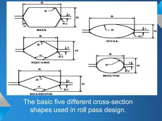
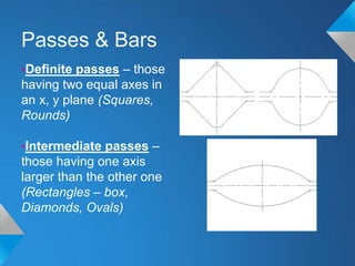
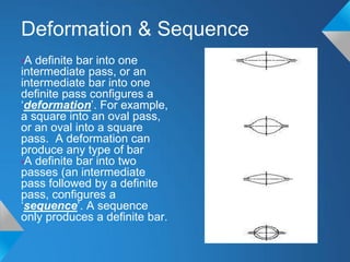
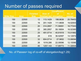
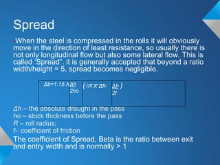
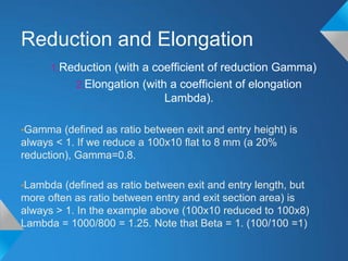
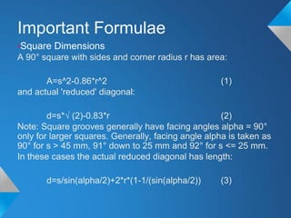
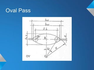
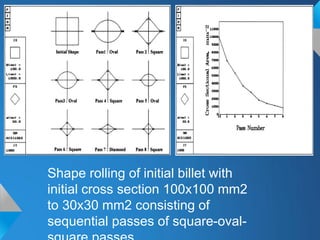
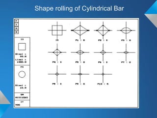


The document discusses roll pass design for continuous bar mills. It defines basic terminology like roll pass and nominal roll gap. The goal of roll pass design is to produce the desired product shape with good internal structure, surface and lowest cost. There are definite, intermediate and combination pass shapes. A deformation changes one shape to another, while a sequence produces a definite shape. Roll pass design considers the starting material, mill layout, sizes, power and production needs to determine pass details, schedules and power requirements for each pass. It also discusses basic rolling laws and formulas for shapes like squares and ovals.


