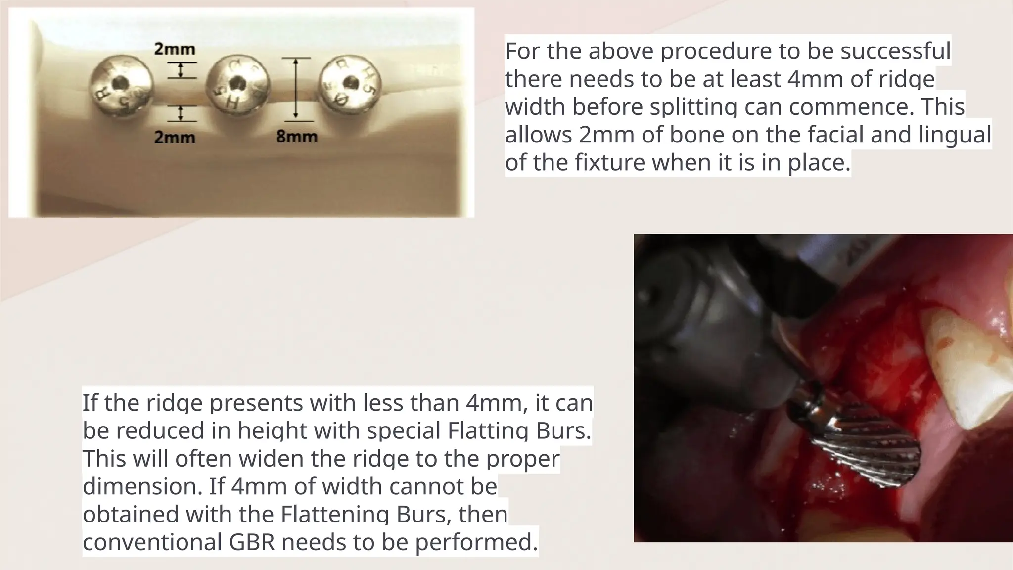
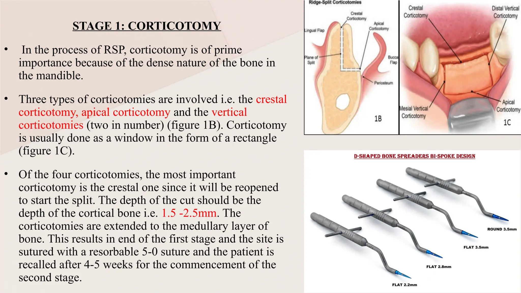
RIDGE SPLIT TECHNIQUES
DR. SATVIKA PRASAD
MDS
DEPT. OF PROSTHODONTICS
CONTENTS
• Introduction
• History
• Indication
• Contraindications
• Site specific
indications
• Advantages
• Disadvantages
• Classification
• Types of devices used
• Concept of bone
collapse & resorption
• Surgical principles of
ridge split procedure
• Types of ridge split
procedure
• Concept of bone
expansion
• Complication
• Recent advancement-
flapless technique
• Conclusion
• References
INTRODUCTION
Ridge resorption after teeth loss is an obvious,
unpredictable, and continuous process. Such narrow,
atrophic alveolar ridges pose a challenge and greater
difficulty for successful restoratively driven implant
placement as a tooth replacement option
Several methods have been implicated to augment the
narrow alveolar ridge, such as guided bone regeneration
(GBR) using various graft materials (autograft,
allograft, xenograft, and alloplast), autogenous onlay
block grafts harvested intra-orally or extra-orally,
distraction osteogenesis, ridge expansion osteotomy, and
ridge splitting
The ridge slit procedure is a bone manipulation technique
used to place implants in sites having bucco-lingual
deficiencies. The objective is to achieve at least 1-1.5mm
of healthy bone labial and palatal to the implant, which
will provide long-term support to soft tissue.
RIDGE EXPANSION TECHNIQUE :- Introduced by Tatum in 1986
Modified by Summers in 1994
By the means of hand osteotomes with gradually increasing dimensions
Designed an implant system (Omni R system; Florida) for this technique
RIDGE SPLITTING TECHNIQUE :- by Simion et al in 1992
A longitudinal ridge splitting in 2 parts, provoking a GREENSTICK fracture by
means of small chisels
PRE- REQUISITES:
A Minimum width of 3-4 mm
Only in soft bone quality (type III or IV)
HISTORY
INDICATIONS FOR RIDGE EXPANSION
• For implant placement or inter-positional bone graft
placement
• Narrow alveolar ridge (minimum 3 mm, marrow component)
• Primarily maxillary sites greater than one tooth
• If in mandible, only posterior distal extension edentulous
sites with a marrow component
• Adequate alveolar bone height (approx. 10 mm minimum)
CONTRAINDICATIONS FOR RIDGE
EXPANSION
• Inadequate alveolar bone height
• Concavities or undercuts of ridge
• Fused cortices (no marrow)
• Less than 2mm ridge width
• Single tooth sites
1. ≥ 2mm of horizontal bone thickness at crest
2. ≥ 10mm of vertical bone height to vital structures
3. Non concave cross sectional anatomy
4. Corticotomies must remain 1mm away from adjacent teeth
5. Most preferably molars single tooth site
SITE SPECIFIC INDICATIONS
ADVANTAGES
• It provides shorter treatment period in comparison to conventional
bone graft techniques. Since it does not require a waiting period of
4-6 months for bone consolidation prior to implant placement
• It decreases the morbidity and complication rates since it avoids a
second surgical donor site for bone harvesting
• Also allows the installation of implants in the same surgery
• Reposition cortical bone around implants
• Decreased cost
DISADVANTAGES
• Can only increase the bucco-lingual bony dimension.
• Is not applicable if there is insufficient bone height for implant
placement
• If implemented on atrophic ridges less than 3mm wide- may
result in unfavorable bone fractures that lead to bone resorption
• Can be applied only when the buccal and palatal/ lingual plates
are separated by spongy bone
• Unfavorable buccal inclination of implants placed in expanded
areas
Tolstunov L. Classification of the alveolar ridge width: implant-driven treatment considerations for the horizontally deficient alveolar ridges. Journal of Oral Implantology. 2014 Jul 1;40(S1):365-
70.
Traditional
devices
Chisel and hand
mallet
* Modified to
chisel and
electronic mallet
Osteotomes
Surgical burs
Modern
devices
Motorized
ridge
expander
Threaded bone
expanders
Expansion crest
device
Laser
Ultrasonic /
piezoelectric
devices
Types of devices used
CONCEPT OF BONE COLLAPSE AND BONE RESORPTION
• Before going ahead with the ridge split procedure (RSP), it is important to
understand the difference between bone resorption and bone collapse that
defines bone deficiency in a particular region.
• On extraction of single or multiple teeth, the cancellous or spongy bone
undergoes bone resorption. But the cortical bone undergoes collapse resulting in
loss of function or stability (fig. 1A)
• This leads to buccal and lingual cortical plate lying proximal to each other with
minimal amount of medullary bone within it. In case of extraction that includes
trauma, both cortical and medullary bone loss occurs together resulting in a true
corticomedullary bone loss.
• Thus , the ideal cases for a ridge split procedure includes a mild medullary bone
resorption with mild to moderate loss of cortical bone and an alveolar width
ranging from 3 to 5mm having a good alveolar height.
• It is very difficult to separate two proximal cortical plates with very little
interpositional medullary bone.
• The medullary bone is the area where the actual split occurs. Therefore, more the
amount of interpositional medullary bone, easier it is to split the cortical plates
and more predictable results can be expected. On flattening the coronal bone a
SURGICAL PRINCIPLES OF RIDGE SPLIT PROCEDURE
(RSP)
1. Development of a vascular bone flap.
2. Healing mostly occurs by the
secondary intention.#
3. Osteocondensation is one of the
processes by which healing occurs.*
4. Osteomobilization of cortical plates.
5. Healing occurs differently in maxilla
and mandible
• Primary closure of the surgical
wound results in a full
approximation of its edges.
• Secondary closure (closure or
healing by secondary
intention) leaves the surgical
wound open and relies on a
potential of the wound edges
to grow and the wound to
eventually heal (close) with a
scar formation.
In the process of bone manipulation
during the RSP, the adjacent fragments
of bone are slightly compressed or
condensed.
#
*
Surgical procedure
• Full thickness crestal incision with vertical releasing incisions on
tooth further than the site being treated
• Elevation of mucoperiosteal flap palatally and buccally to expose
the bone ridge.
• Lamellar cortical splitting initiated one horizontal crestal osteotomy
using a diamond disk, bur or preferably a piezo surgery tip.
• The longitudinal split can be limited by placing transverse cuts in
the bone. 2 additional vertical cuts, 2mm distal to the site of
implantation and 1mm mesial to the adjacent teeth, can be
performed to facilitate the expansion. It can be performed using a
set of chisels of increasing width. They are optimally used by
pressing the instrument manually into the bone or by gently tapping
the chisels with a hammer.
• Normally the chisels are extended to a depth of 5-7mm, but the
penetration depends on the width of the ridge.
• Facial- lingual movement should be avoided so as not to further
deform the buccal plate
• The gap is created by splitting, can be filled with different materials such as
collagen sponge, autogenous bone chips or bone substitutes. The split ridge
can be covered with membranes.
• Dental implant placement at the same time or later according to a standard
procedure. There is a lack of evidence for delayed Implant placement when
using the ridge split technique.
• When placed immediately, primary stability is achieved by placing the
implants at the most apical non fractured portion of the jawbone. To improve
primary stability of the implants and to prevent fracture of the buccal plate,
the use of osteotomes to prepare the implant bed is recommended.
• Wound closure with vertical mattress sutures.
• Dental rehabilitation may be started 3-6 months afterwards.
Tolstunov L. Surgical Principles of the Ridge Split Procedure. Horizontal Alveolar Ridge Augmentation in Implant Dentistry: A Surgical Manual. 2016 Jan 4:185-91.
‐
• During ridge expansion the buccal cortical plate is separated
from the underlying medullary or spongy bone and is moved
buccally (labially, in anterior cases).
• The buccal cortical bone fragment is attached to the periosteum
and, thus, is vascularized. This partially or fully detached
fragment of the buccal portion of the alveolar ridge is
repositioned laterally (rotated or moved).
• The amount of movement can be different and is dictated by
many functional and esthetic factors.
• As discussed above, a vascularized intraoral hard–soft tissue
buccal flap can be developed either as a book rotating about its
base (binder) in a hinged manner (still connected to its base, like
a greenstick fracture), called a “book flap”, or
• Be fully separated (disconnected from the “mother” bony
fragment) from its bony base (free-floating) but still connected
to the soft tissue called an “island flap”.
Osteomobilization of the buccal bone
A crestal incision with vertical release is made and a
full thickness flap reflected, exposing the bone
A narrow diameter drill prepares minimal osteotomy,
defining fixture placement and trajectory
Either a piezotome with a flat cutting tip, or an implant handpiece
with a circular saw blade is used to cut into the occlusal aspect of
the ridge to a depth of 8-10mm
Special Expansion Burs, are used at 30 rpm, to
slowly spread the facial bone to allow implants to
be placed into the newly expanded ridge. The
vertical bone cuts facilitate this facial movement of
the bony plate.
In addition, two vertical cuts, 4-5mm long and 2-3mm
deep are made on the facial of the ridge, mesial and
distal to the occlusal cut, and intersecting with it.
After sufficient integration of about 2 months in the
mandible and 4 months in the maxilla, second stage
surgery is performed and the restoration phase
begins.
For the above procedure to be successful
there needs to be at least 4mm of ridge
width before splitting can commence. This
allows 2mm of bone on the facial and lingual
of the fixture when it is in place.
If the ridge presents with less than 4mm, it can
be reduced in height with special Flatting Burs.
This will often widen the ridge to the proper
dimension. If 4mm of width cannot be
obtained with the Flattening Burs, then
conventional GBR needs to be performed.
TYPES OF RIDGE SPLIT PROCEDURE
ONE
STAGE
TWO
STAGE
THREE
STAGE
MAXILLARY SINGLE-STAGE ALVEOLAR
RIDGE-SPLIT PROCEDURE
Maxilla is composed mostly of spongy or the cancellous bone which is soft in nature.
Therefore in maxilla, a crestal corticotomy along with limited vertical corticotomies
are required with a split thickness flap which comprise the single stage approach
MANDIBULAR TWO-STAGE ALVEOLAR
RIDGE-SPLIT PROCEDURE
STAGE 1: CORTICOTOMY
STAGE 2: SPLITTING, EXPANSION, AND GRAFTING
Elian N, Jalbout Z, Ehrlich B, Classi A, Cho SC, Al-Kahtani F, Froum S, Tarnow DP. A two-stage full-arch ridge expansion technique: review of the literature and clinical guidelines. Implant
Dentistry. 2008 Mar 1;17(1):16-23.
STAGE 1: CORTICOTOMY
• In the process of RSP, corticotomy is of prime
importance because of the dense nature of the bone in
the mandible.
• Three types of corticotomies are involved i.e. the crestal
corticotomy, apical corticotomy and the vertical
corticotomies (two in number) (figure 1B). Corticotomy
is usually done as a window in the form of a rectangle
(figure 1C).
• Of the four corticotomies, the most important
corticotomy is the crestal one since it will be reopened
to start the split. The depth of the cut should be the
depth of the cortical bone i.e. 1.5 -2.5mm. The
corticotomies are extended to the medullary layer of
bone. This results in end of the first stage and the site is
sutured with a resorbable 5-0 suture and the patient is
recalled after 4-5 weeks for the commencement of the
second stage.
STAGE 2: SPLITTING, EXPANSION, AND GRAFTING
In this stage, Osteomobilization is done by splitting the bone along
the medullary bone leading to the movement of the bone buccally by
forward movement. If in the stage 1, the buccal bone has been
evenly weakened throughout then the Osteomobilization becomes
easy. Therefore, they cause movement with the help of special
osteotomes and spreaders.
SURGICAL PROCEDURE
The second stage of the surgery should be started only with a crestal
incision (figure 1D).
Buccal periosteal vascularization is maintained by prevention of
reflection of the flap
Partial thickness flap could be used to allow visibility as well as to
maintain the vascularization of the bone that is to be splitted (figure
1E)
Splitting, expansion of bone is done
GRAFTING –
• The most ideal grafting material would be the one that maintains the split during the time of healing and provide
osteoconduction. Xenografts like Puros, AlloOss, Bio-Oss and Nu-Oss can be used (figure 2B).
• Once the graft has been assimilated, the graft needs to be isolated from the oral environment by the usage of barrier
membranes.
• Non resorbable membrane would require a surgical re-entry for its removal while resorbable doesn’t.
• However, a resorbable membrane interferes with the tissue healing and predictable outcome. After desired placement of
membrane, suture is given. (figure 2C)
THREE STAGE SPLIT CREST TECHNIQUE
(HU ET AL 2008)
• Hu et al in 2008 came up with a three stage procedure for the split crest technique.
• In the first stage, only corticotomy is done following mid crestal incision and
reflection. It ends with primary flap closure and the patient is recalled after 2-3
months.
• In the second stage, a split crest knife is used to give an incision at the crest to
only view the ridge crest or a limited full thickness flap. Then particulate bone graft
is placed in the interpositional gap and then suture is placed with primary closure.
• In the third stage, patient is recalled after 4-6 months for implant placement
Hu GH, Froum SJ, Alodadi A, Nose F, Yu YC, Suzuki T, Cho SC. A Three-Stage Split-Crest Technique: Case Series of Horizontal Ridge Augmentation in the Atrophic Posterior Mandible.
International Journal of Periodontics & Restorative Dentistry. 2018 Jul 1;38(4).
ALVEOLAR RIDGE SPLIT TECHNIQUE
USING PIEZOSURGERY (Moro et al 2017)
• Vercelotti et al 2000 introduced the use of piezoelectric surgery in the
treatment of atrophic jaw.
• The advantage of using piezosurgery is that it is -
 Safer,
 Easier and
 Decrease the complications that are encountered when done with
osteotomes.
Vercellotti T. Piezoelectric surgery in implantology: a case report--a new piezoelectric ridge expansion technique. International Journal of Periodontics & Restorative Dentistry. 2000 Aug 1;20(4).
Moro A, Gasparini G, Foresta E, Saponaro G, Falchi M, Cardarelli L, De Angelis P, Forcione M, Garagiola U, D’Amato G, Pelo S. Alveolar ridge split technique using piezosurgery with specially designed tips.
BioMed research international. 2017;2017(1):4530378.
• Use of piezosurgery reported no cases of
infection and post operative complication.
• This study has used various kinds of piezo
tips for the comfortable cutting of the bone.
• The first set of tips that were used in this
study was the square shaped tips which had
the advantage of performing the
osteotomies faster and efficiently (figure
3A, 3B)
• The second set that were used in this study
were with blunt edges that had the
advantage of being less aggressive to avoid
damage to vital structures. After splitting of
alveolar bone, desired bone graft is placed
along with suitable membrane (figure 3C).
APICAL U-SHAPE SPLITTING TECHNIQUE(WU ET AL
IN 2019)
• In the anterior maxilla, ridge splitting technique with immediate loading is preferable.
• There are many advantages to this technique that includes less use of -
 bone substitute,
 immediate loading and
 usage of the cancellous bone for fracture less bone spreading.
• More the cancellous bone, better outcome can be predicted.
• During RST, splitting of the bone segment might result in greenstick fracture of the segment due to the
concavity owing to its pattern of resorption.
• The principle for U shape splitting concentrates on expanding the thinnest area or the most concave area
leaving alveolar crest alone.
Wu Q, Yang B, Gao S, Gong P, Xiang L, Man Y, Qu Y. Apical U-shape splitting technique for undercut areas of the anterior alveolar ridge: a prospective non-randomized controlled study. International Journal
of Oral and Maxillofacial Surgery. 2019 Mar 1;48(3):388-94.
SURGICAL PROCEDURE
• Mucoperiosteal flap is reflected for the bone able to be seen. In this procedure, bone is scored in a U shape till the
cancellous bone.
• The osteotomy is done just above the lower portion of the concavity to the depth of the cancellous bone. The
vertical osteotomy was done 1 mm of the adjacent roots and the cuts are extended beyond the undercuts.
• Then, the released bone end was gently leveled out using a periosteotome through a greenstick fracture so as to
create enough space for implant placement. Following which an immediate implant placement can be done (fig.4)
Wu et al in 2018 reported that the use apical U shape split procedure resulted in greater
ridge width gain in comparison to GBR technique
ADVANTAGES
• its ability to maintain the space
DISADVANATGES -
• Deeper defects resulted in jeopardizing the bone flap and the elevation is not possible
in that case.
• Deeper defect resulted in thinner bone flap which resorbs faster due to lack of blood
supply. Therefore, this technique holds well for the less deep defects
CONCEPT OF BONE EXPANSION
One of the most important complications of implant dentistry is the
atrophic ridge in the maxilla. Narrow crests make it difficult for the
placement of implants which led to discovery of ridge expansion
procedures.
Summers in 1994 first introduced the expansion osteotomes which
were cylindrical and conical in shape. The shape of the instrument
explains a lot about the mechanism by which bone expansion in maxilla
occurs.
Summers expansion osteotomes are cylindrical-conical in shape with
steady escalation of the instrument diameter wherein the base of each
instrument corresponds to the active part of the next one. (figure 5A.)
SUMMERS R. A new concept in maxillary implant surgery. The osteotome technique Compendium. 1994;15:158.
BONE SPREADING TECHNIQUE (BST)
(Nishioka et al 2010)
• This technique is basically an alternative Summers osteotomy technique
which involves less trauma to the bone while expanding it followed by
implant placement. Screw spreaders are used with increasing diameters to
expand the bone laterally (figure 5 B, C)
• The first thing that needs to be understood is that the maxilla is composed of
less dense bone and more of spongy bone and trabecular bone.
• Nishioka et al suggested that this technique was feasible for the patients with
a spongy bone width of 2.5mm between the cortical walls. This technique
allows the clinicians for implant placement in areas where the bone thickness
is very less. It has a control system that controls the horizontal dimension to a
certain width and also prevents excessive expansion of the medullary bone.
Nishioka RS, Souza FA. Bone spreader technique: a preliminary 3-year study. Journal of Oral Implantology. 2009 Dec 1;35(6):289-94.
SPLIT-CREST TECHNIQUE
• This technique uses the piezo surgery device and the
ultrasonic bone surgery device to make precise cuts and
osteotomies for splitting the alveolar crest giving more
predictable outcome.
• Piezoelectric transducers have more energy in terms of
bone cutting. Piezo-electric materials when subjected to
intense electric field, typically in the 500–750 V/mm range.
Rationale –
• Trauma that is caused to the bone due to the use of
chisels. In the mandible, the stresses are more due to the
presence of dense bone. Therefore the use of oscillating
instruments is effectual and less strenuous on the patient.
Blus C, Szmukler Moncler S. Split crest and immediate implant placement with ultra sonic bone surgery: a 3 year life table analysis with 230 treated sites. Clinical Oral Implants Research. 2006 Dec;17(6):700-7.
‐ ‐ ‐ ‐ ‐
EXTENSION CREST TECHNIQUE
Chiapasco et al suggested the
use of a new device in 2006
called as the extension crest
device (fig. 6 A, B). It was
anticipated to be used for the
sagittal osteotomy in case of
atrophied ridge. The extension
crest device provides a slow and
steady expansion of the sagittal
osteotomy and also reduces the
risk of the buccal plate fracture.
Chiapasco M, Ferrini F, Casentini P, Accardi S, Zaniboni M. Dental implants placed in expanded narrow edentulous ridges with the Extension Crest® device: A 1–3 year multicenter follow up study. Clinical Oral Implants Research. 2006
‐ ‐
Jun;17(3):265-72.
COMPLICATIONS
• Basal greenstick fracture of the segments during widening has not been
controllable to date. Thus, fracture of the buccal palate is the most common
complication. Care must be taken in the presence of undercuts that may
increase the risk of bone fracture. A minimum width of 2-3mm of the
coronal alveolar crest is necessary to avoid bone fracture.
• Loosening or fracture of implants may happen
• A labyrinth concussion or subluxation of adjacent tooth may occur during
tapping of an osteotome
• Patient may experience a Benign Paroxysmal Positional Vertigo (BPPV)
• Neurosensory complication in case of nerve
damage(Rare)
An innovative computer guided ridge
splitting flapless technique with
simultaneous implant placement: A
case report
Dohiem M, Khorshid HE, Zekry KA. An innovative computer guided ridge splitting flapless technique with simultaneous implant placement: a case report. Future Dental Journal. 2018 Jun
1;4(1):16-22.
II. CBCT Acquisition
The patient’s maxilla was radiographed using Cone Beam
Computed Tomographic (CBCT) which revealed bone
width of about 3.54 mm and bone height of about 16mm in
the first premolar region which indicated the necessity of
alveolar ridge splitting in the first premolar region.
I. Pre-surgical Preparation:
The pre-surgical preparation required the construction of
conventional maxillary partial denture. And then duplication of
the partial denture using heat cured clear acrylic resin was
performed. After adequate finishing and polishing of the
radiographic template, 2mm channels were drilled through the
stent at the centers of the teeth with the proposed implant
placement.
1. External Box: is a hollowed rectangular shaped box with an outer
dimension of 7x5x8mm and 1mm in thickness. There was also a 0.5
mm internal ledge created 1mm away from the top aspect of the box.
This Box will accommodate the box shaped guides (Fig.2E).
2. Blade Guide: is a rectangular shaped box that fits precisely into the
External Box. Its upper aspect has an external ledge that will
precisely fit the ledge on the inner aspect of the box. It contains an
internal slit that is 0.5mm in width and that will exactly fit the blade
tip (Fig.2A).
3. Blade Handle Guide: is a rectangular shaped box that fits precisely
into the External Box. Its upper aspect has an external ledge that will
precisely fit the ledge on the inner aspect of the box. It contains an
internal slit that is 2.6mm in width and that will exactly fit the lancet
blade handle (Fig.2C).
III. Designing the Guide Tools:
The second step involved a series of creating and designing special 3D virtual guide slits and boxes that can accommodate and
precisely fit the tools used for the ridge splitting technique
4. Split Chisel Guide: is a rectangular shaped box that fits
precisely into the External Box. Its upper aspect has an
external ledge that will precisely fit the ledge on the inner
aspect of the box. It contains an internal slit that is 1.7 mm
in width and that will exactly fit the Split bone chisel
(Fig.2B).
5. Internal splitting plane: the rationale behind this plane was
to facilitate the visibility of the direction of entry within
bone thus used as a virtual planning tool (Fig.2G).
6. Drill Implant Sleeve Guide: is a rectangular shaped box
that fits precisely into the External Box. Its upper aspect
has an external ledge that will precisely fit the ledge on the
inner aspect of the box. This guide contains no slits as the
supra-bony portion of the virtual implant model will be
minused from this box thus creating the implant guide
sleeve (Fig.2D)
IV. The Virtual Stent Fabrication:
All the guides were exported as STL
(Stereolithographic) files to a 3D printing
machine (Invision Si2, USA) to build the
stent from a photo curable resin material.
V. The Surgical Procedure:
The stent was checked for adequate stability and fit and then
fixed in place using a small amount of flowable composite
injected onto the fitting surface of the anterior part of the
stent opposing the natural teeth then cured while the patient
was biting on the silicon interocclusal index (Fig.4).
The Blade guide was then replaced by the Blade handle guide
allowing the handle and blade to pass through the slit until a
predetermined depth of 9mm was reached (Fig.5). The blade handle
guide was then replaced by the Chisel guide (Fig.6) and the Bone Split
Chisel was progressively driven deeper in the crestal osteotomy using
a mallet provoking a flapless split or fracture of the buccal plate of the
bone (Fig.7)
VI. Implant Placement:
The Chisel guide was then replaced by the
Implant guide sleeve and implants were
placed.
After 3 months patient was recalled and CBCT
and ISQ(implant stability quotient) reading
were made and ISQ readings were 69 &
measurements were made of the
buccolingual bone width.
The total amount of bucco-lingual bone width
was 3.54mm preoperatively while reached
5.6mm postoperatively
They concluded, due to the computer guided, flapless, alveolar
ridge splitting technique, the periosteum preservation helped
maintain an adequate blood supply to the split buccal plate of
bone, stabilized the ridge split fracture and reduced the
resorption rate of the bony plates. For the alveolar ridge with
insufficient thickness but adequate height, this computer
guided flapless alveolar ridge splitting technique can be a
predictable, less invasive, an atraumatic technique and a viable
treatment option when immediate implant placement is a
prerequisite and minimized treatment time is required.
CONCLUSION
• Ridge split techniques represent a valuable option for managing
narrow alveolar ridges in implant dentistry.
• These techniques offer the advantages of minimal invasiveness,
reduced morbidity, and shortened treatment times compared to
more extensive bone grafting procedures.
• However, careful patient selection and precise surgical execution
are crucial to mitigate potential complications and ensure optimal
results.
• Further studies with long-term follow-up are needed to confirm the
durability and predictability of this technique
References
1. Das M, Das AC, Panda S, Nayak R, Mohanty R, Satpathy A. Ridge Split Techniques: A Literature Review. Indian
Journal of Forensic Medicine & Toxicology. 2021 Apr 1;15(2):3847.
2. Tolstunov L. Classification of the alveolar ridge width: implant-driven treatment considerations for the horizontally
deficient alveolar ridges. Journal of Oral Implantology. 2014 Jul 1;40(S1):365-70.
3. Tolstunov L. Surgical Principles of the Ridge Split Procedure. Horizontal Alveolar Ridge Augmentation in Implant
‐
Dentistry: A Surgical Manual. 2016 Jan 4:185-91.
4. Elian N, Jalbout Z, Ehrlich B, Classi A, Cho SC, Al-Kahtani F, Froum S, Tarnow DP. A two-stage full-arch ridge
expansion technique: review of the literature and clinical guidelines. Implant Dentistry. 2008 Mar 1;17(1):16-23.
5. Hu GH, Froum SJ, Alodadi A, Nose F, Yu YC, Suzuki T, Cho SC. A Three-Stage Split-Crest Technique: Case Series
of Horizontal Ridge Augmentation in the Atrophic Posterior Mandible. International Journal of Periodontics &
Restorative Dentistry. 2018 Jul 1;38(4).
6. Moro A, Gasparini G, Foresta E, Saponaro G, Falchi M, Cardarelli L, De Angelis P, Forcione M, Garagiola U,
D’Amato G, Pelo S. Alveolar ridge split technique using piezosurgery with specially designed tips. BioMed research
international. 2017;2017(1):4530378.
7. Wu Q, Yang B, Gao S, Gong P, Xiang L, Man Y, Qu Y. Apical U-shape splitting technique for undercut areas of the
anterior alveolar ridge: a prospective non-randomized controlled study. International Journal of Oral and
Maxillofacial Surgery. 2019 Mar 1;48(3):388-94.
8. SUMMERS R. A new concept in maxillary implant surgery. The osteotome technique Compendium. 1994;15:158.
9. Nishioka RS, Souza FA. Bone spreader technique: a preliminary 3-year study. Journal of Oral Implantology. 2009
Dec 1;35(6):289-94.
10. Blus C, Szmukler Moncler S. Split crest and immediate implant placement with ultra sonic bone surgery: a 3 year
‐ ‐ ‐ ‐
life table analysis with 230 treated sites. Clinical Oral Implants Research. 2006 Dec;17(6):700-7.
‐
11. Chiapasco M, Ferrini F, Casentini P, Accardi S, Zaniboni M. Dental implants placed in expanded narrow edentulous
ridges with the Extension Crest® device: A 1–3 year multicenter follow up study. Clinical Oral Implants Research.
‐ ‐
2006 Jun;17(3):265-72.
12. Duncan JM, Westwood RM. Ridge widening for the thin maxilla: a clinical report. Int J Oral Maxillofac Implants.
1997 Apr;12(2):224–7.
13. González-García R, Monje F, Moreno C. Alveolar split osteotomy for the treatment of the severe narrow ridge
maxillary atrophy: a modified technique. Int J Oral Maxillofac Surg. 2011 Jan;40(1):57–64.
14. Dohiem M, Khorshid HE, Zekry KA. An innovative computer guided ridge splitting flapless technique with
simultaneous implant placement: a case report. Future Dental Journal. 2018 Jun 1;4(1):16-22.

Ridge Split Techniques in Prosthodontics: Enhancing Alveolar Ridge for Successful Implant Placement

  • 1.
    RIDGE SPLIT TECHNIQUES DR.SATVIKA PRASAD MDS DEPT. OF PROSTHODONTICS
  • 2.
    CONTENTS • Introduction • History •Indication • Contraindications • Site specific indications • Advantages • Disadvantages • Classification • Types of devices used • Concept of bone collapse & resorption • Surgical principles of ridge split procedure • Types of ridge split procedure • Concept of bone expansion • Complication • Recent advancement- flapless technique • Conclusion • References
  • 3.
    INTRODUCTION Ridge resorption afterteeth loss is an obvious, unpredictable, and continuous process. Such narrow, atrophic alveolar ridges pose a challenge and greater difficulty for successful restoratively driven implant placement as a tooth replacement option Several methods have been implicated to augment the narrow alveolar ridge, such as guided bone regeneration (GBR) using various graft materials (autograft, allograft, xenograft, and alloplast), autogenous onlay block grafts harvested intra-orally or extra-orally, distraction osteogenesis, ridge expansion osteotomy, and ridge splitting The ridge slit procedure is a bone manipulation technique used to place implants in sites having bucco-lingual deficiencies. The objective is to achieve at least 1-1.5mm of healthy bone labial and palatal to the implant, which will provide long-term support to soft tissue.
  • 4.
    RIDGE EXPANSION TECHNIQUE:- Introduced by Tatum in 1986 Modified by Summers in 1994 By the means of hand osteotomes with gradually increasing dimensions Designed an implant system (Omni R system; Florida) for this technique RIDGE SPLITTING TECHNIQUE :- by Simion et al in 1992 A longitudinal ridge splitting in 2 parts, provoking a GREENSTICK fracture by means of small chisels PRE- REQUISITES: A Minimum width of 3-4 mm Only in soft bone quality (type III or IV) HISTORY
  • 5.
    INDICATIONS FOR RIDGEEXPANSION • For implant placement or inter-positional bone graft placement • Narrow alveolar ridge (minimum 3 mm, marrow component) • Primarily maxillary sites greater than one tooth • If in mandible, only posterior distal extension edentulous sites with a marrow component • Adequate alveolar bone height (approx. 10 mm minimum)
  • 6.
    CONTRAINDICATIONS FOR RIDGE EXPANSION •Inadequate alveolar bone height • Concavities or undercuts of ridge • Fused cortices (no marrow) • Less than 2mm ridge width • Single tooth sites
  • 7.
    1. ≥ 2mmof horizontal bone thickness at crest 2. ≥ 10mm of vertical bone height to vital structures 3. Non concave cross sectional anatomy 4. Corticotomies must remain 1mm away from adjacent teeth 5. Most preferably molars single tooth site SITE SPECIFIC INDICATIONS
  • 8.
    ADVANTAGES • It providesshorter treatment period in comparison to conventional bone graft techniques. Since it does not require a waiting period of 4-6 months for bone consolidation prior to implant placement • It decreases the morbidity and complication rates since it avoids a second surgical donor site for bone harvesting • Also allows the installation of implants in the same surgery • Reposition cortical bone around implants • Decreased cost
  • 9.
    DISADVANTAGES • Can onlyincrease the bucco-lingual bony dimension. • Is not applicable if there is insufficient bone height for implant placement • If implemented on atrophic ridges less than 3mm wide- may result in unfavorable bone fractures that lead to bone resorption • Can be applied only when the buccal and palatal/ lingual plates are separated by spongy bone • Unfavorable buccal inclination of implants placed in expanded areas
  • 10.
    Tolstunov L. Classificationof the alveolar ridge width: implant-driven treatment considerations for the horizontally deficient alveolar ridges. Journal of Oral Implantology. 2014 Jul 1;40(S1):365- 70.
  • 11.
    Traditional devices Chisel and hand mallet *Modified to chisel and electronic mallet Osteotomes Surgical burs Modern devices Motorized ridge expander Threaded bone expanders Expansion crest device Laser Ultrasonic / piezoelectric devices Types of devices used
  • 12.
    CONCEPT OF BONECOLLAPSE AND BONE RESORPTION • Before going ahead with the ridge split procedure (RSP), it is important to understand the difference between bone resorption and bone collapse that defines bone deficiency in a particular region. • On extraction of single or multiple teeth, the cancellous or spongy bone undergoes bone resorption. But the cortical bone undergoes collapse resulting in loss of function or stability (fig. 1A) • This leads to buccal and lingual cortical plate lying proximal to each other with minimal amount of medullary bone within it. In case of extraction that includes trauma, both cortical and medullary bone loss occurs together resulting in a true corticomedullary bone loss. • Thus , the ideal cases for a ridge split procedure includes a mild medullary bone resorption with mild to moderate loss of cortical bone and an alveolar width ranging from 3 to 5mm having a good alveolar height. • It is very difficult to separate two proximal cortical plates with very little interpositional medullary bone. • The medullary bone is the area where the actual split occurs. Therefore, more the amount of interpositional medullary bone, easier it is to split the cortical plates and more predictable results can be expected. On flattening the coronal bone a
  • 13.
    SURGICAL PRINCIPLES OFRIDGE SPLIT PROCEDURE (RSP) 1. Development of a vascular bone flap. 2. Healing mostly occurs by the secondary intention.# 3. Osteocondensation is one of the processes by which healing occurs.* 4. Osteomobilization of cortical plates. 5. Healing occurs differently in maxilla and mandible • Primary closure of the surgical wound results in a full approximation of its edges. • Secondary closure (closure or healing by secondary intention) leaves the surgical wound open and relies on a potential of the wound edges to grow and the wound to eventually heal (close) with a scar formation. In the process of bone manipulation during the RSP, the adjacent fragments of bone are slightly compressed or condensed. # *
  • 14.
    Surgical procedure • Fullthickness crestal incision with vertical releasing incisions on tooth further than the site being treated • Elevation of mucoperiosteal flap palatally and buccally to expose the bone ridge. • Lamellar cortical splitting initiated one horizontal crestal osteotomy using a diamond disk, bur or preferably a piezo surgery tip. • The longitudinal split can be limited by placing transverse cuts in the bone. 2 additional vertical cuts, 2mm distal to the site of implantation and 1mm mesial to the adjacent teeth, can be performed to facilitate the expansion. It can be performed using a set of chisels of increasing width. They are optimally used by pressing the instrument manually into the bone or by gently tapping the chisels with a hammer. • Normally the chisels are extended to a depth of 5-7mm, but the penetration depends on the width of the ridge. • Facial- lingual movement should be avoided so as not to further deform the buccal plate
  • 15.
    • The gapis created by splitting, can be filled with different materials such as collagen sponge, autogenous bone chips or bone substitutes. The split ridge can be covered with membranes. • Dental implant placement at the same time or later according to a standard procedure. There is a lack of evidence for delayed Implant placement when using the ridge split technique. • When placed immediately, primary stability is achieved by placing the implants at the most apical non fractured portion of the jawbone. To improve primary stability of the implants and to prevent fracture of the buccal plate, the use of osteotomes to prepare the implant bed is recommended. • Wound closure with vertical mattress sutures. • Dental rehabilitation may be started 3-6 months afterwards. Tolstunov L. Surgical Principles of the Ridge Split Procedure. Horizontal Alveolar Ridge Augmentation in Implant Dentistry: A Surgical Manual. 2016 Jan 4:185-91. ‐
  • 16.
    • During ridgeexpansion the buccal cortical plate is separated from the underlying medullary or spongy bone and is moved buccally (labially, in anterior cases). • The buccal cortical bone fragment is attached to the periosteum and, thus, is vascularized. This partially or fully detached fragment of the buccal portion of the alveolar ridge is repositioned laterally (rotated or moved). • The amount of movement can be different and is dictated by many functional and esthetic factors. • As discussed above, a vascularized intraoral hard–soft tissue buccal flap can be developed either as a book rotating about its base (binder) in a hinged manner (still connected to its base, like a greenstick fracture), called a “book flap”, or • Be fully separated (disconnected from the “mother” bony fragment) from its bony base (free-floating) but still connected to the soft tissue called an “island flap”. Osteomobilization of the buccal bone
  • 17.
    A crestal incisionwith vertical release is made and a full thickness flap reflected, exposing the bone A narrow diameter drill prepares minimal osteotomy, defining fixture placement and trajectory Either a piezotome with a flat cutting tip, or an implant handpiece with a circular saw blade is used to cut into the occlusal aspect of the ridge to a depth of 8-10mm
  • 18.
    Special Expansion Burs,are used at 30 rpm, to slowly spread the facial bone to allow implants to be placed into the newly expanded ridge. The vertical bone cuts facilitate this facial movement of the bony plate. In addition, two vertical cuts, 4-5mm long and 2-3mm deep are made on the facial of the ridge, mesial and distal to the occlusal cut, and intersecting with it. After sufficient integration of about 2 months in the mandible and 4 months in the maxilla, second stage surgery is performed and the restoration phase begins.
  • 19.
    For the aboveprocedure to be successful there needs to be at least 4mm of ridge width before splitting can commence. This allows 2mm of bone on the facial and lingual of the fixture when it is in place. If the ridge presents with less than 4mm, it can be reduced in height with special Flatting Burs. This will often widen the ridge to the proper dimension. If 4mm of width cannot be obtained with the Flattening Burs, then conventional GBR needs to be performed.
  • 20.
    TYPES OF RIDGESPLIT PROCEDURE ONE STAGE TWO STAGE THREE STAGE
  • 21.
    MAXILLARY SINGLE-STAGE ALVEOLAR RIDGE-SPLITPROCEDURE Maxilla is composed mostly of spongy or the cancellous bone which is soft in nature. Therefore in maxilla, a crestal corticotomy along with limited vertical corticotomies are required with a split thickness flap which comprise the single stage approach
  • 23.
    MANDIBULAR TWO-STAGE ALVEOLAR RIDGE-SPLITPROCEDURE STAGE 1: CORTICOTOMY STAGE 2: SPLITTING, EXPANSION, AND GRAFTING Elian N, Jalbout Z, Ehrlich B, Classi A, Cho SC, Al-Kahtani F, Froum S, Tarnow DP. A two-stage full-arch ridge expansion technique: review of the literature and clinical guidelines. Implant Dentistry. 2008 Mar 1;17(1):16-23.
  • 24.
    STAGE 1: CORTICOTOMY •In the process of RSP, corticotomy is of prime importance because of the dense nature of the bone in the mandible. • Three types of corticotomies are involved i.e. the crestal corticotomy, apical corticotomy and the vertical corticotomies (two in number) (figure 1B). Corticotomy is usually done as a window in the form of a rectangle (figure 1C). • Of the four corticotomies, the most important corticotomy is the crestal one since it will be reopened to start the split. The depth of the cut should be the depth of the cortical bone i.e. 1.5 -2.5mm. The corticotomies are extended to the medullary layer of bone. This results in end of the first stage and the site is sutured with a resorbable 5-0 suture and the patient is recalled after 4-5 weeks for the commencement of the second stage.
  • 25.
    STAGE 2: SPLITTING,EXPANSION, AND GRAFTING In this stage, Osteomobilization is done by splitting the bone along the medullary bone leading to the movement of the bone buccally by forward movement. If in the stage 1, the buccal bone has been evenly weakened throughout then the Osteomobilization becomes easy. Therefore, they cause movement with the help of special osteotomes and spreaders. SURGICAL PROCEDURE The second stage of the surgery should be started only with a crestal incision (figure 1D). Buccal periosteal vascularization is maintained by prevention of reflection of the flap Partial thickness flap could be used to allow visibility as well as to maintain the vascularization of the bone that is to be splitted (figure 1E)
  • 26.
    Splitting, expansion ofbone is done GRAFTING – • The most ideal grafting material would be the one that maintains the split during the time of healing and provide osteoconduction. Xenografts like Puros, AlloOss, Bio-Oss and Nu-Oss can be used (figure 2B). • Once the graft has been assimilated, the graft needs to be isolated from the oral environment by the usage of barrier membranes. • Non resorbable membrane would require a surgical re-entry for its removal while resorbable doesn’t. • However, a resorbable membrane interferes with the tissue healing and predictable outcome. After desired placement of membrane, suture is given. (figure 2C)
  • 27.
    THREE STAGE SPLITCREST TECHNIQUE (HU ET AL 2008) • Hu et al in 2008 came up with a three stage procedure for the split crest technique. • In the first stage, only corticotomy is done following mid crestal incision and reflection. It ends with primary flap closure and the patient is recalled after 2-3 months. • In the second stage, a split crest knife is used to give an incision at the crest to only view the ridge crest or a limited full thickness flap. Then particulate bone graft is placed in the interpositional gap and then suture is placed with primary closure. • In the third stage, patient is recalled after 4-6 months for implant placement Hu GH, Froum SJ, Alodadi A, Nose F, Yu YC, Suzuki T, Cho SC. A Three-Stage Split-Crest Technique: Case Series of Horizontal Ridge Augmentation in the Atrophic Posterior Mandible. International Journal of Periodontics & Restorative Dentistry. 2018 Jul 1;38(4).
  • 30.
    ALVEOLAR RIDGE SPLITTECHNIQUE USING PIEZOSURGERY (Moro et al 2017) • Vercelotti et al 2000 introduced the use of piezoelectric surgery in the treatment of atrophic jaw. • The advantage of using piezosurgery is that it is -  Safer,  Easier and  Decrease the complications that are encountered when done with osteotomes. Vercellotti T. Piezoelectric surgery in implantology: a case report--a new piezoelectric ridge expansion technique. International Journal of Periodontics & Restorative Dentistry. 2000 Aug 1;20(4). Moro A, Gasparini G, Foresta E, Saponaro G, Falchi M, Cardarelli L, De Angelis P, Forcione M, Garagiola U, D’Amato G, Pelo S. Alveolar ridge split technique using piezosurgery with specially designed tips. BioMed research international. 2017;2017(1):4530378.
  • 31.
    • Use ofpiezosurgery reported no cases of infection and post operative complication. • This study has used various kinds of piezo tips for the comfortable cutting of the bone. • The first set of tips that were used in this study was the square shaped tips which had the advantage of performing the osteotomies faster and efficiently (figure 3A, 3B) • The second set that were used in this study were with blunt edges that had the advantage of being less aggressive to avoid damage to vital structures. After splitting of alveolar bone, desired bone graft is placed along with suitable membrane (figure 3C).
  • 32.
    APICAL U-SHAPE SPLITTINGTECHNIQUE(WU ET AL IN 2019) • In the anterior maxilla, ridge splitting technique with immediate loading is preferable. • There are many advantages to this technique that includes less use of -  bone substitute,  immediate loading and  usage of the cancellous bone for fracture less bone spreading. • More the cancellous bone, better outcome can be predicted. • During RST, splitting of the bone segment might result in greenstick fracture of the segment due to the concavity owing to its pattern of resorption. • The principle for U shape splitting concentrates on expanding the thinnest area or the most concave area leaving alveolar crest alone. Wu Q, Yang B, Gao S, Gong P, Xiang L, Man Y, Qu Y. Apical U-shape splitting technique for undercut areas of the anterior alveolar ridge: a prospective non-randomized controlled study. International Journal of Oral and Maxillofacial Surgery. 2019 Mar 1;48(3):388-94.
  • 33.
    SURGICAL PROCEDURE • Mucoperiostealflap is reflected for the bone able to be seen. In this procedure, bone is scored in a U shape till the cancellous bone. • The osteotomy is done just above the lower portion of the concavity to the depth of the cancellous bone. The vertical osteotomy was done 1 mm of the adjacent roots and the cuts are extended beyond the undercuts. • Then, the released bone end was gently leveled out using a periosteotome through a greenstick fracture so as to create enough space for implant placement. Following which an immediate implant placement can be done (fig.4)
  • 34.
    Wu et alin 2018 reported that the use apical U shape split procedure resulted in greater ridge width gain in comparison to GBR technique ADVANTAGES • its ability to maintain the space DISADVANATGES - • Deeper defects resulted in jeopardizing the bone flap and the elevation is not possible in that case. • Deeper defect resulted in thinner bone flap which resorbs faster due to lack of blood supply. Therefore, this technique holds well for the less deep defects
  • 35.
    CONCEPT OF BONEEXPANSION One of the most important complications of implant dentistry is the atrophic ridge in the maxilla. Narrow crests make it difficult for the placement of implants which led to discovery of ridge expansion procedures. Summers in 1994 first introduced the expansion osteotomes which were cylindrical and conical in shape. The shape of the instrument explains a lot about the mechanism by which bone expansion in maxilla occurs. Summers expansion osteotomes are cylindrical-conical in shape with steady escalation of the instrument diameter wherein the base of each instrument corresponds to the active part of the next one. (figure 5A.) SUMMERS R. A new concept in maxillary implant surgery. The osteotome technique Compendium. 1994;15:158.
  • 36.
    BONE SPREADING TECHNIQUE(BST) (Nishioka et al 2010) • This technique is basically an alternative Summers osteotomy technique which involves less trauma to the bone while expanding it followed by implant placement. Screw spreaders are used with increasing diameters to expand the bone laterally (figure 5 B, C) • The first thing that needs to be understood is that the maxilla is composed of less dense bone and more of spongy bone and trabecular bone. • Nishioka et al suggested that this technique was feasible for the patients with a spongy bone width of 2.5mm between the cortical walls. This technique allows the clinicians for implant placement in areas where the bone thickness is very less. It has a control system that controls the horizontal dimension to a certain width and also prevents excessive expansion of the medullary bone. Nishioka RS, Souza FA. Bone spreader technique: a preliminary 3-year study. Journal of Oral Implantology. 2009 Dec 1;35(6):289-94.
  • 37.
    SPLIT-CREST TECHNIQUE • Thistechnique uses the piezo surgery device and the ultrasonic bone surgery device to make precise cuts and osteotomies for splitting the alveolar crest giving more predictable outcome. • Piezoelectric transducers have more energy in terms of bone cutting. Piezo-electric materials when subjected to intense electric field, typically in the 500–750 V/mm range. Rationale – • Trauma that is caused to the bone due to the use of chisels. In the mandible, the stresses are more due to the presence of dense bone. Therefore the use of oscillating instruments is effectual and less strenuous on the patient. Blus C, Szmukler Moncler S. Split crest and immediate implant placement with ultra sonic bone surgery: a 3 year life table analysis with 230 treated sites. Clinical Oral Implants Research. 2006 Dec;17(6):700-7. ‐ ‐ ‐ ‐ ‐
  • 38.
    EXTENSION CREST TECHNIQUE Chiapascoet al suggested the use of a new device in 2006 called as the extension crest device (fig. 6 A, B). It was anticipated to be used for the sagittal osteotomy in case of atrophied ridge. The extension crest device provides a slow and steady expansion of the sagittal osteotomy and also reduces the risk of the buccal plate fracture. Chiapasco M, Ferrini F, Casentini P, Accardi S, Zaniboni M. Dental implants placed in expanded narrow edentulous ridges with the Extension Crest® device: A 1–3 year multicenter follow up study. Clinical Oral Implants Research. 2006 ‐ ‐ Jun;17(3):265-72.
  • 39.
    COMPLICATIONS • Basal greenstickfracture of the segments during widening has not been controllable to date. Thus, fracture of the buccal palate is the most common complication. Care must be taken in the presence of undercuts that may increase the risk of bone fracture. A minimum width of 2-3mm of the coronal alveolar crest is necessary to avoid bone fracture. • Loosening or fracture of implants may happen • A labyrinth concussion or subluxation of adjacent tooth may occur during tapping of an osteotome • Patient may experience a Benign Paroxysmal Positional Vertigo (BPPV) • Neurosensory complication in case of nerve damage(Rare)
  • 40.
    An innovative computerguided ridge splitting flapless technique with simultaneous implant placement: A case report Dohiem M, Khorshid HE, Zekry KA. An innovative computer guided ridge splitting flapless technique with simultaneous implant placement: a case report. Future Dental Journal. 2018 Jun 1;4(1):16-22.
  • 41.
    II. CBCT Acquisition Thepatient’s maxilla was radiographed using Cone Beam Computed Tomographic (CBCT) which revealed bone width of about 3.54 mm and bone height of about 16mm in the first premolar region which indicated the necessity of alveolar ridge splitting in the first premolar region. I. Pre-surgical Preparation: The pre-surgical preparation required the construction of conventional maxillary partial denture. And then duplication of the partial denture using heat cured clear acrylic resin was performed. After adequate finishing and polishing of the radiographic template, 2mm channels were drilled through the stent at the centers of the teeth with the proposed implant placement.
  • 42.
    1. External Box:is a hollowed rectangular shaped box with an outer dimension of 7x5x8mm and 1mm in thickness. There was also a 0.5 mm internal ledge created 1mm away from the top aspect of the box. This Box will accommodate the box shaped guides (Fig.2E). 2. Blade Guide: is a rectangular shaped box that fits precisely into the External Box. Its upper aspect has an external ledge that will precisely fit the ledge on the inner aspect of the box. It contains an internal slit that is 0.5mm in width and that will exactly fit the blade tip (Fig.2A). 3. Blade Handle Guide: is a rectangular shaped box that fits precisely into the External Box. Its upper aspect has an external ledge that will precisely fit the ledge on the inner aspect of the box. It contains an internal slit that is 2.6mm in width and that will exactly fit the lancet blade handle (Fig.2C). III. Designing the Guide Tools: The second step involved a series of creating and designing special 3D virtual guide slits and boxes that can accommodate and precisely fit the tools used for the ridge splitting technique
  • 43.
    4. Split ChiselGuide: is a rectangular shaped box that fits precisely into the External Box. Its upper aspect has an external ledge that will precisely fit the ledge on the inner aspect of the box. It contains an internal slit that is 1.7 mm in width and that will exactly fit the Split bone chisel (Fig.2B). 5. Internal splitting plane: the rationale behind this plane was to facilitate the visibility of the direction of entry within bone thus used as a virtual planning tool (Fig.2G). 6. Drill Implant Sleeve Guide: is a rectangular shaped box that fits precisely into the External Box. Its upper aspect has an external ledge that will precisely fit the ledge on the inner aspect of the box. This guide contains no slits as the supra-bony portion of the virtual implant model will be minused from this box thus creating the implant guide sleeve (Fig.2D)
  • 44.
    IV. The VirtualStent Fabrication: All the guides were exported as STL (Stereolithographic) files to a 3D printing machine (Invision Si2, USA) to build the stent from a photo curable resin material. V. The Surgical Procedure: The stent was checked for adequate stability and fit and then fixed in place using a small amount of flowable composite injected onto the fitting surface of the anterior part of the stent opposing the natural teeth then cured while the patient was biting on the silicon interocclusal index (Fig.4).
  • 45.
    The Blade guidewas then replaced by the Blade handle guide allowing the handle and blade to pass through the slit until a predetermined depth of 9mm was reached (Fig.5). The blade handle guide was then replaced by the Chisel guide (Fig.6) and the Bone Split Chisel was progressively driven deeper in the crestal osteotomy using a mallet provoking a flapless split or fracture of the buccal plate of the bone (Fig.7)
  • 46.
    VI. Implant Placement: TheChisel guide was then replaced by the Implant guide sleeve and implants were placed. After 3 months patient was recalled and CBCT and ISQ(implant stability quotient) reading were made and ISQ readings were 69 & measurements were made of the buccolingual bone width. The total amount of bucco-lingual bone width was 3.54mm preoperatively while reached 5.6mm postoperatively
  • 47.
    They concluded, dueto the computer guided, flapless, alveolar ridge splitting technique, the periosteum preservation helped maintain an adequate blood supply to the split buccal plate of bone, stabilized the ridge split fracture and reduced the resorption rate of the bony plates. For the alveolar ridge with insufficient thickness but adequate height, this computer guided flapless alveolar ridge splitting technique can be a predictable, less invasive, an atraumatic technique and a viable treatment option when immediate implant placement is a prerequisite and minimized treatment time is required.
  • 48.
    CONCLUSION • Ridge splittechniques represent a valuable option for managing narrow alveolar ridges in implant dentistry. • These techniques offer the advantages of minimal invasiveness, reduced morbidity, and shortened treatment times compared to more extensive bone grafting procedures. • However, careful patient selection and precise surgical execution are crucial to mitigate potential complications and ensure optimal results. • Further studies with long-term follow-up are needed to confirm the durability and predictability of this technique
  • 49.
    References 1. Das M,Das AC, Panda S, Nayak R, Mohanty R, Satpathy A. Ridge Split Techniques: A Literature Review. Indian Journal of Forensic Medicine & Toxicology. 2021 Apr 1;15(2):3847. 2. Tolstunov L. Classification of the alveolar ridge width: implant-driven treatment considerations for the horizontally deficient alveolar ridges. Journal of Oral Implantology. 2014 Jul 1;40(S1):365-70. 3. Tolstunov L. Surgical Principles of the Ridge Split Procedure. Horizontal Alveolar Ridge Augmentation in Implant ‐ Dentistry: A Surgical Manual. 2016 Jan 4:185-91. 4. Elian N, Jalbout Z, Ehrlich B, Classi A, Cho SC, Al-Kahtani F, Froum S, Tarnow DP. A two-stage full-arch ridge expansion technique: review of the literature and clinical guidelines. Implant Dentistry. 2008 Mar 1;17(1):16-23. 5. Hu GH, Froum SJ, Alodadi A, Nose F, Yu YC, Suzuki T, Cho SC. A Three-Stage Split-Crest Technique: Case Series of Horizontal Ridge Augmentation in the Atrophic Posterior Mandible. International Journal of Periodontics & Restorative Dentistry. 2018 Jul 1;38(4). 6. Moro A, Gasparini G, Foresta E, Saponaro G, Falchi M, Cardarelli L, De Angelis P, Forcione M, Garagiola U, D’Amato G, Pelo S. Alveolar ridge split technique using piezosurgery with specially designed tips. BioMed research international. 2017;2017(1):4530378. 7. Wu Q, Yang B, Gao S, Gong P, Xiang L, Man Y, Qu Y. Apical U-shape splitting technique for undercut areas of the anterior alveolar ridge: a prospective non-randomized controlled study. International Journal of Oral and Maxillofacial Surgery. 2019 Mar 1;48(3):388-94. 8. SUMMERS R. A new concept in maxillary implant surgery. The osteotome technique Compendium. 1994;15:158. 9. Nishioka RS, Souza FA. Bone spreader technique: a preliminary 3-year study. Journal of Oral Implantology. 2009 Dec 1;35(6):289-94.
  • 50.
    10. Blus C,Szmukler Moncler S. Split crest and immediate implant placement with ultra sonic bone surgery: a 3 year ‐ ‐ ‐ ‐ life table analysis with 230 treated sites. Clinical Oral Implants Research. 2006 Dec;17(6):700-7. ‐ 11. Chiapasco M, Ferrini F, Casentini P, Accardi S, Zaniboni M. Dental implants placed in expanded narrow edentulous ridges with the Extension Crest® device: A 1–3 year multicenter follow up study. Clinical Oral Implants Research. ‐ ‐ 2006 Jun;17(3):265-72. 12. Duncan JM, Westwood RM. Ridge widening for the thin maxilla: a clinical report. Int J Oral Maxillofac Implants. 1997 Apr;12(2):224–7. 13. González-García R, Monje F, Moreno C. Alveolar split osteotomy for the treatment of the severe narrow ridge maxillary atrophy: a modified technique. Int J Oral Maxillofac Surg. 2011 Jan;40(1):57–64. 14. Dohiem M, Khorshid HE, Zekry KA. An innovative computer guided ridge splitting flapless technique with simultaneous implant placement: a case report. Future Dental Journal. 2018 Jun 1;4(1):16-22.

Editor's Notes

  • #25 What is osteomobilization?
  • #30 Check both the authors and add refernce
  • #31 Add pictures of piezeo tips
  • #33 add picture of periostetome