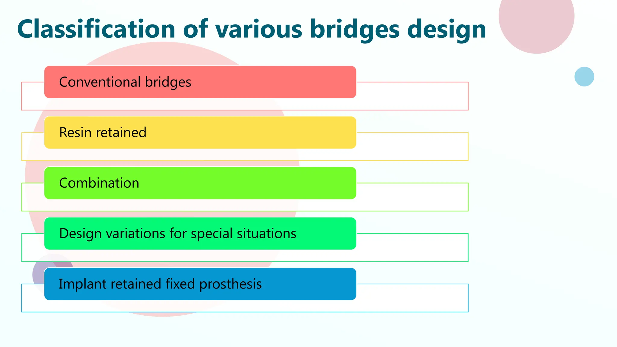
UNCONVENTIONAL
BRIDGES
DR. SATVIKA PRASAD
MDS
DEPARTMENT OF PROSTHODONTICS
CONTENTS
• Introduction
• Classification
• Conventional bridge design
• Resin retained bridges
• Combination bridges
• Design variations for special situations
• Implant retained fixed prosthesis
• Tooth implant supported fixed prosthesis
• Conclusion
• References
INTRODUCTION
In the realm of prosthodontics, the restoration of edentulous spaces has
traditionally been dominated by conventional fixed and removable prostheses.
However, advancements in dental materials and innovative techniques have paved
the way for unconventional bridges, offering unique solutions to complex clinical
scenarios. These unconventional bridges, provide versatile options that cater to
specific patient needs where traditional approaches may fall short.
By expanding the prosthodontist's toolkit, these innovative bridges enhance
esthetic outcomes, improve functionality, and increase patient satisfaction,
ultimately pushing the boundaries of restorative dentistry.
Fixed dental prosthesis :-
Any prosthesis that is fixed to a natural tooth or teeth, or to one or more dental
implants/ implant abutments and that which cannot be removed by the patient
-GPT 9
Classification of various bridges design
Conventional bridges
Resin retained
Combination
Design variations for special situations
Implant retained fixed prosthesis
Conventional bridge design
Based on the type of support provided at each ends of the pontic
1. Fixed- fixed
2. Cantilever bridge
3. Spring cantilever bridge
Fixed – fixed bridge
• Rigid connector on both ends of the pontic
• This design provides desirable strength and stability to the prosthesis
• Abutment teeth should be parallel to each other, so as to have single path of
insertion
1. Robust design provides
maximum strength and
retention
2. Abutment teeth are splinted
together ease of fabrication
3. Design is most practical for
larger bridges.
4. Helps to splint mobile
abutments
1. More tooth reduction is
required
2. Cannot be used in tilted
abutments
3. Require parallel preparation
4. Since the connectors are
rigid, unwanted stress and
lever forces are directly
transferred to the abutment
producing considerable
damage.
ADVANTAGES
DISADVANTAGES
Cantilever bridge
• It is used when support can be obtained from one side of the edentulous space.
• These have compromised support
• The abutment teeth should be strong enough to withstand additional torsional
forces.
• Support can be obtained from more than one tooth on the same side of the
edentulous space.
1. Very conservative design
when a single abutment is
involved.
2. When secondary abutments
are used, parallel preparation
can be easily obtained
because the abutments are
adjacent to one another
3. Easy to fabricate
4. Easy maintenance and
cleaning
1. Produces torquing forces
on the abutment
2. Cannot be used to
restore long span
edentulous space
3. More design errors can
affect the abutments in a
large scale
4. Construction must be
rigid to avoid distortion
ADVANTAGES
DISADVANTAGES
Spring cantilever bridge
• It is a tooth and tissue supported bridge.
• This is a special cantilever bridge exclusively designed
for maxillary incisors but these can support only a
single pontic.
• Support is obtained from posterior abutments (usually
a single molar or a pair of splinted premolars)
• This is attached to the end of a long metal arm
running high into the palate and then sweeping down
to a rigid connector on the palatal side of a single
retainer or pair of splinted retainers
• The arm is so long and thin so that it is springy, but not
so thin that it would deform permanently under
ADVANTAGES
1. Can be used for diastema
cases.
2. Metal crown retainers that
require minimal tooth
preparation, can be used in
posterior teeth to replace missing
incisors
DISADVANTAGES
1. The connector bar may
interfere with the speech and
mastication.
2. Deformation of the connector
bar may produce coronal
displacement of the pontic.
3. There may be food entrapment
under the connector bar, which
may lead to tissue hyperplasia.
Resin retained bridges
These are minimal preparation bridges for resin retention luted to tooth structure,
primarily enamel which has been etched to provide micromechanical retention for the resin
cement.
INDICATIONS
• Short edentulous span areas
• Patient unwilling or unsuitable
for surgical treatment
• Adolescents with single missing
tooth (traumatic or congenital)
• Needle phobic patients
• Post orthodontic fixed retention
• In periodontally compromised-
as splinting
CONTRAINDICATIONS
• Heavily restored abutments
• Small sized abutments- peg
laterals
• Extensive caries
• Parafunctional habits
• Deep bite
• Mal- aligned abutments
• Mobile abutments
• Long span edentulous area
• Allergy to base metal alloys
Resin bonded
retainers
Mechanism of
attachment of
retainer to the
abutment
Properties of the
bonding resin
Design of the
framework
Degree of coverage
Number of
abutments
Framework rigidity
Bonding technique
Little or no removal
of tooth structure
Madhok S, Madhok S. Evolutionary Changes in Bridges Designs. IOSR J. Dent. Med. Sci. 2014;13:50-6.
Objective – cover as much enamel as possible without compromising occlusion,
esthetics and periodontal health
Weakest Link – bond between the framework and resin
Mechanical retention, micromechanical
retention, macroscopic mechanical and
chemical retention
ROCHETTE BRIDGE (macro - mechanical retention)
• Developed in 1973 by Rochette
• He used the technique principally for periodontal
splinting mandibular anterior teeth and also used
pontic in his design
• Use of wing like retainers with funnel shaped
perforations through them to enhance resin
retention
Rochette AL. Attachment of a splint to enamel of lower anterior teeth. The Journal of prosthetic dentistry. 1973 Oct 1;30(4):418-23.
Can be made of
zirconia as well
The perforation technique presents following limitations:-
• Weakening of the metal retainer by the perforations.
• Exposure to wear of the composite resin at the perforations
• Limited adhesion of the metal provided by the perforations.
DISADVANTAGES
• Weakening of the metal retainer by
perforations
• Limited adhesion
• Wear of composite resin
• Thick lingual retainers
• Plaque accumulation
In 1980, Livaditis modified the rochette
bridge to be used for posterior teeth
Posterio
r
retainer
Occlusa
l rest
Lingual
segmen
t
Proxima
l
segmen
t
Livaditis GJ. Cast metal resin-bonded retainers for posterior teeth. Journal of the American Dental Association (1939). 1980 Dec 1;101(6):926-9.
• Prevents displacement of the
restoration in a gingival direction
during trial insertion and final
bonding.
• Assists in transferring the occlusal
forces to the abutment tooth
• Approx. 1mm in diameter and 0.5mm
deep.
• The framework should extend well beyond the
contact area toward the proximo-facial line
angle.
• This slight “wrap around” design will provide
considerable stability in a facio-loingual
direction.
• The proximal segment should provide an
adequate connector area for pontics without
impinging on the soft tissues.
• The margin of the framework is located
supra-gingivally
• When it is necessary to terminate the
framework near the gingiva, the margin
of the retainer must be well adapted
with a knife edge finish line
• The general objective is to obtain
maximum coverage for a greater bond.
OCCLUSAL REST
LINGUAL SEGMENT
PROXIMAL SEGMENT
Virginia bridge (medium mechanical retention)
• In 1983, Moon & Knap developed a roughened metal
surface by using salt crystals to create voids in self curing
acrylic resin patterns
• In 1985, Hudgins used the lost salt technique for the
fabrication of resin bonded metal retainers giving the
framework macroscopic mechanical means of retention
with the resin cement
• Roughened surface of the retainer itself provides for
retention
• Achieved by lost salt technique
• Air abrasion with aluminum oxide
Technique
Working cast with
lubricant
Specially sized salt
crystals (150-
250μm) are
sprinkled leaving
0.5mm border
Application of wax
pattern
Salt is dissolved
before investing to
give a rough
surface for resin tag
formation
Another method involves the use of a mesh pattern with
a design similar to woven screen wire
• Another example of void
containing framework is the
technique involving cast mesh
given by Shen in 1984
• Example of net-like wire mesh used
in cast mesh bridge is Kett- O-
Bond.
• This technique gives moderate to
good retention but the framework
is bulky.
ADVANTAGES
• Can be used with any alloy esp. gold alloys and those with a high
palladium content, which have no etchants.
• Elimination of the etching process. Therefore, reduced cost, time
and health hazards
• The grey discoloration commonly transmitted through the enamel
when cast etched retainers are used was not apparent with the
mesh system
Maryland bridges
• These are resin bonded bridge using electrolytic etching of
metal to retain the metal framework using micromechanical
retention
• Thompson & Livaditis in 1983 developed a technique of
electrolytic etching of Ni-Cr and Co-Cr alloy
Electrolytic etching
• The polished bridge is mounted on an electrode (the electrode to the lingual of the
retainers).
• Electrical continuity is assured by use of a conductive paint at the contact point,
and all areas not to be etched (and the electrode) are then masked with sticky wax.
• The electrode and bridge are mounted opposite a stainless steel electrode and
immersed in an appropriate acid.
• The bridge is made anodic and current passed at a given density for a prescribed
time.
• The etching acid, its concentration, the current density, and etching time must be
carefully determined for a given alloy in order to get maximum resin to alloy bond
strengths.
• Use of the wrong acid can result in electropolishing rather than etching
• The conditions for etching a commonly used Ni-Cr-Mo-Al-Be alloy are:
• 10% sulfuric acid at a current density of 300 milliamperes per square centimeter of
surface to be etched for a period of 3 minutes.
• The etched surface will be occluded with a black debris layer following etching and must
be cleaned in 18% hydrochloric acid in an ultrasonic bath for 15 minutes.
• The etched surface will then have a matt grey appearance and care should be exercised
to avoid contamination of the surface.
BONDING:-
• Upon seating the patient, the bridge is solvent rinsed with acetone or chloroform, the
abutment teeth are isolated and thoroughly cleaned with flour of pumice -- with
particular attention to the lingual and proximal surfaces -- and then rinsed. 37%
phosphoric acid is used for etching, for 90 seconds
• Following thorough rinsing and drying a bonding resin is applied to the etched
abutments and then to the etched surfaces of the bridge, & cured for 90 seconds. The
low film thickness composite is then immediately applied to the bridge and the bridge
seated before the bonding agent sets. The bridge is then held under pressure until the
composite sets.
ADVANTAGES
• Better retention: resin –
etched metal bond is
stronger than resin to
etched tooth
• Retainers are highly
polished and resists plaque
accumulation
DISADVANTAGES
• Etch is alloy specific
requiring special apparatus
• Only non- precious alloy
which can be etched is
used
• Precious alloys cannot be
etched. E.g.- Au, Ag, Pt, Pd
Two techniques of etching
Two step etching
Use a 3.5% solution of nitric acid with a current of
250mA/sq-cm followed by immersion in an 18%
hydrochloric acid solution in an ultrasonic cleaner
for 10 minutes
One step etching
Combined solution of sulfuric acid and hydrochloric
acids placed in an activated ultrasonic cleaner with
electric current passed for 95 seconds (McLaughling)
Chair side etching
The bridge is clipped to the anode of etching
unit and touched with an absorbent point
soaked in the etching solution and connected
to cathode
Reverse Maryland Bridges
Utilizing the Maryland bridge applied from the labial and buccal aspect
Bonding
• The intaglio surfaces were etched with 5% hydrofluoric acid for 20 seconds.
• After rinsing and drying, an MDP-containing ceramic primer was applied and then
dried.
• An MDP-containing dentin adhesive was then applied to the intaglio surfaces, air-
thinned, and followed with an application of a highly-filled, flowable resin
composite.
• Both restorations were then isolated from any light sources.
• The teeth were isolated, etched with 37% phosphoric acid, rinsed, and dried.
• An application of the same MDP-containing dentin adhesive was then applied to
all of the prepared tooth surfaces and air-thinned to remove the solvent.
• The adhesive layer was not light-cured at this time.
• Both of the bridges that were preloaded with flowable resin composite were then
inserted, and the excess cement was removed with cotton rolls and micro-
brushes.
• While holding the restorations in place, the facial and lingual surfaces of the
abutments were light-cured.
Gregg A. Helvey: Facially-Retained Maryland Bridges-An alternative approach to the resin-bonded, fixed partial; Inside Dentistry October 2018 Volume 14, Issue 10
Procera Maryland Bridge
• Further evolution of Livaditis’ initial concept.
• The one piece zirconia framework incorporates an
all ceramic pontic connecting two wings that are
bonded (or cemented) to the lingual surface of the
adjacent teeth.
• The preparation is limited to 0.5mm or less of the
enamel layer.
• The framework is precision milled from a solid
piece of zirconia.
• Zirconia cannot be acid-etched, so to increase the
bond strength a proprietary process for coating
them with porcelain, etching the porcelain, and
bonding the porcelain surface to the teeth with
composite
The Procera Maryland Bridge: A Case Report
The patient was an 18-year-old female who presented with an undersized right
lateral incisor and a congenitally missing left lateral incisor. However, consecutive
cephalometric radiographs indicated that she had not reached full physical
maturity and thus, was not yet a candidate for single implant placement. After a
review of her options, she elected to receive a Procera Maryland Bridge as an
interim solution.
Holt LR, Drake B. The procera Maryland bridge: A case report. Journal of Esthetic and
Restorative Dentistry. 2008 Jun;20(3):165-71.
Zirconium
framework on
die model
without
porcelain on
pontic.
Central and
lateral tooth
preparation
ADHESIVE BRIDGES
Chemically active adhesive cements were developed for direct bonding to metal
The preparation is treated
with a self curing enamel
and dentinal bonding agent
The internal surface of the
casting is sandblasted and
electroplated with tin to
produce a surface suitable
for bonding with a resin
cement
Adhesive systems
Chairside systems Laboratory systems
• Metabond – 1st
adhesive
resin system
• MMA polymer &
monomer
• Catalyst- tributyl borate
• Adhesive- 4-META
• Superbond
• Highest initial bond
strengths
• Weak bond with gold
alloys
• Bond shows hydrolytic
instability
• Silicoater classical
• Immediate layer
containing silica as this
provides sufficient
bonding of the resin via a
silane bonding agent
• Rocatec System
• A tribochemical silica
coating is sandblasted
onto the metal surface to
provide ultrafine
mechanical retention
Fiber reinforced composite resin
• Consists of a fiber reinforced substructure
• Translucent
• Veneered with composite material
• Increased flexural strength, fracture
resistance, tensile strength
Classification
Types
of
fibers
Glass
Polyethylene
Polypropylene
Carbon
Orientation
Unidirectional
Braided
Woven
Reinforcement
Non- impregnated
Pre- impregnated
and machine formed
Pre- impregnated
and woven
INDICATIONS-
• Esthetics
• The need to decrease wear
of the opposing dentition
• The use of conservative
abutment tooth
preparations
• The desire for a metal free,
non porcelain prosthesis
CONTRINDICATIONS-
• Inability to maintain good
fluid control
• Long span (two or more
pontics)
• Patients with parafunctional
habits
• Patients with unglazed
porcelain or RPD frameworks
that would oppose the
restoration
Anterior Fiber-reinforced Composite Resin Bridge: A
Case Report
A 16-year-old boy was referred to the Department of Pediatric Dentistry who has
lost maxillary right permanent central incisor. The removable acrylic splint
appliance had been repaired several times, mainly in the middle anterior region.
As implant procedure cannot be done until boy turned 18 as he had not reached
full physical maturity so he opted this procedure.
Chafaie A, Portier R. Anterior fiber-reinforced composite resin bridge: a case report.
Pediatric dentistry. 2004 Nov 1;26(6):530-4.
• Thin foil was closely adapted to the working cast
(Figure 2). The foil extended to the middle thirds of
each abutment and crossed the pontic area directly
under the incisal edge.
• The foil was flattened and used as a pattern, against
which the exact length of the ribbon needed was
measured.
One should avoid touching the ribbon until
after it is wetted with bonding resin via the
fingers, because
any contact can contaminate its reactive surface
layer
The reinforcement material
was impregnated with a
hydrophobic solvent-free
bonding resin
Following the impregnation
with
the bonding resin, the fiber
material became translucent
A thin layer of a microhybrid
restorative material was
placed on the lingual side of
the abutment teeth.
This composite acted as a
glue and held the ribbon
during itsadaptation
Using instruments, the
ribbon was pushed through
the uncured composite layer
until it
touched the surface of the
die material, like the foil
Once adapted, excess
composite was removed
before light curing
A second piece of the ribbon
was used in the pontic region
at this stage. It went to the
proximal lingual surface
angle of each abutment
The composite pontic was
built around the composite
laminate framework
The wings was acid-etched
for 1 minute and then
thoroughly rinsed and
completely air dried.
A porcelain primer was then
applied for 30 seconds and
air dried
Two layers of a universal 1-
bottle adhesive was then
applied, thoroughly air dried
for 15 seconds, and light
cured for 10 seconds
Teeth was acid etched and
adhesive was applied and
light cured for 10 seconds
Then the prosthesis was
cemented with dual cure
cement after etching the
tooth
Case report
• A 21 year patient reported to the department of prosthodontics, MM
College of Dental Sciences & Research, Mullana.
• She had a chief complaint of missing teeth in maxillary anterior region due
to trauma.
• She had sufficient bone height and width for implant placement and she
opted for it also.
• After implant placement, we had to provide her with the provisional
restoration, but she was reluctant to have removable prosthesis due to peer
pressure.
• So we splinted acrylic tooth with fiber splint and kept it out of occlusion in
all mandibular movements.
We can give provisional prosthesis also with this unconventional bridges
DR. SATVIKA PRASAD
DR. SATVIKA PRASAD
DR. SATVIKA PRASAD
DR. SATVIKA PRASAD
Combination bridges
1. COMPOUND BRIDGE
A combination of any two or more of the conventional bridges
design is referred to as compound bridge.
• The fixed-fixed & cantilever design
• The fixed-fixed & fixed movable design
• A bridge with a removable buccal flange that replaces lost
alveolar tissue
ADVANTAGES
• Simplifies the construction of the prosthesis
• Complex bridge to be broken down into several
parts
• Unfavorable angulation of abutment can be
corrected resulting in same line of insertion
• Precision retainers- permits the separation of
two or more components
Hybrid bridges
Fixed movable connectors are employed in case of
hybrid bridges
Resin bonded + conventional retainers = Hybrid
bridge
MAJOR RETAINER
So that debonding does not
require replacement of
conventional retainer
Hybrid means the combination of two
varieties of prostheses. On the one hand, it is
a fixed prosthesis, since the patient cannot
remove the prosthesis from the mouth; it is
fixed, and constructed of two or more
different materials. The goal was to give
patients an option that was not removable,
but that was removable by the clinician to
clean and tighten or replace screws
periodically.
Design variations for special situations
1. Andrew’s bridge
2. Telescopic prosthesis
3. Non – rigid connectors
Andrews bridge
• Dr. James Andrews introduced the fixed removable Andrews bridge
system.
• Improve or achieve comfort, hygiene, normal phonetics and
aesthetics
• Abutment tooth stabilization is combined with a removable partial
denture to resolve challenging aesthetic problems
Andrew’s
bridge
Fixed
retainers
Removable
pontic
Pontic assembly that is removed by the
patient for preventive maintenance
• These prefabricated units were made of precision machined stainless
steel rather than gold alloy
• Very high tensile and yield strengths were claimed for the material so that
the bar could be made thin and also occupy minimal vertical space
INDICATIONS-
• Excessive residual ridge defect
either due to trauma or surgical
ablation
• Cleft palate patients with
congenital or acquired defects
ADVANTAGES-
• Has all the advantages of both fixed and
removable i.e. better aesthetics, hygiene
along with better adaptability and
phonetics
• Comfortable and economical to patient
• No plate as in RPD
• No soft tissue impingement and the
surrounding structures
• System acts as stress breaker while
transmitting unwanted leverage forces
• Flexibility in placing denture teeth
DISADVANTAGES-
• Complex laboratory steps
TELESCOPIC PROSTHESIS
• Used in non- parallel abutments
• It enables the mesial and distal surfaces to be prepared
for single path of insertion
ADVANTAGES –
• Easy access for oral hygiene
• Better retention
• Can include teeth with questionable long term prognosis
Non – rigid connectors
INDICATIONS-
• Pier abutment
• Mal-aligned
abutment
• Mobile teeth
• Long span FPDs
Tenon – mortise connectors Cross pin and wing connectors
Split pontic connector
Loop connectors
Moulding MB, Holland GA, Sulik WD. An alternative orientation of nonrigid connectors in fixed partial dentures. The Journal of Prosthetic Dentistry. 1992 Aug 1;68(2):236-8.
Tenon mortise connector
KEY & KEYWAY
an interlock using a matrix and patrix between the
units of a fixed dental prosthesis. It may serve two
functions:
1) to hold the pontic in the proper relationship to the
edentulous ridge and the opposing teeth during
occlusal adjustment on the working cast (during
application of any veneering material) and
Keyway is fabricated
in the wax pattern
Casting of 1st
part i.e.
matrix is done
Auto polymerizing
acrylic resin is
inserted into the
keyway and then
attached to the 2nd
part i.e. patrix
Patrix is casted
separately
Banerjee S, Khongshei A, Gupta T, Banerjee A. Non-rigid connector: The wand to allay the stresses on abutment. Contemporary Clinical Dentistry. 2011 Oct 1;2(4):351-4.
Reverse key and keyway
If non rigid connector is placed on distal
side of the middle abutment, any mesial
movement seats the key into keyway
If connector is located on mesial side of
the middle abutment, mesial movement
of the teeth tends to unseat key
Split pontic
• This is an attachment that is placed entirely within the pontic
• It is particularly useful in tilted abutment cases
Casting of mesial half is done
Wax is poured into it
Casting of distal half
O'Connor RP, Caughman WF, Bemis C. Use of the split pontic nonrigid connector with the tilted molar abutment. The Journal of prosthetic dentistry. 1986
Aug 1;56(2):249-51.
• The cross pin and wing are the working elements of a two piece pontic system
that allows the two segments to be rigidly fixed after the retainers have been
cemented on their respective abutment preparations
• The design is used primarily in teeth with disparate long axes. The path of
insertion of each tooth preparation is made parallel to the long axis of that
tooth.
Specifications of wing:-
• Parallel to path of Insertion of mesial abutment
• Extend 3mm mesially
• 1mm faciolingually thickness
• 1mm short of occlusal surface
Cross pin & wing
Loop connector
• Loop connectors are required when an
existing diastema is to be maintained in a
planned fixed prosthesis.
• The connector consists of a loop on the
lingual aspect of the prosthesis that
connects adjacent retainers and/or
pontics.
• The loop may be cast from sprue wax or
Pt-Au-Pd alloy wire
• Meticulous design is important so that
plaque control will not be impeded
CASE REPORT
• A 23 year old patient visited to the Department of Prosthodontics, MM
college of Dental Sciences & Research, Mullana.
• He had a chief complaint of missing teeth in upper anterior region due
to trauma.
• Both lateral incisors were congenitally missing.
• Due to loss of bone, implants cannot be placed.
• He was presented with various options in FPD, but he opted for loop
connectors, as earlier patient had diastema so he wanted to maintain it.
DR. SATVIKA PRASAD
DR. SATVIKA PRASAD
DR. SATVIKA PRASAD
DR. SATVIKA PRASAD
DR. SATVIKA PRASAD
Implant retained fixed prosthesis
Porcelain metal
restoration
• Ceramic layer
bonded to a cast
metal framework
• Increased bulk of
metal used in the
substructure to keep
porcelain to its ideal
2mm thickness
Prosthetic options in fixed full arch restorations
Hybrid prosthesis
• Metal
framework +
acrylic resin +
artificial denture
teeth
• The impact force
during dynamic
occlusal loading
also is reduced
Tooth implant supported fixed prosthesis
Anatomical limitations of space for implants or failure of an implant
to osseointegrate may create a situation in which it would be
desirable to connect the implants to teeth.
It was 1st
introduced by Ericcson et al.
• Whether or not it is acceptable to connect an implant to a
tooth, or teeth, in a restoration is one of the most
misunderstood areas of implant dentistry. The reason so
much confusion exists is simple: there isn’t one correct
answer.
• To understand why, we must look at the mechanics of
connecting an implant and a tooth; recognizing that the
implant is essentially ankylosed, with effectively no mobility,
the tooth has a PDL and may have minimal to significant
levels of mobility.
• Under occlusal loading, the implant, being less mobile, will
always be at greater risk of receiving increased load. The
tooth will never be at risk of being over-loaded, as it is more
mobile and would move under the load compared to the
implant.
• If connecting a single implant to single tooth which has no
mobility, the risk of significantly increasing the load on the
implant is very low, even in the case of an FPD where there
may be pontics between the implant and tooth.
He was referred to the dentist in 1986 after fracturing porcelain and solder joints on his
fourth reconstruction in only 10 years, he has a history of severe bruxism. After removing
the old reconstruction he was left with a maxillary right canine that had endo and a post
core, and on the left side a lateral, canine and both premolars. All five remaining teeth had
a Grade 2 mobility.
in the mid 1980s it was rarely considered sacrificing a natural tooth to place an implant. So
the surgeon placed two implants, one in the right lateral position, and one in the right
second premolar position. Then placed gold copings on all the natural teeth. In addition a
one-piece superstructure was temporarily cemented over the teeth and implants.
The problem is that the one-piece restoration is effectively cantilevered off of the two
implants due to the Grade 2 mobility of the natural teeth. It took three years, but ultimately
he lost the integration of the second premolar implant and it came out when the dentist
went to remove the temporarily cemented superstructure.
Connecting Teeth and Implants: Yes, No, Maybe? By Frank Spear on May 7, 2018
second premolar, where the implants had been, into pontics. It is interesting when all the
teeth are equally mobile, and you use a one-piece restoration, to see how well they do. He
went seven years before finally the right canine root fractured. We then removed all the
teeth and went to a completely implant supported restoration using eight implants to
support his high levels of muscle activity.
Having focused on the risk for the implant when connecting them to a natural tooth, there
is one concern for the natural teeth, intrusion, the tooth moving apically out from under
the prosthesis.
This is an issue that has occurred for decades, not just with teeth and implants.
In the old days of periodontal prosthesis, where each tooth received a gold coping that was
permanently cemented with a full arch restoration temporarily cemented over the top, it
was not unusual to see an isolated tooth or teeth intrude out from under the prosthesis,
sometimes by as much as 1 to 1.5mm
connection so that the implant restoration didn’t rotate and come loose. In addition, because of how weak
the screw was connecting the restoration to the abutment, it was necessary to place the female portion of
the non-rigid attachment on the natural tooth, and the male on the implant. This allowed for removal and
retrieval of broken or loose screws after the restorations were placed. But it also created a situation where
the natural tooth could intrude relative to the implant, and on occasion they did.
• The classic coping and one-piece superstructure design used in the 1980s and 1990s is also susceptible to
natural tooth intrusion if the temporary cement washes out between a coping and the superstructure, it
now allowed the natural tooth to move independently of the restoration, and intrusion was a possibility.
Several theories have been postulated as to why intrusion occurs.
• With the risks of overloading of the implant, and intrusion of the teeth, it would seem reasonable to ask
WHY you would want to connect an implant and a tooth, but there are times where it may be necessary, and
sometimes even desirable.
• The most common reason would be because you HAVE to, an example might be a patient missing a lower
first and second molar. A surgeon places two implants, one for each missing molar, but what if the first
molar implant doesn’t integrate? A new implant is placed for the first molar, but it also doesn’t integrate. The
patient says NO MORE, they want the restorations, your only choice is to connect the second molar implant
to the second premolar and do a 3-unit FPD.
Connecting Teeth and Implants: Yes, No, Maybe? By Frank Spear on May 7, 2018
CONCLUSION
• A common axiom in conventional prosthodontics for partial edentulism is a fixed
partial denture. Fewer the natural teeth missing better the indication for fixed
partial denture.
• Unfortunately every case is different in relation to anatomical variations, patient's
desires and medical condition, therefore subtle modifications in designing are
required to suit a given particular case.
• Over the period of time many types of bridges have come up ranging from the
traditional to resin retained to the implant retained bridges. With the treatment
options available today the primary goal of a prosthodontist should be
"meticulous replacement with maximum preservation."
References
1. Misch, C.E., 2004. Dental implant prosthetics-E-book. Elsevier Health Sciences.
2. Shillingburg HT, Hobo S, Whitsett LD, Jacobi R, Brackett SE. Fundamentals of fixed
prosthodontics. Hanover Park, IL: Quintessence Publishing Company; 2012.
3. Rosenstiel SF, Land MF, editors. Contemporary Fixed Prosthodontics-E-Book:
Contemporary Fixed Prosthodontics-E-Book. Elsevier Health Sciences; 2015 Jul 28.
4. Madhok S, Madhok S. Evolutionary Changes in Bridges Designs. IOSR J. Dent. Med. Sci.
2014;13:50-6.
5. Rochette AL. Attachment of a splint to enamel of lower anterior teeth. The Journal of
prosthetic dentistry. 1973 Oct 1;30(4):418-23.
6. Livaditis GJ. Cast metal resin-bonded retainers for posterior teeth. Journal of the
American Dental Association (1939). 1980 Dec 1;101(6):926-9.
7. Taleghani M, Leinfelder KF, Taleghani AM. An alternative to cast etched retainers. The
Journal of Prosthetic Dentistry. 1987 Oct 1;58(4):424-8.
8. Livaditis GJ, Thompson VP. Etched castings: an improved retentive mechanism for
resin-bonded retainers. The Journal of prosthetic dentistry. 1982 Jan 1;47(1):52-8.
9. Badwaik PV, Pakhan AJ. Non-rigid connectors in fixed prosthodontics: Current concepts
with a case report. The Journal of Indian Prosthodontic Society. 2005 Apr 1;5(2):99-102.
10. Miller TE. Reverse Maryland bridges: clinical applications. Journal of Esthetic and Restorative
Dentistry. 1989 Sep;1(5):155-63.
11. Holt LR, Drake B. The procera Maryland bridge: A case report. Journal of Esthetic and
Restorative Dentistry. 2008 Jun;20(3):165-71.
12. Langer Y, Langer A. Tooth-supported telescopic prostheses in compromised dentitions: A
clinical report. Journal of prosthetic dentistry. 2000 Aug 1;84(2):129-32.
13. Moulding MB, Holland GA, Sulik WD. An alternative orientation of nonrigid connectors in fixed
partial dentures. The Journal of Prosthetic Dentistry. 1992 Aug 1;68(2):236-8.
14. Banerjee S, Khongshei A, Gupta T, Banerjee A. Non-rigid connector: The wand to allay the
stresses on abutment. Contemporary Clinical Dentistry. 2011 Oct 1;2(4):351-4.
15. Gopi A, Sahoo NK. Andrews Bridge: A fixed removable prosthesis, J Pierre Fauchard Acad (India
Sect). (2016)
16. O'Connor RP, Caughman WF, Bemis C. Use of the split pontic nonrigid connector with the tilted
molar abutment. The Journal of prosthetic dentistry. 1986 Aug 1;56(2):249-51.
17. Connecting Teeth and Implants: Yes, No, Maybe? By Frank Spear on May 7, 2018
18. Chafaie A, Portier R. Anterior fiber-reinforced composite resin bridge: a case report. Pediatric
dentistry. 2004 Nov 1;26(6):530-4.
19. Gregg A. Helvey: Facially-Retained Maryland Bridges-An alternative approach to the resin-
bonded, fixed partial; Inside Dentistry October 2018 Volume 14, Issue 10
20. Academy of Denture Prosthetics. Nomenclature Committee. Glossary of prosthodontic terms.
Journal of Prosthetic Dentistry, CV Mosby; 1987.

UNCONVENTIONAL BRIDGES: INNOVATIVE APPROACH IN MODERN PROSTHODONTICS.pptx

  • 1.
  • 2.
    CONTENTS • Introduction • Classification •Conventional bridge design • Resin retained bridges • Combination bridges • Design variations for special situations • Implant retained fixed prosthesis • Tooth implant supported fixed prosthesis • Conclusion • References
  • 3.
    INTRODUCTION In the realmof prosthodontics, the restoration of edentulous spaces has traditionally been dominated by conventional fixed and removable prostheses. However, advancements in dental materials and innovative techniques have paved the way for unconventional bridges, offering unique solutions to complex clinical scenarios. These unconventional bridges, provide versatile options that cater to specific patient needs where traditional approaches may fall short. By expanding the prosthodontist's toolkit, these innovative bridges enhance esthetic outcomes, improve functionality, and increase patient satisfaction, ultimately pushing the boundaries of restorative dentistry.
  • 4.
    Fixed dental prosthesis:- Any prosthesis that is fixed to a natural tooth or teeth, or to one or more dental implants/ implant abutments and that which cannot be removed by the patient -GPT 9
  • 5.
    Classification of variousbridges design Conventional bridges Resin retained Combination Design variations for special situations Implant retained fixed prosthesis
  • 6.
    Conventional bridge design Basedon the type of support provided at each ends of the pontic 1. Fixed- fixed 2. Cantilever bridge 3. Spring cantilever bridge
  • 7.
    Fixed – fixedbridge • Rigid connector on both ends of the pontic • This design provides desirable strength and stability to the prosthesis • Abutment teeth should be parallel to each other, so as to have single path of insertion
  • 8.
    1. Robust designprovides maximum strength and retention 2. Abutment teeth are splinted together ease of fabrication 3. Design is most practical for larger bridges. 4. Helps to splint mobile abutments 1. More tooth reduction is required 2. Cannot be used in tilted abutments 3. Require parallel preparation 4. Since the connectors are rigid, unwanted stress and lever forces are directly transferred to the abutment producing considerable damage. ADVANTAGES DISADVANTAGES
  • 9.
    Cantilever bridge • Itis used when support can be obtained from one side of the edentulous space. • These have compromised support • The abutment teeth should be strong enough to withstand additional torsional forces. • Support can be obtained from more than one tooth on the same side of the edentulous space.
  • 10.
    1. Very conservativedesign when a single abutment is involved. 2. When secondary abutments are used, parallel preparation can be easily obtained because the abutments are adjacent to one another 3. Easy to fabricate 4. Easy maintenance and cleaning 1. Produces torquing forces on the abutment 2. Cannot be used to restore long span edentulous space 3. More design errors can affect the abutments in a large scale 4. Construction must be rigid to avoid distortion ADVANTAGES DISADVANTAGES
  • 11.
    Spring cantilever bridge •It is a tooth and tissue supported bridge. • This is a special cantilever bridge exclusively designed for maxillary incisors but these can support only a single pontic. • Support is obtained from posterior abutments (usually a single molar or a pair of splinted premolars) • This is attached to the end of a long metal arm running high into the palate and then sweeping down to a rigid connector on the palatal side of a single retainer or pair of splinted retainers • The arm is so long and thin so that it is springy, but not so thin that it would deform permanently under
  • 12.
    ADVANTAGES 1. Can beused for diastema cases. 2. Metal crown retainers that require minimal tooth preparation, can be used in posterior teeth to replace missing incisors DISADVANTAGES 1. The connector bar may interfere with the speech and mastication. 2. Deformation of the connector bar may produce coronal displacement of the pontic. 3. There may be food entrapment under the connector bar, which may lead to tissue hyperplasia.
  • 13.
    Resin retained bridges Theseare minimal preparation bridges for resin retention luted to tooth structure, primarily enamel which has been etched to provide micromechanical retention for the resin cement. INDICATIONS • Short edentulous span areas • Patient unwilling or unsuitable for surgical treatment • Adolescents with single missing tooth (traumatic or congenital) • Needle phobic patients • Post orthodontic fixed retention • In periodontally compromised- as splinting CONTRAINDICATIONS • Heavily restored abutments • Small sized abutments- peg laterals • Extensive caries • Parafunctional habits • Deep bite • Mal- aligned abutments • Mobile abutments • Long span edentulous area • Allergy to base metal alloys
  • 14.
    Resin bonded retainers Mechanism of attachmentof retainer to the abutment Properties of the bonding resin Design of the framework Degree of coverage Number of abutments Framework rigidity Bonding technique Little or no removal of tooth structure Madhok S, Madhok S. Evolutionary Changes in Bridges Designs. IOSR J. Dent. Med. Sci. 2014;13:50-6.
  • 15.
    Objective – coveras much enamel as possible without compromising occlusion, esthetics and periodontal health Weakest Link – bond between the framework and resin Mechanical retention, micromechanical retention, macroscopic mechanical and chemical retention
  • 16.
    ROCHETTE BRIDGE (macro- mechanical retention) • Developed in 1973 by Rochette • He used the technique principally for periodontal splinting mandibular anterior teeth and also used pontic in his design • Use of wing like retainers with funnel shaped perforations through them to enhance resin retention Rochette AL. Attachment of a splint to enamel of lower anterior teeth. The Journal of prosthetic dentistry. 1973 Oct 1;30(4):418-23. Can be made of zirconia as well
  • 17.
    The perforation techniquepresents following limitations:- • Weakening of the metal retainer by the perforations. • Exposure to wear of the composite resin at the perforations • Limited adhesion of the metal provided by the perforations. DISADVANTAGES • Weakening of the metal retainer by perforations • Limited adhesion • Wear of composite resin • Thick lingual retainers • Plaque accumulation
  • 18.
    In 1980, Livaditismodified the rochette bridge to be used for posterior teeth Posterio r retainer Occlusa l rest Lingual segmen t Proxima l segmen t Livaditis GJ. Cast metal resin-bonded retainers for posterior teeth. Journal of the American Dental Association (1939). 1980 Dec 1;101(6):926-9.
  • 19.
    • Prevents displacementof the restoration in a gingival direction during trial insertion and final bonding. • Assists in transferring the occlusal forces to the abutment tooth • Approx. 1mm in diameter and 0.5mm deep. • The framework should extend well beyond the contact area toward the proximo-facial line angle. • This slight “wrap around” design will provide considerable stability in a facio-loingual direction. • The proximal segment should provide an adequate connector area for pontics without impinging on the soft tissues. • The margin of the framework is located supra-gingivally • When it is necessary to terminate the framework near the gingiva, the margin of the retainer must be well adapted with a knife edge finish line • The general objective is to obtain maximum coverage for a greater bond. OCCLUSAL REST LINGUAL SEGMENT PROXIMAL SEGMENT
  • 20.
    Virginia bridge (mediummechanical retention) • In 1983, Moon & Knap developed a roughened metal surface by using salt crystals to create voids in self curing acrylic resin patterns • In 1985, Hudgins used the lost salt technique for the fabrication of resin bonded metal retainers giving the framework macroscopic mechanical means of retention with the resin cement • Roughened surface of the retainer itself provides for retention • Achieved by lost salt technique • Air abrasion with aluminum oxide
  • 21.
    Technique Working cast with lubricant Speciallysized salt crystals (150- 250μm) are sprinkled leaving 0.5mm border Application of wax pattern Salt is dissolved before investing to give a rough surface for resin tag formation
  • 22.
    Another method involvesthe use of a mesh pattern with a design similar to woven screen wire • Another example of void containing framework is the technique involving cast mesh given by Shen in 1984 • Example of net-like wire mesh used in cast mesh bridge is Kett- O- Bond. • This technique gives moderate to good retention but the framework is bulky.
  • 23.
    ADVANTAGES • Can beused with any alloy esp. gold alloys and those with a high palladium content, which have no etchants. • Elimination of the etching process. Therefore, reduced cost, time and health hazards • The grey discoloration commonly transmitted through the enamel when cast etched retainers are used was not apparent with the mesh system
  • 24.
    Maryland bridges • Theseare resin bonded bridge using electrolytic etching of metal to retain the metal framework using micromechanical retention • Thompson & Livaditis in 1983 developed a technique of electrolytic etching of Ni-Cr and Co-Cr alloy
  • 25.
    Electrolytic etching • Thepolished bridge is mounted on an electrode (the electrode to the lingual of the retainers). • Electrical continuity is assured by use of a conductive paint at the contact point, and all areas not to be etched (and the electrode) are then masked with sticky wax. • The electrode and bridge are mounted opposite a stainless steel electrode and immersed in an appropriate acid. • The bridge is made anodic and current passed at a given density for a prescribed time. • The etching acid, its concentration, the current density, and etching time must be carefully determined for a given alloy in order to get maximum resin to alloy bond strengths. • Use of the wrong acid can result in electropolishing rather than etching
  • 26.
    • The conditionsfor etching a commonly used Ni-Cr-Mo-Al-Be alloy are: • 10% sulfuric acid at a current density of 300 milliamperes per square centimeter of surface to be etched for a period of 3 minutes. • The etched surface will be occluded with a black debris layer following etching and must be cleaned in 18% hydrochloric acid in an ultrasonic bath for 15 minutes. • The etched surface will then have a matt grey appearance and care should be exercised to avoid contamination of the surface. BONDING:- • Upon seating the patient, the bridge is solvent rinsed with acetone or chloroform, the abutment teeth are isolated and thoroughly cleaned with flour of pumice -- with particular attention to the lingual and proximal surfaces -- and then rinsed. 37% phosphoric acid is used for etching, for 90 seconds • Following thorough rinsing and drying a bonding resin is applied to the etched abutments and then to the etched surfaces of the bridge, & cured for 90 seconds. The low film thickness composite is then immediately applied to the bridge and the bridge seated before the bonding agent sets. The bridge is then held under pressure until the composite sets.
  • 27.
    ADVANTAGES • Better retention:resin – etched metal bond is stronger than resin to etched tooth • Retainers are highly polished and resists plaque accumulation DISADVANTAGES • Etch is alloy specific requiring special apparatus • Only non- precious alloy which can be etched is used • Precious alloys cannot be etched. E.g.- Au, Ag, Pt, Pd
  • 28.
    Two techniques ofetching Two step etching Use a 3.5% solution of nitric acid with a current of 250mA/sq-cm followed by immersion in an 18% hydrochloric acid solution in an ultrasonic cleaner for 10 minutes One step etching Combined solution of sulfuric acid and hydrochloric acids placed in an activated ultrasonic cleaner with electric current passed for 95 seconds (McLaughling)
  • 29.
    Chair side etching Thebridge is clipped to the anode of etching unit and touched with an absorbent point soaked in the etching solution and connected to cathode
  • 31.
    Reverse Maryland Bridges Utilizingthe Maryland bridge applied from the labial and buccal aspect
  • 32.
    Bonding • The intagliosurfaces were etched with 5% hydrofluoric acid for 20 seconds. • After rinsing and drying, an MDP-containing ceramic primer was applied and then dried. • An MDP-containing dentin adhesive was then applied to the intaglio surfaces, air- thinned, and followed with an application of a highly-filled, flowable resin composite. • Both restorations were then isolated from any light sources. • The teeth were isolated, etched with 37% phosphoric acid, rinsed, and dried. • An application of the same MDP-containing dentin adhesive was then applied to all of the prepared tooth surfaces and air-thinned to remove the solvent. • The adhesive layer was not light-cured at this time. • Both of the bridges that were preloaded with flowable resin composite were then inserted, and the excess cement was removed with cotton rolls and micro- brushes. • While holding the restorations in place, the facial and lingual surfaces of the abutments were light-cured. Gregg A. Helvey: Facially-Retained Maryland Bridges-An alternative approach to the resin-bonded, fixed partial; Inside Dentistry October 2018 Volume 14, Issue 10
  • 33.
    Procera Maryland Bridge •Further evolution of Livaditis’ initial concept. • The one piece zirconia framework incorporates an all ceramic pontic connecting two wings that are bonded (or cemented) to the lingual surface of the adjacent teeth. • The preparation is limited to 0.5mm or less of the enamel layer. • The framework is precision milled from a solid piece of zirconia. • Zirconia cannot be acid-etched, so to increase the bond strength a proprietary process for coating them with porcelain, etching the porcelain, and bonding the porcelain surface to the teeth with composite
  • 34.
    The Procera MarylandBridge: A Case Report The patient was an 18-year-old female who presented with an undersized right lateral incisor and a congenitally missing left lateral incisor. However, consecutive cephalometric radiographs indicated that she had not reached full physical maturity and thus, was not yet a candidate for single implant placement. After a review of her options, she elected to receive a Procera Maryland Bridge as an interim solution. Holt LR, Drake B. The procera Maryland bridge: A case report. Journal of Esthetic and Restorative Dentistry. 2008 Jun;20(3):165-71.
  • 35.
    Zirconium framework on die model without porcelainon pontic. Central and lateral tooth preparation
  • 36.
    ADHESIVE BRIDGES Chemically activeadhesive cements were developed for direct bonding to metal The preparation is treated with a self curing enamel and dentinal bonding agent The internal surface of the casting is sandblasted and electroplated with tin to produce a surface suitable for bonding with a resin cement
  • 37.
    Adhesive systems Chairside systemsLaboratory systems • Metabond – 1st adhesive resin system • MMA polymer & monomer • Catalyst- tributyl borate • Adhesive- 4-META • Superbond • Highest initial bond strengths • Weak bond with gold alloys • Bond shows hydrolytic instability • Silicoater classical • Immediate layer containing silica as this provides sufficient bonding of the resin via a silane bonding agent • Rocatec System • A tribochemical silica coating is sandblasted onto the metal surface to provide ultrafine mechanical retention
  • 38.
    Fiber reinforced compositeresin • Consists of a fiber reinforced substructure • Translucent • Veneered with composite material • Increased flexural strength, fracture resistance, tensile strength
  • 39.
  • 40.
    INDICATIONS- • Esthetics • Theneed to decrease wear of the opposing dentition • The use of conservative abutment tooth preparations • The desire for a metal free, non porcelain prosthesis CONTRINDICATIONS- • Inability to maintain good fluid control • Long span (two or more pontics) • Patients with parafunctional habits • Patients with unglazed porcelain or RPD frameworks that would oppose the restoration
  • 41.
    Anterior Fiber-reinforced CompositeResin Bridge: A Case Report A 16-year-old boy was referred to the Department of Pediatric Dentistry who has lost maxillary right permanent central incisor. The removable acrylic splint appliance had been repaired several times, mainly in the middle anterior region. As implant procedure cannot be done until boy turned 18 as he had not reached full physical maturity so he opted this procedure. Chafaie A, Portier R. Anterior fiber-reinforced composite resin bridge: a case report. Pediatric dentistry. 2004 Nov 1;26(6):530-4.
  • 42.
    • Thin foilwas closely adapted to the working cast (Figure 2). The foil extended to the middle thirds of each abutment and crossed the pontic area directly under the incisal edge. • The foil was flattened and used as a pattern, against which the exact length of the ribbon needed was measured. One should avoid touching the ribbon until after it is wetted with bonding resin via the fingers, because any contact can contaminate its reactive surface layer
  • 43.
    The reinforcement material wasimpregnated with a hydrophobic solvent-free bonding resin Following the impregnation with the bonding resin, the fiber material became translucent A thin layer of a microhybrid restorative material was placed on the lingual side of the abutment teeth. This composite acted as a glue and held the ribbon during itsadaptation Using instruments, the ribbon was pushed through the uncured composite layer until it touched the surface of the die material, like the foil Once adapted, excess composite was removed before light curing A second piece of the ribbon was used in the pontic region at this stage. It went to the proximal lingual surface angle of each abutment The composite pontic was built around the composite laminate framework The wings was acid-etched for 1 minute and then thoroughly rinsed and completely air dried. A porcelain primer was then applied for 30 seconds and air dried Two layers of a universal 1- bottle adhesive was then applied, thoroughly air dried for 15 seconds, and light cured for 10 seconds Teeth was acid etched and adhesive was applied and light cured for 10 seconds Then the prosthesis was cemented with dual cure cement after etching the tooth
  • 44.
    Case report • A21 year patient reported to the department of prosthodontics, MM College of Dental Sciences & Research, Mullana. • She had a chief complaint of missing teeth in maxillary anterior region due to trauma. • She had sufficient bone height and width for implant placement and she opted for it also. • After implant placement, we had to provide her with the provisional restoration, but she was reluctant to have removable prosthesis due to peer pressure. • So we splinted acrylic tooth with fiber splint and kept it out of occlusion in all mandibular movements. We can give provisional prosthesis also with this unconventional bridges
  • 45.
    DR. SATVIKA PRASAD DR.SATVIKA PRASAD DR. SATVIKA PRASAD DR. SATVIKA PRASAD
  • 46.
    Combination bridges 1. COMPOUNDBRIDGE A combination of any two or more of the conventional bridges design is referred to as compound bridge. • The fixed-fixed & cantilever design • The fixed-fixed & fixed movable design • A bridge with a removable buccal flange that replaces lost alveolar tissue ADVANTAGES • Simplifies the construction of the prosthesis • Complex bridge to be broken down into several parts • Unfavorable angulation of abutment can be corrected resulting in same line of insertion • Precision retainers- permits the separation of two or more components
  • 47.
    Hybrid bridges Fixed movableconnectors are employed in case of hybrid bridges Resin bonded + conventional retainers = Hybrid bridge MAJOR RETAINER So that debonding does not require replacement of conventional retainer Hybrid means the combination of two varieties of prostheses. On the one hand, it is a fixed prosthesis, since the patient cannot remove the prosthesis from the mouth; it is fixed, and constructed of two or more different materials. The goal was to give patients an option that was not removable, but that was removable by the clinician to clean and tighten or replace screws periodically.
  • 48.
    Design variations forspecial situations 1. Andrew’s bridge 2. Telescopic prosthesis 3. Non – rigid connectors
  • 49.
    Andrews bridge • Dr.James Andrews introduced the fixed removable Andrews bridge system. • Improve or achieve comfort, hygiene, normal phonetics and aesthetics • Abutment tooth stabilization is combined with a removable partial denture to resolve challenging aesthetic problems Andrew’s bridge Fixed retainers Removable pontic Pontic assembly that is removed by the patient for preventive maintenance
  • 50.
    • These prefabricatedunits were made of precision machined stainless steel rather than gold alloy • Very high tensile and yield strengths were claimed for the material so that the bar could be made thin and also occupy minimal vertical space
  • 51.
    INDICATIONS- • Excessive residualridge defect either due to trauma or surgical ablation • Cleft palate patients with congenital or acquired defects ADVANTAGES- • Has all the advantages of both fixed and removable i.e. better aesthetics, hygiene along with better adaptability and phonetics • Comfortable and economical to patient • No plate as in RPD • No soft tissue impingement and the surrounding structures • System acts as stress breaker while transmitting unwanted leverage forces • Flexibility in placing denture teeth DISADVANTAGES- • Complex laboratory steps
  • 52.
    TELESCOPIC PROSTHESIS • Usedin non- parallel abutments • It enables the mesial and distal surfaces to be prepared for single path of insertion ADVANTAGES – • Easy access for oral hygiene • Better retention • Can include teeth with questionable long term prognosis
  • 53.
    Non – rigidconnectors INDICATIONS- • Pier abutment • Mal-aligned abutment • Mobile teeth • Long span FPDs
  • 54.
    Tenon – mortiseconnectors Cross pin and wing connectors Split pontic connector Loop connectors Moulding MB, Holland GA, Sulik WD. An alternative orientation of nonrigid connectors in fixed partial dentures. The Journal of Prosthetic Dentistry. 1992 Aug 1;68(2):236-8.
  • 55.
    Tenon mortise connector KEY& KEYWAY an interlock using a matrix and patrix between the units of a fixed dental prosthesis. It may serve two functions: 1) to hold the pontic in the proper relationship to the edentulous ridge and the opposing teeth during occlusal adjustment on the working cast (during application of any veneering material) and
  • 56.
    Keyway is fabricated inthe wax pattern Casting of 1st part i.e. matrix is done Auto polymerizing acrylic resin is inserted into the keyway and then attached to the 2nd part i.e. patrix Patrix is casted separately Banerjee S, Khongshei A, Gupta T, Banerjee A. Non-rigid connector: The wand to allay the stresses on abutment. Contemporary Clinical Dentistry. 2011 Oct 1;2(4):351-4.
  • 57.
  • 58.
    If non rigidconnector is placed on distal side of the middle abutment, any mesial movement seats the key into keyway If connector is located on mesial side of the middle abutment, mesial movement of the teeth tends to unseat key
  • 59.
    Split pontic • Thisis an attachment that is placed entirely within the pontic • It is particularly useful in tilted abutment cases Casting of mesial half is done Wax is poured into it Casting of distal half
  • 60.
    O'Connor RP, CaughmanWF, Bemis C. Use of the split pontic nonrigid connector with the tilted molar abutment. The Journal of prosthetic dentistry. 1986 Aug 1;56(2):249-51.
  • 61.
    • The crosspin and wing are the working elements of a two piece pontic system that allows the two segments to be rigidly fixed after the retainers have been cemented on their respective abutment preparations • The design is used primarily in teeth with disparate long axes. The path of insertion of each tooth preparation is made parallel to the long axis of that tooth. Specifications of wing:- • Parallel to path of Insertion of mesial abutment • Extend 3mm mesially • 1mm faciolingually thickness • 1mm short of occlusal surface Cross pin & wing
  • 62.
    Loop connector • Loopconnectors are required when an existing diastema is to be maintained in a planned fixed prosthesis. • The connector consists of a loop on the lingual aspect of the prosthesis that connects adjacent retainers and/or pontics. • The loop may be cast from sprue wax or Pt-Au-Pd alloy wire • Meticulous design is important so that plaque control will not be impeded
  • 63.
    CASE REPORT • A23 year old patient visited to the Department of Prosthodontics, MM college of Dental Sciences & Research, Mullana. • He had a chief complaint of missing teeth in upper anterior region due to trauma. • Both lateral incisors were congenitally missing. • Due to loss of bone, implants cannot be placed. • He was presented with various options in FPD, but he opted for loop connectors, as earlier patient had diastema so he wanted to maintain it.
  • 64.
    DR. SATVIKA PRASAD DR.SATVIKA PRASAD DR. SATVIKA PRASAD DR. SATVIKA PRASAD DR. SATVIKA PRASAD
  • 66.
    Implant retained fixedprosthesis Porcelain metal restoration • Ceramic layer bonded to a cast metal framework • Increased bulk of metal used in the substructure to keep porcelain to its ideal 2mm thickness Prosthetic options in fixed full arch restorations Hybrid prosthesis • Metal framework + acrylic resin + artificial denture teeth • The impact force during dynamic occlusal loading also is reduced
  • 67.
    Tooth implant supportedfixed prosthesis Anatomical limitations of space for implants or failure of an implant to osseointegrate may create a situation in which it would be desirable to connect the implants to teeth. It was 1st introduced by Ericcson et al.
  • 68.
    • Whether ornot it is acceptable to connect an implant to a tooth, or teeth, in a restoration is one of the most misunderstood areas of implant dentistry. The reason so much confusion exists is simple: there isn’t one correct answer. • To understand why, we must look at the mechanics of connecting an implant and a tooth; recognizing that the implant is essentially ankylosed, with effectively no mobility, the tooth has a PDL and may have minimal to significant levels of mobility. • Under occlusal loading, the implant, being less mobile, will always be at greater risk of receiving increased load. The tooth will never be at risk of being over-loaded, as it is more mobile and would move under the load compared to the implant. • If connecting a single implant to single tooth which has no mobility, the risk of significantly increasing the load on the implant is very low, even in the case of an FPD where there may be pontics between the implant and tooth.
  • 69.
    He was referredto the dentist in 1986 after fracturing porcelain and solder joints on his fourth reconstruction in only 10 years, he has a history of severe bruxism. After removing the old reconstruction he was left with a maxillary right canine that had endo and a post core, and on the left side a lateral, canine and both premolars. All five remaining teeth had a Grade 2 mobility. in the mid 1980s it was rarely considered sacrificing a natural tooth to place an implant. So the surgeon placed two implants, one in the right lateral position, and one in the right second premolar position. Then placed gold copings on all the natural teeth. In addition a one-piece superstructure was temporarily cemented over the teeth and implants. The problem is that the one-piece restoration is effectively cantilevered off of the two implants due to the Grade 2 mobility of the natural teeth. It took three years, but ultimately he lost the integration of the second premolar implant and it came out when the dentist went to remove the temporarily cemented superstructure. Connecting Teeth and Implants: Yes, No, Maybe? By Frank Spear on May 7, 2018
  • 70.
    second premolar, wherethe implants had been, into pontics. It is interesting when all the teeth are equally mobile, and you use a one-piece restoration, to see how well they do. He went seven years before finally the right canine root fractured. We then removed all the teeth and went to a completely implant supported restoration using eight implants to support his high levels of muscle activity. Having focused on the risk for the implant when connecting them to a natural tooth, there is one concern for the natural teeth, intrusion, the tooth moving apically out from under the prosthesis. This is an issue that has occurred for decades, not just with teeth and implants. In the old days of periodontal prosthesis, where each tooth received a gold coping that was permanently cemented with a full arch restoration temporarily cemented over the top, it was not unusual to see an isolated tooth or teeth intrude out from under the prosthesis, sometimes by as much as 1 to 1.5mm
  • 71.
    connection so thatthe implant restoration didn’t rotate and come loose. In addition, because of how weak the screw was connecting the restoration to the abutment, it was necessary to place the female portion of the non-rigid attachment on the natural tooth, and the male on the implant. This allowed for removal and retrieval of broken or loose screws after the restorations were placed. But it also created a situation where the natural tooth could intrude relative to the implant, and on occasion they did. • The classic coping and one-piece superstructure design used in the 1980s and 1990s is also susceptible to natural tooth intrusion if the temporary cement washes out between a coping and the superstructure, it now allowed the natural tooth to move independently of the restoration, and intrusion was a possibility. Several theories have been postulated as to why intrusion occurs. • With the risks of overloading of the implant, and intrusion of the teeth, it would seem reasonable to ask WHY you would want to connect an implant and a tooth, but there are times where it may be necessary, and sometimes even desirable. • The most common reason would be because you HAVE to, an example might be a patient missing a lower first and second molar. A surgeon places two implants, one for each missing molar, but what if the first molar implant doesn’t integrate? A new implant is placed for the first molar, but it also doesn’t integrate. The patient says NO MORE, they want the restorations, your only choice is to connect the second molar implant to the second premolar and do a 3-unit FPD. Connecting Teeth and Implants: Yes, No, Maybe? By Frank Spear on May 7, 2018
  • 72.
    CONCLUSION • A commonaxiom in conventional prosthodontics for partial edentulism is a fixed partial denture. Fewer the natural teeth missing better the indication for fixed partial denture. • Unfortunately every case is different in relation to anatomical variations, patient's desires and medical condition, therefore subtle modifications in designing are required to suit a given particular case. • Over the period of time many types of bridges have come up ranging from the traditional to resin retained to the implant retained bridges. With the treatment options available today the primary goal of a prosthodontist should be "meticulous replacement with maximum preservation."
  • 73.
    References 1. Misch, C.E.,2004. Dental implant prosthetics-E-book. Elsevier Health Sciences. 2. Shillingburg HT, Hobo S, Whitsett LD, Jacobi R, Brackett SE. Fundamentals of fixed prosthodontics. Hanover Park, IL: Quintessence Publishing Company; 2012. 3. Rosenstiel SF, Land MF, editors. Contemporary Fixed Prosthodontics-E-Book: Contemporary Fixed Prosthodontics-E-Book. Elsevier Health Sciences; 2015 Jul 28. 4. Madhok S, Madhok S. Evolutionary Changes in Bridges Designs. IOSR J. Dent. Med. Sci. 2014;13:50-6. 5. Rochette AL. Attachment of a splint to enamel of lower anterior teeth. The Journal of prosthetic dentistry. 1973 Oct 1;30(4):418-23. 6. Livaditis GJ. Cast metal resin-bonded retainers for posterior teeth. Journal of the American Dental Association (1939). 1980 Dec 1;101(6):926-9. 7. Taleghani M, Leinfelder KF, Taleghani AM. An alternative to cast etched retainers. The Journal of Prosthetic Dentistry. 1987 Oct 1;58(4):424-8. 8. Livaditis GJ, Thompson VP. Etched castings: an improved retentive mechanism for resin-bonded retainers. The Journal of prosthetic dentistry. 1982 Jan 1;47(1):52-8. 9. Badwaik PV, Pakhan AJ. Non-rigid connectors in fixed prosthodontics: Current concepts with a case report. The Journal of Indian Prosthodontic Society. 2005 Apr 1;5(2):99-102.
  • 74.
    10. Miller TE.Reverse Maryland bridges: clinical applications. Journal of Esthetic and Restorative Dentistry. 1989 Sep;1(5):155-63. 11. Holt LR, Drake B. The procera Maryland bridge: A case report. Journal of Esthetic and Restorative Dentistry. 2008 Jun;20(3):165-71. 12. Langer Y, Langer A. Tooth-supported telescopic prostheses in compromised dentitions: A clinical report. Journal of prosthetic dentistry. 2000 Aug 1;84(2):129-32. 13. Moulding MB, Holland GA, Sulik WD. An alternative orientation of nonrigid connectors in fixed partial dentures. The Journal of Prosthetic Dentistry. 1992 Aug 1;68(2):236-8. 14. Banerjee S, Khongshei A, Gupta T, Banerjee A. Non-rigid connector: The wand to allay the stresses on abutment. Contemporary Clinical Dentistry. 2011 Oct 1;2(4):351-4. 15. Gopi A, Sahoo NK. Andrews Bridge: A fixed removable prosthesis, J Pierre Fauchard Acad (India Sect). (2016) 16. O'Connor RP, Caughman WF, Bemis C. Use of the split pontic nonrigid connector with the tilted molar abutment. The Journal of prosthetic dentistry. 1986 Aug 1;56(2):249-51. 17. Connecting Teeth and Implants: Yes, No, Maybe? By Frank Spear on May 7, 2018 18. Chafaie A, Portier R. Anterior fiber-reinforced composite resin bridge: a case report. Pediatric dentistry. 2004 Nov 1;26(6):530-4. 19. Gregg A. Helvey: Facially-Retained Maryland Bridges-An alternative approach to the resin- bonded, fixed partial; Inside Dentistry October 2018 Volume 14, Issue 10 20. Academy of Denture Prosthetics. Nomenclature Committee. Glossary of prosthodontic terms. Journal of Prosthetic Dentistry, CV Mosby; 1987.

Editor's Notes

  • #24 Read the article
  • #37 Methacryloxyethyl trimellitate anhydride
  • #46 Add more about it
  • #54 Discuss all