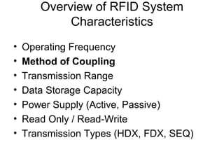
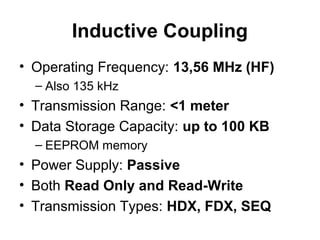
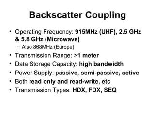
Overview of RFID System
            Characteristics
•   Operating Frequency
•   Method of Coupling
•   Transmission Range
•   Data Storage Capacity
•   Power Supply (Active, Passive)
•   Read Only / Read-Write
•   Transmission Types (HDX, FDX, SEQ)
Method of Coupling
• All RFID systems have two basic ways of
  exchanging information:
    (1) inductive coupling 
  or
    (2) electromagnetic backscatter
Inductive Coupling
• Operating Frequency: 13,56 MHz (HF)
  – Also 135 kHz
• Transmission Range: <1 meter
• Data Storage Capacity: up to 100 KB
  – EEPROM memory
• Power Supply: Passive
• Both Read Only and Read-Write
• Transmission Types: HDX, FDX, SEQ
Inductive Coupling


Inductive coupling means that the transponder and the
antenna are coupled by the magnetic flux through both
coils, much like a transformer. All the energy used in the
tag is drawn from the primary coil of the antenna.
Inductance
• Electromagnetic induction is the production of
  voltage across a conductor situated in a
  changing magnetic flux.


• Faraday found that the voltage produced around
  a closed path conductor is proportional to the
  rate of change of the magnetic flux through any
  surface bounded by that path.
    Faraday's law:
Oscillator
• A capacitor and an inductor connected together
  form an oscillator. Both capacitors and inductors
  store energy.
  A capacitor                                     an inductor
  stores energy                                   stores energy
  in the form of                                  in a magnetic field
  an electrostatic field

Once the capacitor is charged:
•The capacitor will start to discharge through the inductor. As it does,
 the inductor will create a magnetic field.
•Once the capacitor discharges, the inductor will try to keep the current
  in the circuit moving, so it will charge up the other plate of the capacitor.
•Once the inductor's field collapses, the capacitor has been recharged
(but with the opposite polarity), so it discharges again through the inductor.
Resonators
• The antenna coil of the transponder and the capacitor
  form a resonant circuit tuned to the transmission
  frequency of the reader. The voltage U at the
  transponder coil reaches a maximum due to
  resonance in the circuit.
   – This is way a radio receiver works


• The efficiency of power transfer between the antenna
  coil of the reader and the transponder is proportional
  to:
   – the operating frequency f
   – the number of windings n
   – the area A enclosed by the transponder coil
   – the angle of the two coils relative to each other
   – the distance between the two coils.
The rest of the picture
    • The energy in the coil can is harvested
      using diodes and capacitors (C2) to rectify
      the current.

LC circuit
oscillator
Method of Coupling
• All RFID systems have two basic ways of
  exchanging information:
    (1) inductive coupling
  or
    (2) electromagnetic backscatter 
Backscatter Coupling
• Operating Frequency: 915MHz (UHF), 2.5 GHz
  & 5.8 GHz (Microwave)
    – Also 868MHz (Europe)
•   Transmission Range: >1 meter
•   Data Storage Capacity: high bandwidth
•   Power Supply: passive, semi-passive, active
•   Both read only and read-write, etc
•   Transmission Types: HDX, FDX, SEQ
What is backscatter
• Electromagnetic backscatter is quite similar to
  radars.
• Depending on its characteristics, an antenna
  reflects part of an incoming electromagnetic
  wave back to the sender.
• Electromagnetic wave are reflected by most
  objects that are larger than half the wavelength.
• The efficiency of reflection is particularly large
  for antennas that are in resonance with the
  incoming waves.
   – The short wavelengths of UHF facilitate the
     construction of antennas with smaller dimensions and
     greater efficiency.
Far field not near field
• Opposite to inductive coupling, electromagnetic
  backscatter works beyond the near field.
• The energy available at the transponder is found
  by calculating the free space path loss aF between
  the reader and the transponder.
  aF = −147.6 + 20 log(r) + 20 log(f ) − 10 log(GT) − 10 log(GR)
How it works
• The power reflected from the
  transponder is radiated into
  free space. A small proportion
  of this (free space attenuation)
  is picked up by the reader’s
  antenna.
• The reflected signal travels
  into the antenna connection of
  the reader in the backwards
  direction and can be
  decoupled using a directional
  coupler.

Rfid coupling

  • 1.
    Overview of RFIDSystem Characteristics • Operating Frequency • Method of Coupling • Transmission Range • Data Storage Capacity • Power Supply (Active, Passive) • Read Only / Read-Write • Transmission Types (HDX, FDX, SEQ)
  • 2.
    Method of Coupling •All RFID systems have two basic ways of exchanging information: (1) inductive coupling  or (2) electromagnetic backscatter
  • 3.
    Inductive Coupling • OperatingFrequency: 13,56 MHz (HF) – Also 135 kHz • Transmission Range: <1 meter • Data Storage Capacity: up to 100 KB – EEPROM memory • Power Supply: Passive • Both Read Only and Read-Write • Transmission Types: HDX, FDX, SEQ
  • 4.
    Inductive Coupling Inductive couplingmeans that the transponder and the antenna are coupled by the magnetic flux through both coils, much like a transformer. All the energy used in the tag is drawn from the primary coil of the antenna.
  • 5.
    Inductance • Electromagnetic inductionis the production of voltage across a conductor situated in a changing magnetic flux. • Faraday found that the voltage produced around a closed path conductor is proportional to the rate of change of the magnetic flux through any surface bounded by that path. Faraday's law:
  • 6.
    Oscillator • A capacitorand an inductor connected together form an oscillator. Both capacitors and inductors store energy. A capacitor an inductor stores energy stores energy in the form of in a magnetic field an electrostatic field Once the capacitor is charged: •The capacitor will start to discharge through the inductor. As it does, the inductor will create a magnetic field. •Once the capacitor discharges, the inductor will try to keep the current in the circuit moving, so it will charge up the other plate of the capacitor. •Once the inductor's field collapses, the capacitor has been recharged (but with the opposite polarity), so it discharges again through the inductor.
  • 7.
    Resonators • The antennacoil of the transponder and the capacitor form a resonant circuit tuned to the transmission frequency of the reader. The voltage U at the transponder coil reaches a maximum due to resonance in the circuit. – This is way a radio receiver works • The efficiency of power transfer between the antenna coil of the reader and the transponder is proportional to: – the operating frequency f – the number of windings n – the area A enclosed by the transponder coil – the angle of the two coils relative to each other – the distance between the two coils.
  • 8.
    The rest ofthe picture • The energy in the coil can is harvested using diodes and capacitors (C2) to rectify the current. LC circuit oscillator
  • 9.
    Method of Coupling •All RFID systems have two basic ways of exchanging information: (1) inductive coupling or (2) electromagnetic backscatter 
  • 10.
    Backscatter Coupling • OperatingFrequency: 915MHz (UHF), 2.5 GHz & 5.8 GHz (Microwave) – Also 868MHz (Europe) • Transmission Range: >1 meter • Data Storage Capacity: high bandwidth • Power Supply: passive, semi-passive, active • Both read only and read-write, etc • Transmission Types: HDX, FDX, SEQ
  • 11.
    What is backscatter •Electromagnetic backscatter is quite similar to radars. • Depending on its characteristics, an antenna reflects part of an incoming electromagnetic wave back to the sender. • Electromagnetic wave are reflected by most objects that are larger than half the wavelength. • The efficiency of reflection is particularly large for antennas that are in resonance with the incoming waves. – The short wavelengths of UHF facilitate the construction of antennas with smaller dimensions and greater efficiency.
  • 12.
    Far field notnear field • Opposite to inductive coupling, electromagnetic backscatter works beyond the near field. • The energy available at the transponder is found by calculating the free space path loss aF between the reader and the transponder. aF = −147.6 + 20 log(r) + 20 log(f ) − 10 log(GT) − 10 log(GR)
  • 13.
    How it works •The power reflected from the transponder is radiated into free space. A small proportion of this (free space attenuation) is picked up by the reader’s antenna. • The reflected signal travels into the antenna connection of the reader in the backwards direction and can be decoupled using a directional coupler.