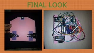
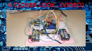
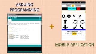
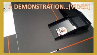
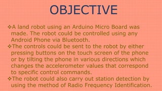
The document outlines the creation of a land robot controlled via Bluetooth using an Arduino microcontroller, which can be maneuvered through touch buttons or by tilting an Android phone. It details the components used, including DC motors, an RFID reader for station detection, and the assembly process of the robot's structure from corrugated plastic. The document also highlights the technical specifications of the Arduino board and motor driver used in the project.

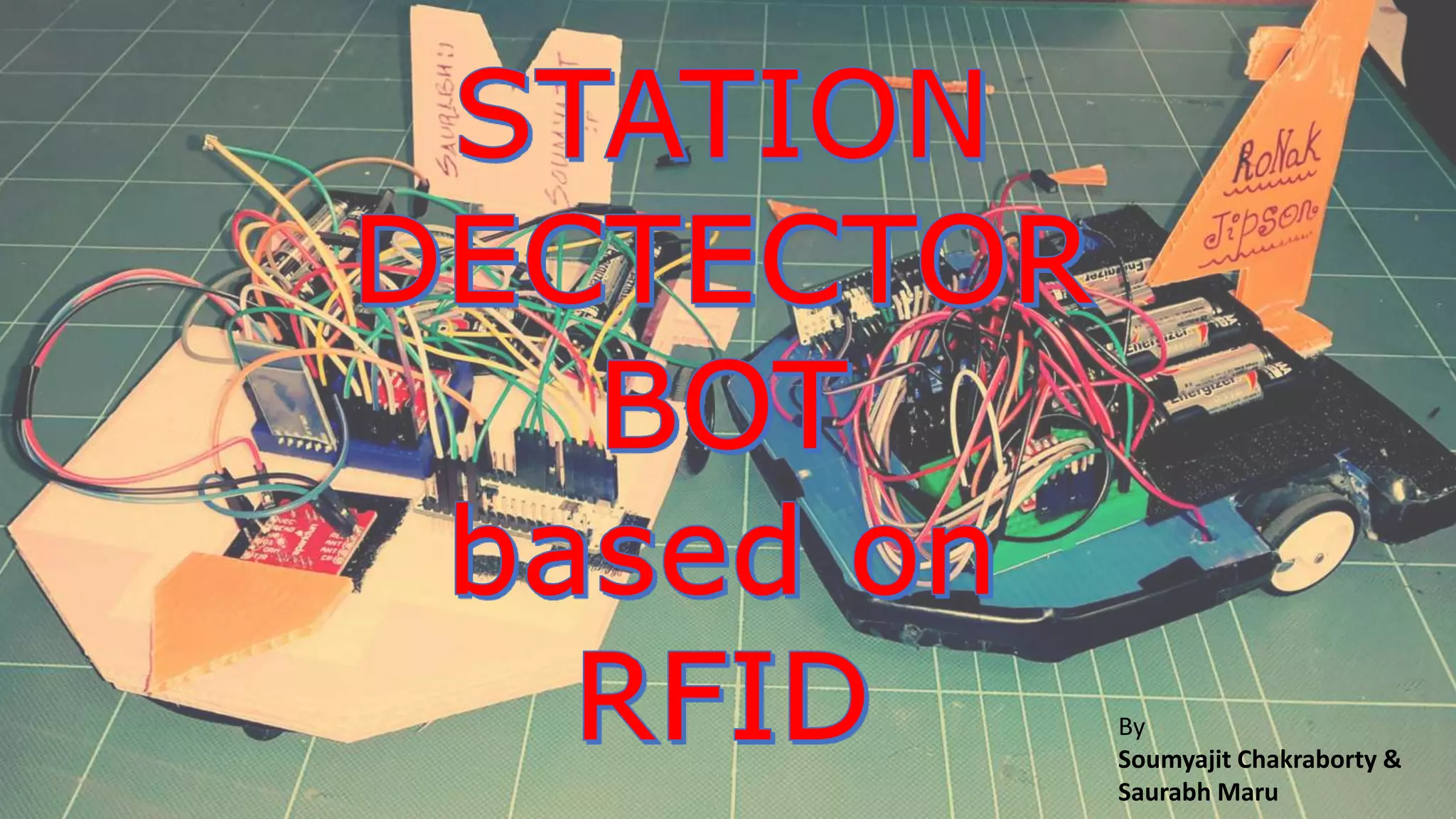
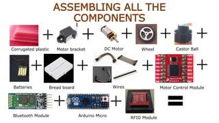
![COMPONENTS REQUIRED
Corrugated Plastic boards [4]
Wheels [2]
DC Motors [2]
Motor Mounting Brackets [2]
Arduino Micro board [1]
Motor Driver (TB6612FNG) [1]
Bluetooth Module HC-05 (FC-114) [1]
Castor Ball [1]
Jumper Cables and Header Pins
AAA Batteries with cases [6]
Bread Board [1]
RFID Reader (ID-20) together with SEN-13030 breakout board [1]
Android Phone [1]
Soldering Iron
Glue, Velcro straps, Wire stripper, Pen knife](https://image.slidesharecdn.com/rfidbot-170215174342/85/RFID-Bot-3-320.jpg)