Download to read offline
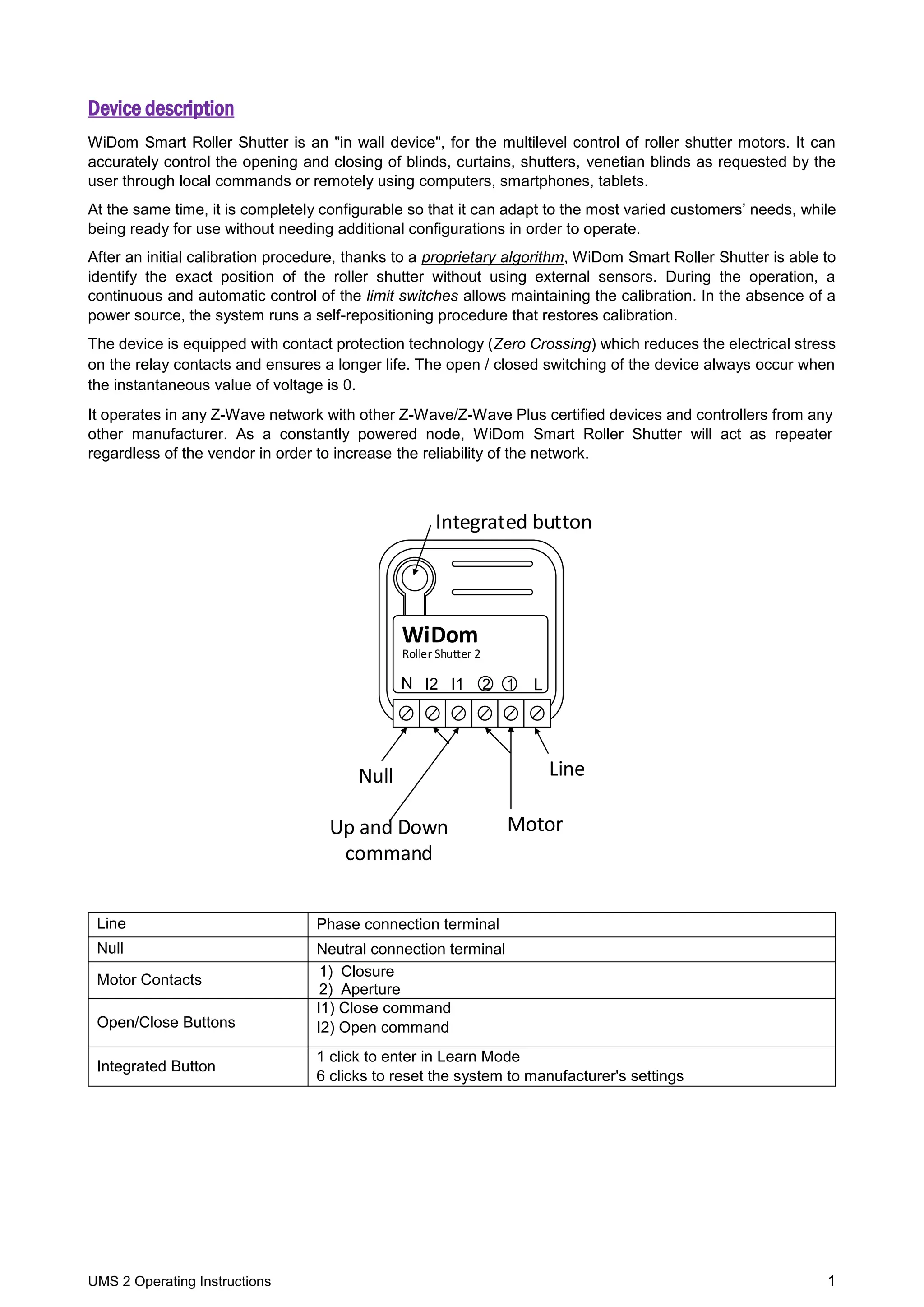
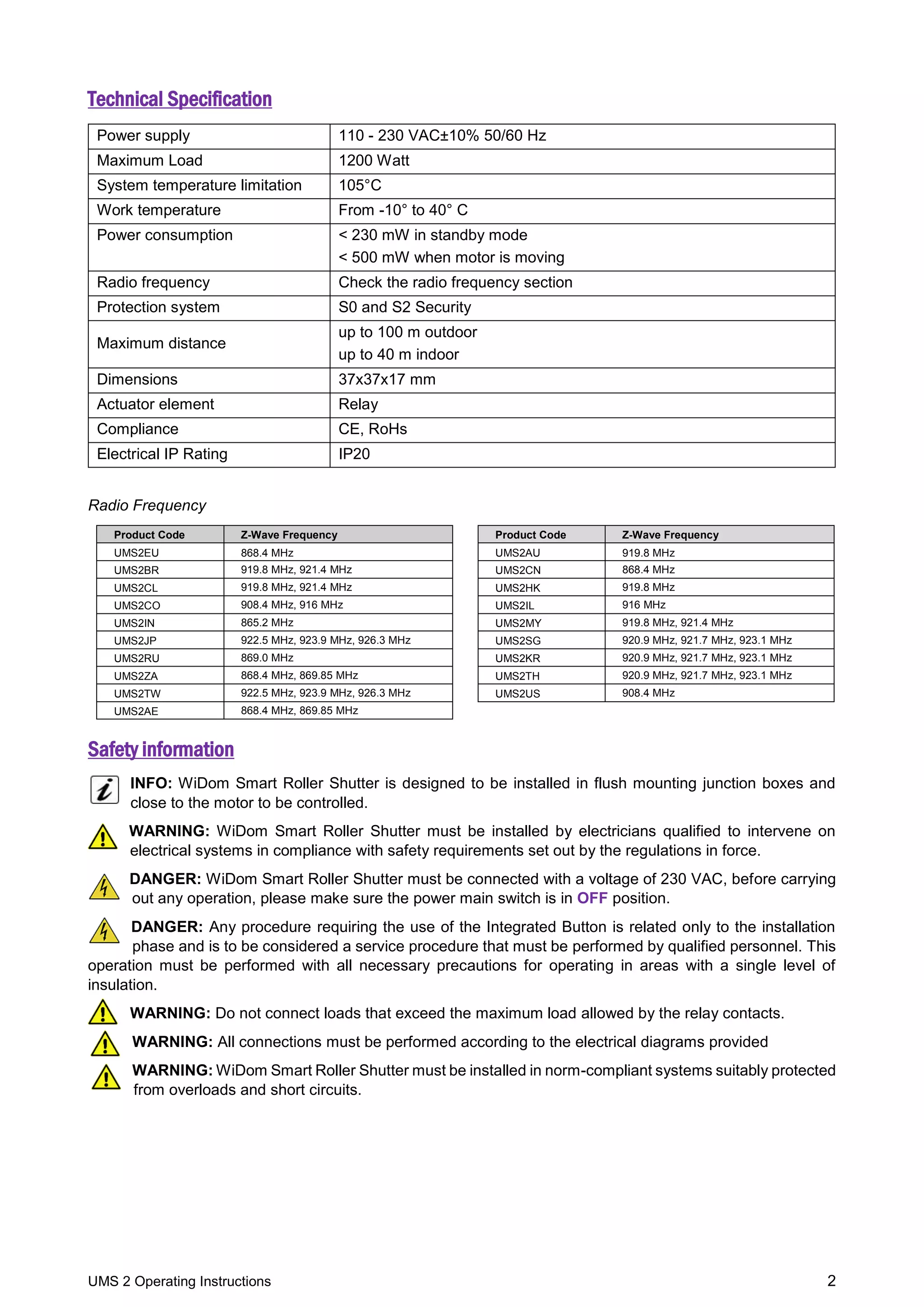
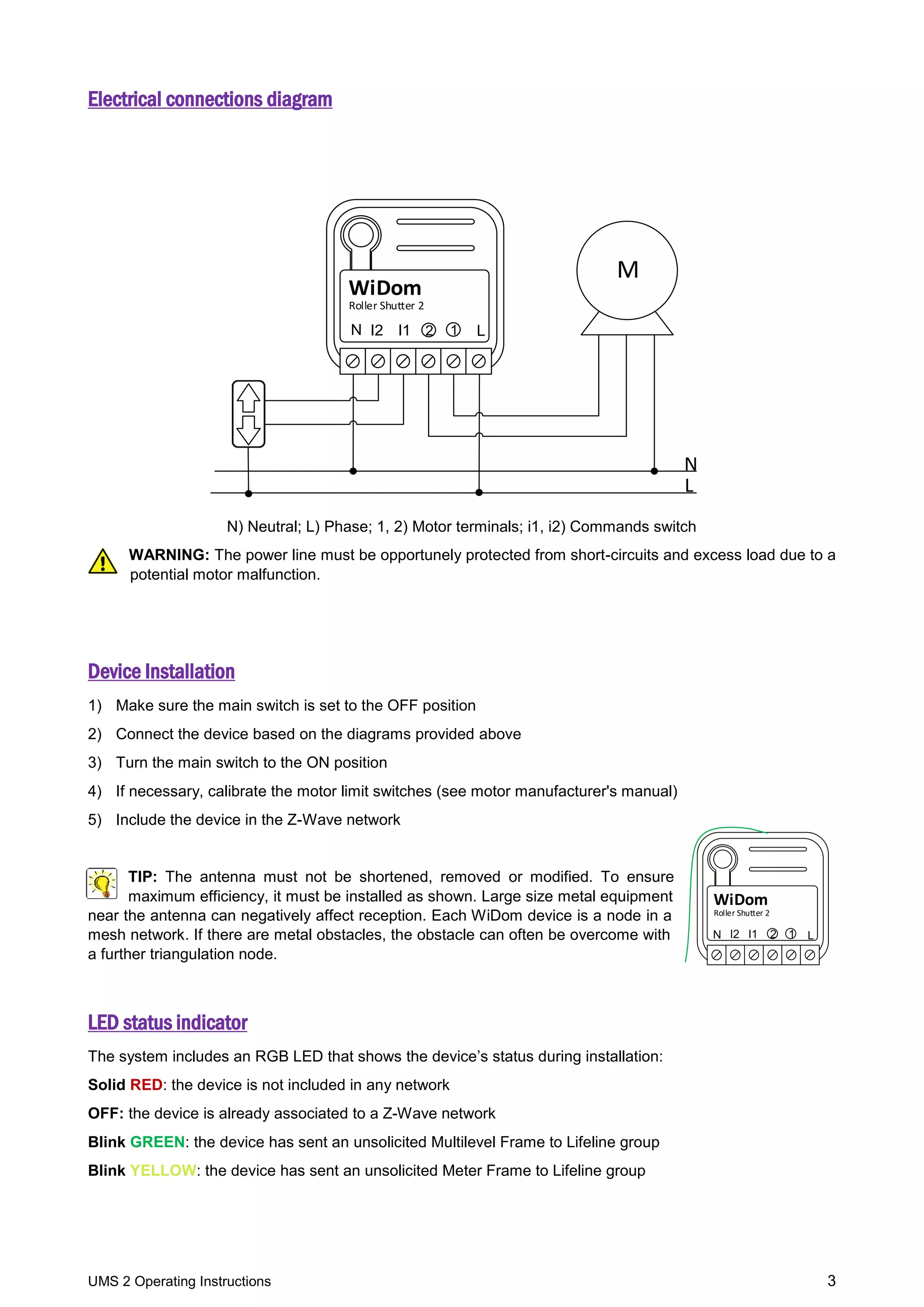
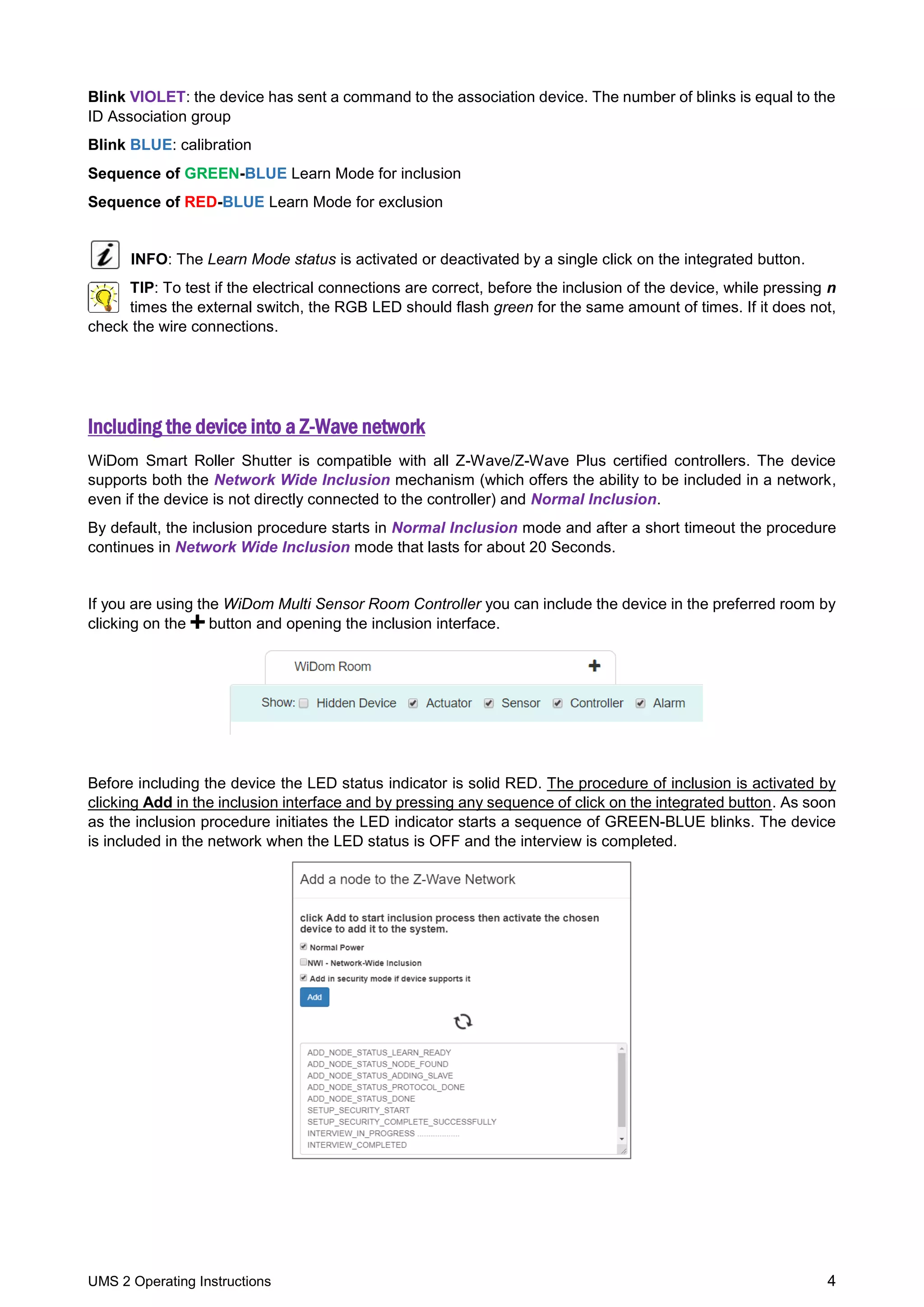
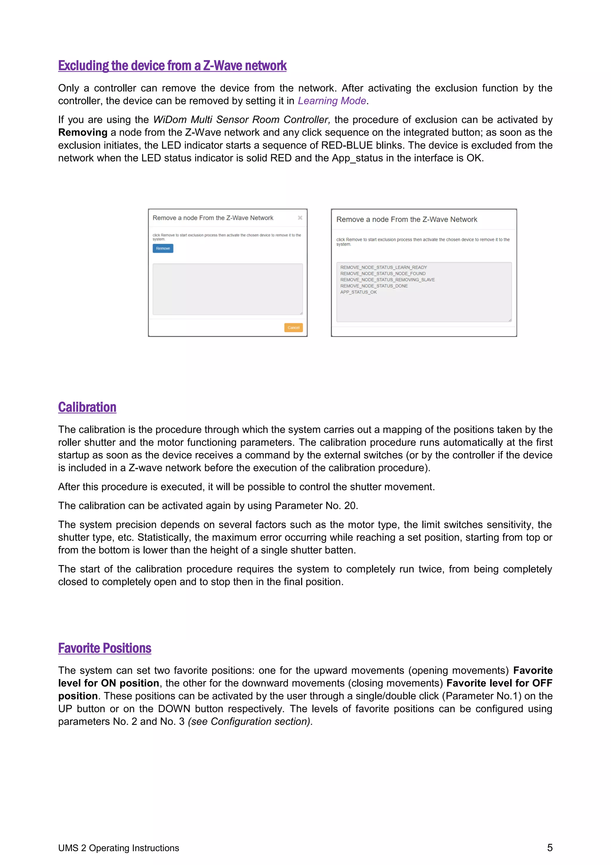
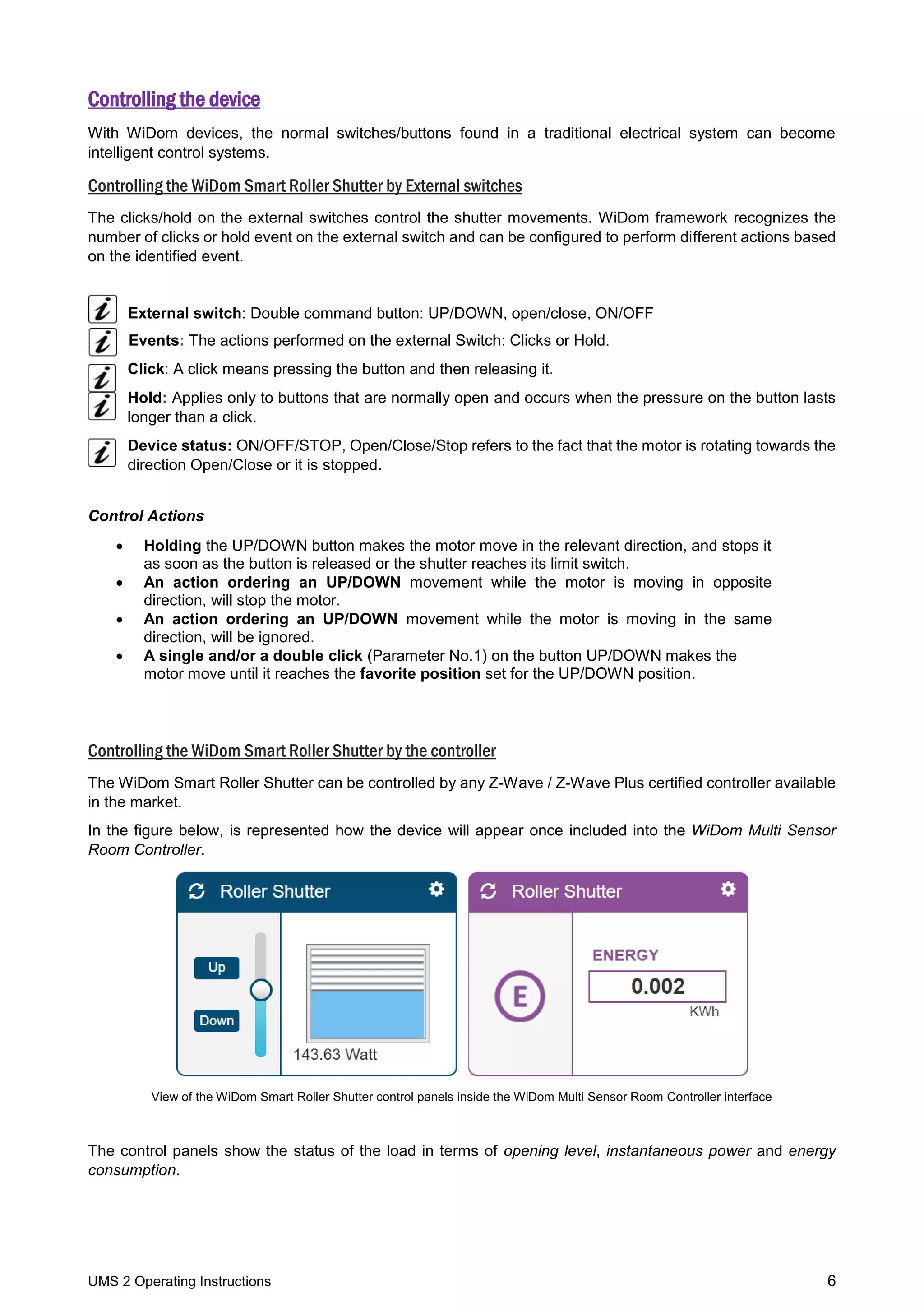
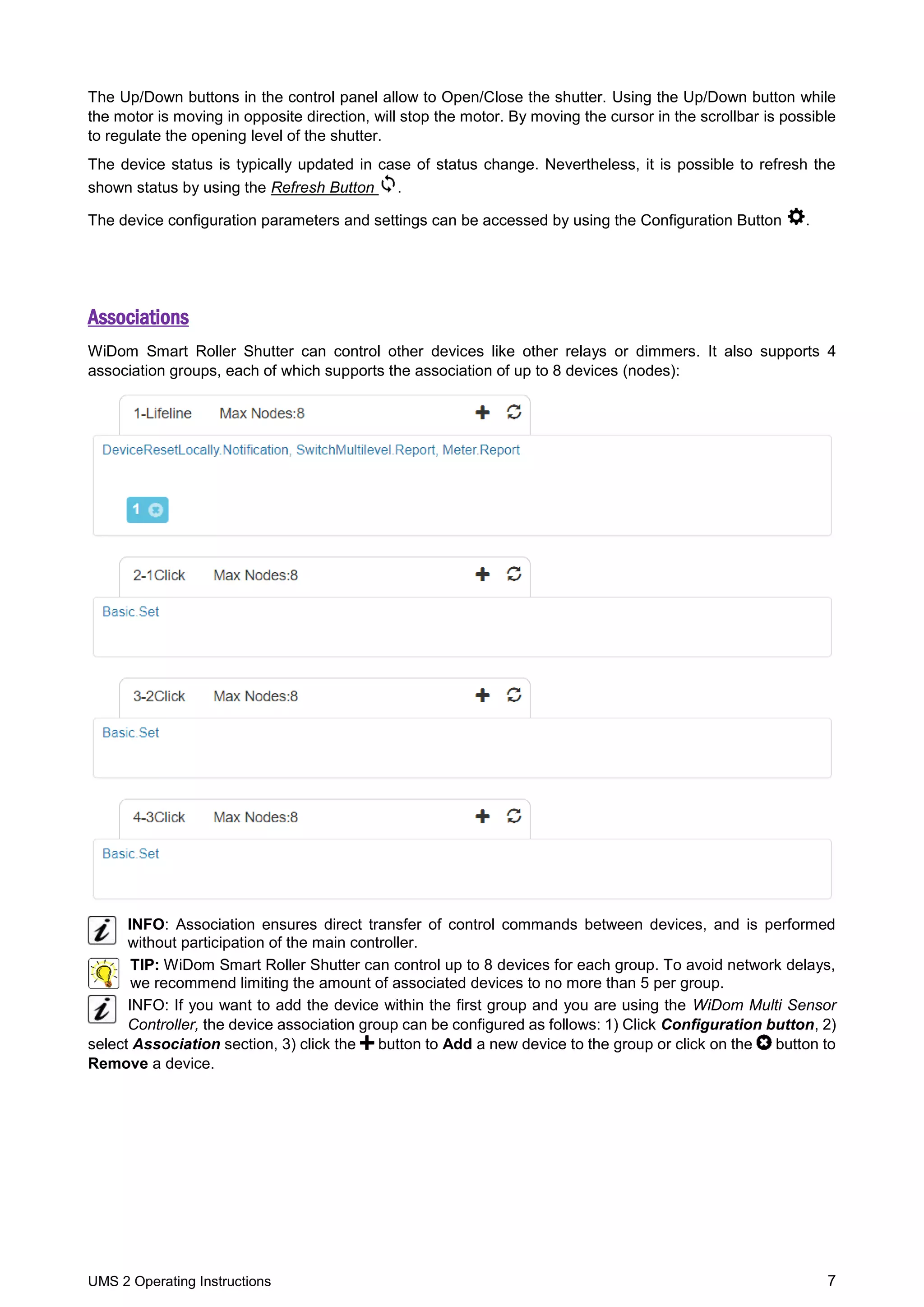
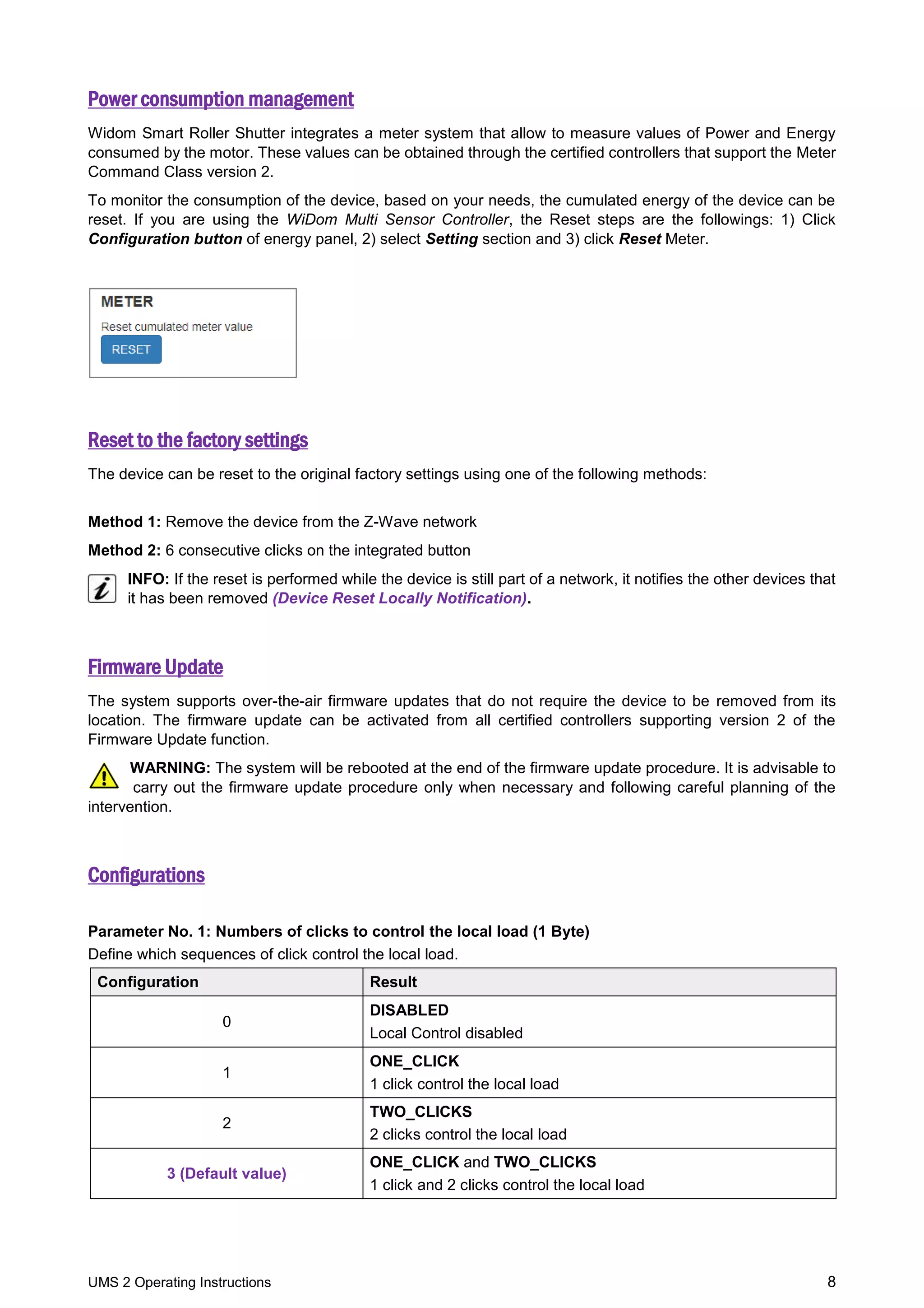
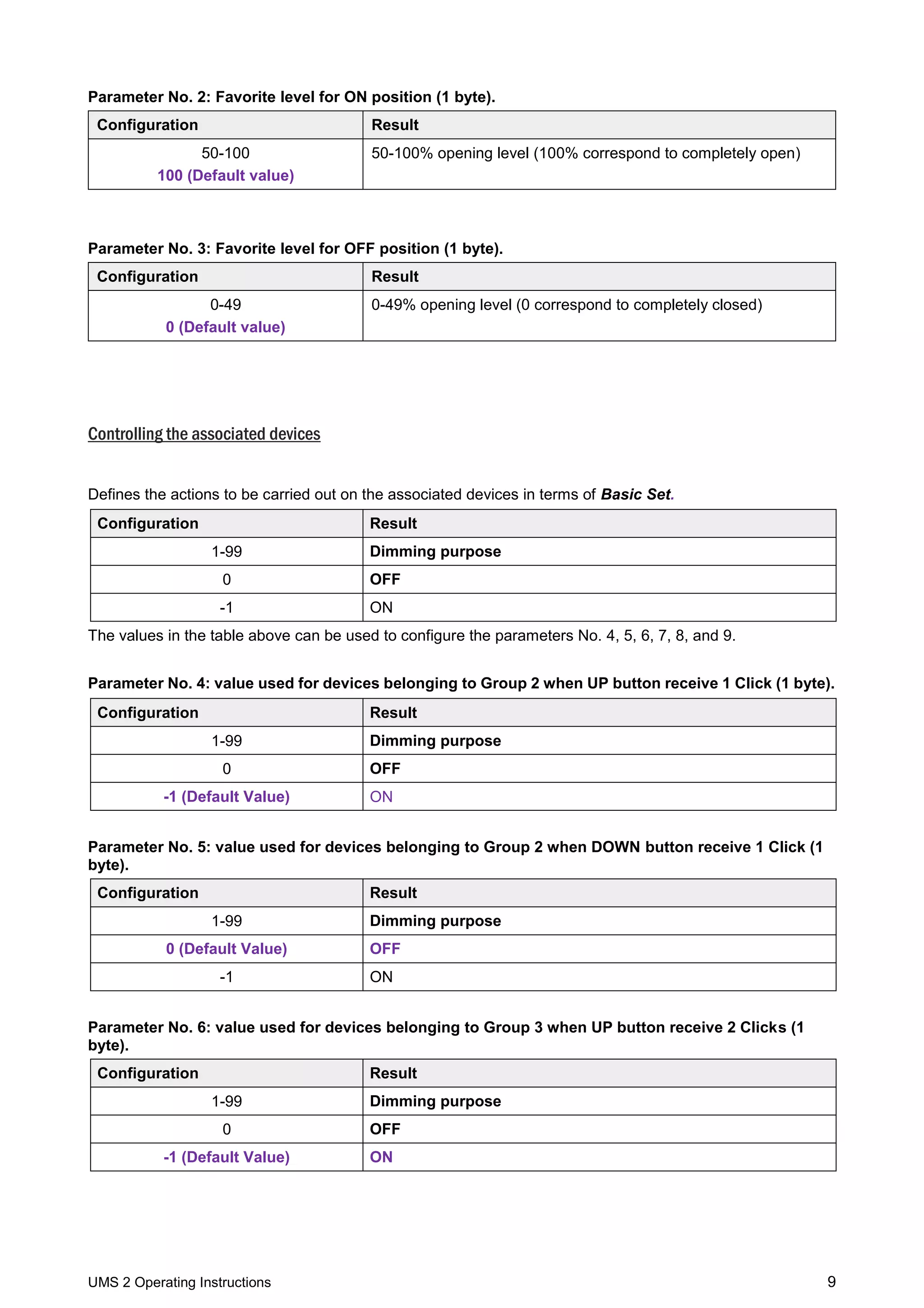
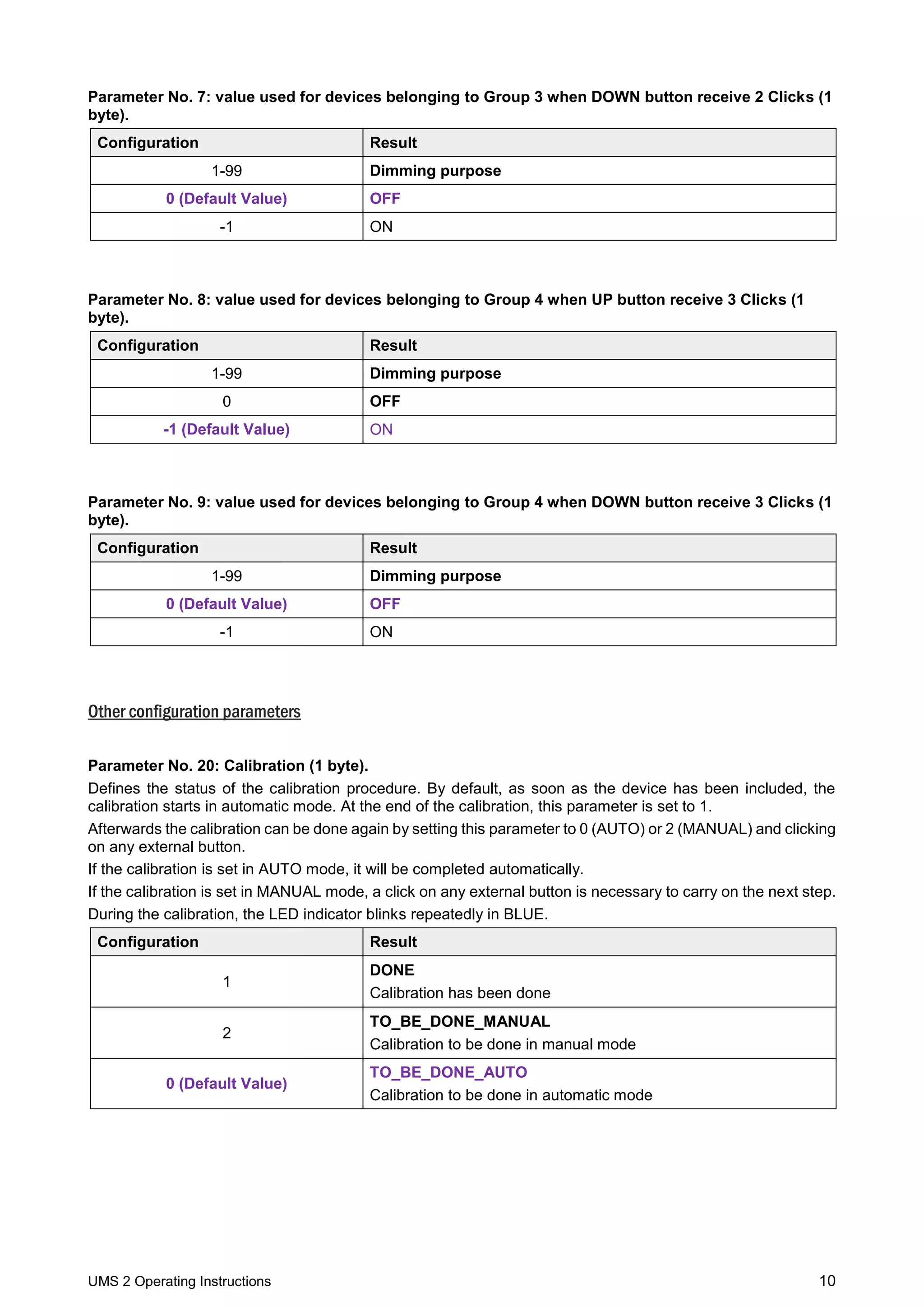
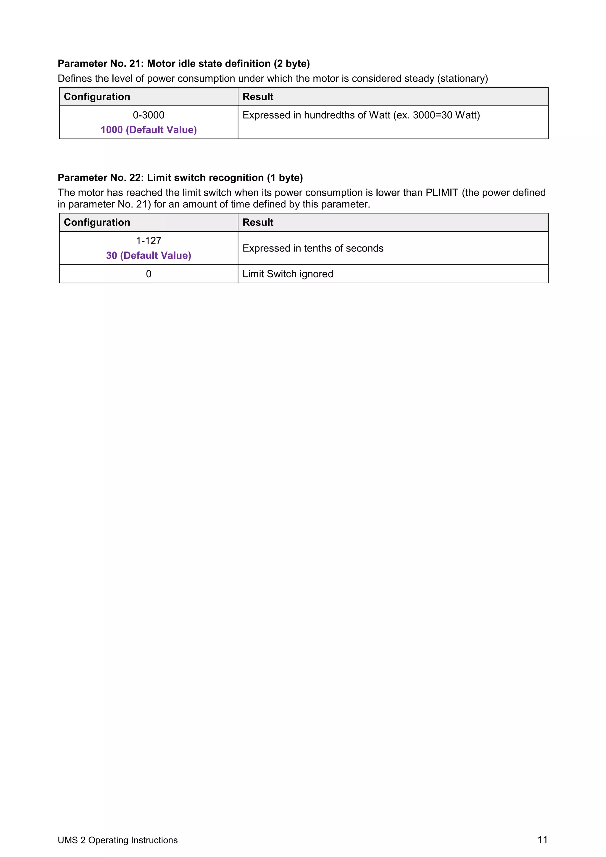

The document provides operating instructions for the Widom Smart Roller Shutter, detailing its device description, technical specifications, safety information, and installation procedures. It explains how to include and exclude the device in a Z-Wave network, perform calibration, set favorite positions, and manage power consumption. The instructions also cover control mechanisms using external switches and controllers, as well as configuration parameters for customization.


