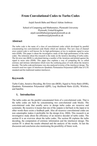
This document discusses turbo codes, which are a type of error correction code built by parallel concatenating two convolutional code blocks. It focuses on investigating the iterative decoding of turbo codes. The bit error rate is calculated over multiple iterations of decoding and plotted against signal to noise ratio. Quadratic permutation polynomial and random interleavers are analyzed. Results show turbo codes with a memory of 3 and 1280 bit interleaver achieve the best performance, reaching a bit error rate of 10-5 at -1.2 dB after 10 iterations of decoding.
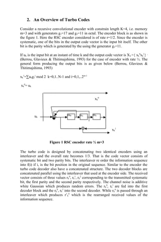
![If s is the present state at a trellis level, then the two next states possible are s0
’
and s1
’
corresponding to a 0 and 1 transition. The final decision is made from the LLR
calculated as below.(Lin, 2004)
LLR= log[(∑αkβk+1δk(1))/(∑ αkβk+1δk(0))].
Fig 4. Iterative Turbo Decoder
The message bit is decoded as a 0 if LLR ≤ 0 and a 1 if LLR > 0.
3.1. Intrinsic Information
The LLR can be split into its three components as shown below.
LLR1
(uk)= Le
1
(uk)+La
1
(uk)+ Le
2
(uk)
LLR1
(uk)= log1[P(uk=1/rk)/P(uk=0/rk)] + log[P(1)/P(0)]+ log1[P(uk=1/rk)/P(uk=0/rk)]
The intrinsic information is one of those components which is the probability of kth
bit calculated from the channel information. The intrinsic information is represented
as La(uk) which is calculated from the bit probabilities P1
1
(k) and P1
0
(k) for the first
decoder block.
P1
1
(k) = exp (-(rk
0
-(+1))/2*σ2
)
P1
0
(k) = exp (-(rk
0
-(-1))/2*σ2
) where σ2
is the variance.
The intrinsic information La (uk) = log[P1
1
(k)/ P1
0
(k)]
3.2. Extrinsic Information
I DI
I
Decoded value
Extrinsic information
Extrinsic information
(Channel L value + Extrinsic
from MAP1)
Channel value for
parity bit y0
from
encoder2
Channel value for
the systematic
output
Channel value for
parity bit y1
from
encoder2
MAP1
MAP2
(Channel L value + Extrinsic
from MAP2)](https://image.slidesharecdn.com/76d03690-9d2b-4625-bc35-7d8c9b67e799-150611150336-lva1-app6892/85/Research-Paper-4-320.jpg)
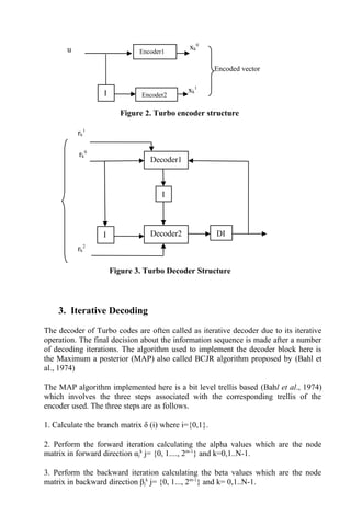
![The extrinsic information is the knowledge about the corresponding parity bits
transmitted. By passing the extrinsic information form decoder 1 to decoder 2, it
means the information about the first parity bit is passed to decoder 2 so that the
decoder 2 can compute an improved LLR in the following iterations. The extrinsic
information can be extracted by the LLR as follows,
Le
1
(uk)= LLR (k)- La
1
(uk) – Le
2
(uk)
In other sense the extrinsic information can be considered as the equation below.
Le
1
(uk)= log [ P(uk=1/rk
1
)/P(uk=0/rk
1
)]
3.2. Interleaver
The interleaver types considered in this research is the quadratic permutation
polynomial, random interleaver and row-column interleaver. The permutation
polynomials of three different lengths are used(Rosnes, 2012) of lengths 512, 1024
and 1280. The row-column interleaver used is a square matrix. The information bits
are written row by row into the matrix and read pseudo randomly(Fragouli & Wesel,
1999). The random interleaver is a random number generator in which the bit
positions to be permuted are generated randomly.
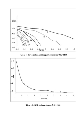
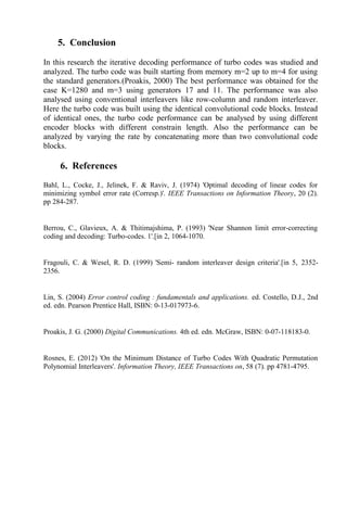
4. Results
The turbo code of rate 1/3 with memory m=3 is built using RSC encoders using
generators 17 and 11. The bit error rate (BER) is calculated at the end decoding and
plotted against the SNR. The decoding was done for a number of iterations. Using
memory m=3, in ten iterations BER 10-5
was obtained at SNR -1.2 dB. The figure 5
shows the graph plotting BER of turbo code using QPP interleaver. The BER found
to be constantly reducing in iteration. The figure 6 shows the BER constantly
reducing with increasing the number of iterations. The best BER value of range 10-5
was obtained in the ninth iteration at -0.4 dB.](https://image.slidesharecdn.com/76d03690-9d2b-4625-bc35-7d8c9b67e799-150611150336-lva1-app6892/85/Research-Paper-5-320.jpg)