Downloaded 129 times


![digital solution which may be implemented without the need for new frequency allocations or
without disruption to the existing broadcasting infrastructure.
CHAPTER 1
INTRODUCTION
1.0 BACKGROUND
Frequency modulation (FM) is a technique for wireless transmission of information where the
frequency of a high frequency carrier is changed in proportion to message signal which contains
the information according to [1]. FM was invented and developed by Edwin Armstrong in the
1920’s and 30’s. Frequency modulation was demonstrated to the Federal Communications
Commission (FCC) for the first time in 1940, and the first commercial FM radio station began
broadcasting in 1945 [2]. FM is not a new concept. However, the concept of FM is essential to a
wide gamut of radio frequency wireless devices and is therefore worth studying. This seminar will
explain the design decisions that should be made in the process of design and construction of an
FM transmitter. The design has also been simulated. For a long time radio was the largest mass
media but in recent years it has lost a number of listeners. In contrast, total media consumption has
increased. Young people are abandoning traditional media and want to decide on where, when and
how they receive media content, for example via Internet and mobile telephones. Listeners are
most interested in easily being able to select radio stations, to have better sound quality and
audibility and to increase accessibility for people with visual and auditory impairments.
Listeners also want a wider range of radio channels over the whole country. Consumers ‘needs
must be met hence the need for advancements in the field of radio broadcast.
New technology creates the necessary conditions for improvements. This seminar also evaluates
the different technologies on the basis of questions like:
How well does the technology satisfy consumers’ needs?
What functionality does the technology offer?
How efficiently does the technology utilize the available spectrum?
What financial conditions are available for the technology?
Standardization policy for the technology.
1.1 OBJECTIVES
The objectives of this seminar are:
i. To review present-day FM transmitters and their limitations.
ii. To present some modern digital technologies that has been developed for effective FM
signal generation.](https://image.slidesharecdn.com/myreportoninbandonchannel-170331141132/75/Report-on-In-Band-On-Channel-8-2048.jpg)
![iii. To provide an overview of the Radio communicationissues that might be improved
through the use of Hybrid Digital Radio (HD Radio), Software Defined Radio
(SDR) and Cognitive Radio Systems (CRS).
iv. To accusatively compare these technologies.
1.2 SCOPE
This seminar covers the design of FM transmitters for quality audio transmission and explains
some of the modern trends in FM signal generation, highlighting their prospects. It also covers
the advantages these technologies offer over traditional radio broadcasting and brings to light
various distinguishing features possessed by these technologies.
1.3 SIGNIFICANCE
The rolethat radio plays in thesociety is an important issueto consider in discussionsabout
which technology can best distributeradio in thefuture. Thefact that radio has an
important rolein society can beclearly seen in thenumber of listeners. Despitetherisein
thetotal consumption of media, radio has lost a number of listeners according to a survey
reported in [3, pp. 40-49].
The medium of radio has many positivecharacteristics for listeners. It is:
i. Free from subscriptioncharges
ii. Simpleto use
iii. Possibleto listen to everywhere, including sparsely populated areas and whilein
motion in cars and trains.
iv. Possibleto listen to whiledoing something else
v. Important as a channel of information, especially in crises and catastrophes.
vi. An important medium for traffic information, shipping and mountain rescue.
Radio needs to be developed to satisfy theneeds of future consumers, hence
the need for this study.](https://image.slidesharecdn.com/myreportoninbandonchannel-170331141132/75/Report-on-In-Band-On-Channel-9-2048.jpg)
![1.4 REPORT OVERVIEW
Chapter oneprovides an overview of theseminar by giving description of thetopic.
Chapter two deals with FM transmitters, their drawbacks and how they are
overcome.
Chapter three covers modern radio transmission technologies: IBOC Hybrid Digital
(HD) Radio and Software Defined Radio (SDR); explaining their advantages,
limitations and how they enhance radio communication.
In chapter four, SDR and HD radio technologies werecompared with other radio
technologies. It also includes theconclusion.
CHAPTER 2
FM TRANSMITTERS
2.0 OVERVIEW
An FM Transmitter is a devicewhich generates frequency modulated signal. It is one
element of a radio system which, with theaid of an antenna, propagates an
electromagnetic signal [3]. Someof its applications include:
• Non-commercial broadcasting.
• Commercial broadcasting.
• Television audio.
• Public Service communications.
• Radio Service Communications.
• Point-to-point microwave links used by telecommunications
companies.](https://image.slidesharecdn.com/myreportoninbandonchannel-170331141132/75/Report-on-In-Band-On-Channel-10-2048.jpg)


![Poor frequency Accuracy: The transmitter must be on the exact
frequency that the receiver is expecting it to be. This is primarily
determined by the master reference oscillator.
Undesired Spurious Generation: The synthesizer must also minimize
spurious signalswhich corrupt thetransmitted signaland makereceiver
demodulation difficult.
• NOISE
Noise is typically narrow spikes of voltage with lots of harmonics and other high
frequency components that add to a signal, interferes with it and sometimes,
completely obliterates the signal information. [4]
FM systems are generally better at rejecting noise than AM systems. Poor design
resultsinexcessivePhaseNoise,a “smearing”oftheTransmitterLocalOscillatorsignal
that the Receiver interprets as noise, making accurate demodulation difficult and a
corresponding high probabilityof error. Noisecan also result frompoorpower supply
regulation and/or filtering.
2.4 FM TRANSMITTER OPTIMISATION
Having discussed the drawbacks of an FM transmitter, techniques employed in
mitigating them include:](https://image.slidesharecdn.com/myreportoninbandonchannel-170331141132/75/Report-on-In-Band-On-Channel-15-2048.jpg)

![frequency noises. A simplehigh-pass filter can serveas a transmitter’spre-emphasis
circuit. A sample pre-emphasis circuit is shown below:
Fig 2.6: Pre-emphasis Circuit.
• Phase Locked Loop (PLL):
PLL is basically a closed loop frequency control system whosefunctioning is based on
thephase sensitivedetection of phasedifferencebetween theinput and output
signals of thecontrolled oscillator according to [6]. It is used to lock thecentral
frequency of a transmitter to a stablecrystalreferencefrequency. A basic phase
locked loop consists of three(3) elements:
Phase Comparator:This circuit block within thePLL compares thephase
of two signals and generates a voltageaccording to thephase
difference between thetwo signals.](https://image.slidesharecdn.com/myreportoninbandonchannel-170331141132/75/Report-on-In-Band-On-Channel-17-2048.jpg)

![CHAPTER 3
MODERN RADIO TRANSMISSION TECHNOLOGIES
3.0 In-Band On-Channel (IBOC) HYBRID DIGITAL (HD) RADIO
HD Radio IBOC (In-Band On-Carrier) is a method of broadcasting digital radio signals on the
same channel, and at the same time as the conventional AM or FM signal. iBiquity Digital
Corporation developed this solution in response to the need for a digital system that didn’t require
additional frequency bands which were not available. IBOC is an evolutionary system, allowing
increased performance as the number of digital receivers increase. [8]
Renee [7], points out that HD Radio is a new technology that enables AM and FM Radio stations
to broadcast their programs digitally, a tremendous technological leap from today's familiar analog
broadcasts. HD Radio is the only current digital radio solution which operates in the existing FM
band. It allows the transmission of the existing unchanged FM analog signal along with digital
subcarriers which provide CD quality audio – as well as the possibility of multiple digital channels.
Both the conventional FM analog signal and the digital sidebands fit within the typical spectral
mask allocated for FM stations (i.e. same spot on the FM dial). [9]
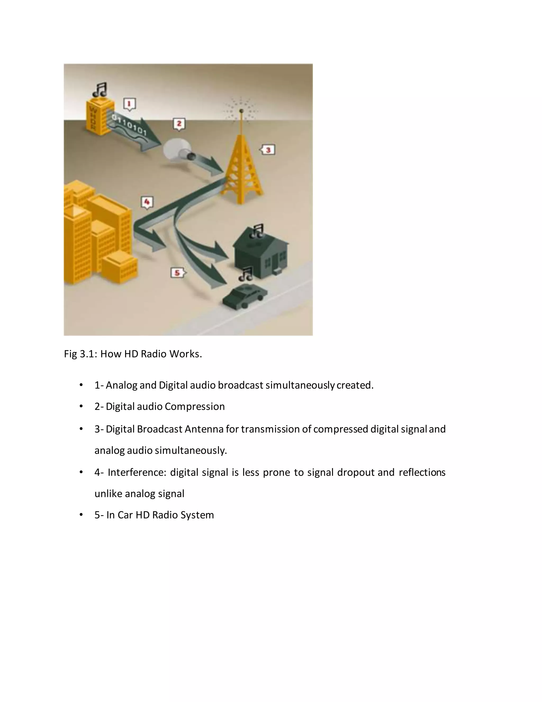
3.1WORKING PRINCIPLEOF HD RADIO
Firstly, the radio station simultaneously creates a digital and analog audio broadcast.
The digital signal is then compressed for multicasting and enhanced services while the analog
signal is left untouched, both of which are transmitted at the same time. Signal travels through the
broadcast area while receivers shoot trough bounced signals to enhance clarity.](https://image.slidesharecdn.com/myreportoninbandonchannel-170331141132/75/Report-on-In-Band-On-Channel-19-2048.jpg)


![CHAPTER 4
4.0 Challenges
AM IBOC in the United States still faces some serious technological challenges of its own,
including nighttime interference with other stations iBiquity was previously using PAC (also used
at a higher bitrate in Sirius satellite radio, Digital Audio Radio Service), but in August 2003 a
switch to HDC (based-upon ACC) was made to rectify these problems. HDC has been customized
for IBOC, and it is also likely that the patent rights and royalties for every transmitter and receiver
can be retained longer by creating a more proprietary system. Digital Radio Mondale is also
developing an IBOC system, likely to be used worldwide with AM shortwave radio, and possibly
with broadcast AM and FM. Neither of those have been approved yet for ITU region 2 (the
Americas). The system, however, unlike HD Radio, does not permit the existing analog signal and
the digital signal to live together in the same channel. DRM requires an additional channel to
maintain both signals.
Both AM and FM IBOC signals cause interference to adjacent-channel stations, but not within the
station’s interference-free protected contours designated by the U.S. Federal Communications
Commission (FCC). It has led to derogatory terms such as IBAC (In-band adjacent-channel) and
IBUZ (since the interference sounds like a buzz.) The range of a station on an HD Radio receiver
is somewhat less than its analog signal. However, in June, 2008, a group of US broadcasters and
equipment manufacturers requested that the U.S. FCC increase the permissible FM IBOC power
from 1% (currently) to a maximum of 10% of the analog power. On January 29, 2010, the FCC
approved the request.[10] In addition, tropospheric ducting and e-skip can reduce the range of the
digital signal, as well as the analog.
In-band on-channel digital radios using iBiquity's standard are being marketed under the brand
"HD Radio" to highlight the purported quality of reception. As of June 2008, over 60 different
receiver models have been made, and stations have received blanket (no longer individual and
experimental) authorization from the U.S. FCC to transmit in a multiplexed multichannel mode on
FM. Originally, the use of HD Radio transmission on AM was limited to daytime only, and not
allowed at night due to potential problems with sky wave radio propagation. The FCC lifted this
restriction in early 2007. DRM, however, is being used across Europe on shortwave, which is
entirely AM sky wave without issue. With the proper receiver, many of those stations can be heard
in North America as well, sans the analog signal.
4.1 Conclusions
FM transmission is an area of communication that is always moving with technological
advancements. As the new digital radios become more available, dramatic improvements will be
heard by listeners. Careful design of the new transmissions systems will pay off with reduced costs](https://image.slidesharecdn.com/myreportoninbandonchannel-170331141132/75/Report-on-In-Band-On-Channel-26-2048.jpg)
![and improved performance and reliability. HD Radio FM is both robust and efficient in the difficult
mobile environment, SDR provides flexibility and Cognitive Radio will definitely define a whole
new level of FM transmission.
References
[1] Russell Mohn, “A Three Transistor Discrete FM Transmitter,” ELEN 4314
Communications Circuits - Design Project, pp. 1, April 2007.
[2] “FM broadcasting in theUnited States” Ibiquity /ATTC/ Dynasat FM IBOC Test Data Report,
Aug 2001
[3] T.U.M Swarna kumara et al., “A Mini Project on SimpleFM-Transmitter”.
[4] E. F. Louis, Principles of Electronic CommunicationSystems. McGraw-Hill, 2008
[5] “The Futureof Radio”. The Swedish Radio and TV Authority, 2008.
[6] Holm, Steve (2007). "Lydkvalitetet i DAB digitalradio". Digitale Utgivelser ved UiO. Retrieved
2009-01-03. (Norwegian).
[7] C. Renee, “An Industrial WhitePaper: HDRadio”
[8] C. W. Kelly, “Digital HD Radio AM/FM Implementation Issues”, USA.
[9] C. W. Kelly, “HD-Radio: Real World Results in Asia”, USA.
[10] Groome B., “HD Radio (I.B.O.C)”,TMH Publication 3rd
edition 1999.
[11] Robinson, David J. M. (2002-07-09). "DAB sound quality". OFCOM: Regulation in digital
broadcasting: DAB digital radio bitrates and audio quality; Dynamic range compression and
loudness. Retrieved 2009-01-03.](https://image.slidesharecdn.com/myreportoninbandonchannel-170331141132/75/Report-on-In-Band-On-Channel-27-2048.jpg)

The document is a seminar report on IBOC (In-Band On-Channel) technology. It discusses FM transmitters and their limitations. It then provides an overview of IBOC technology, which allows digital radio signals to be broadcast simultaneously with analog signals on the same FM channel. IBOC utilizes additional digital subcarriers or sidebands to multiplex digital information onto existing FM broadcasts without requiring new frequencies. This allows for multiple program channels but can reduce stereo bandwidth on FM. Stations can eventually transition to being fully digital. IBOC focuses on a digital transition that works within existing broadcasting infrastructure.