
Downloaded 148 times

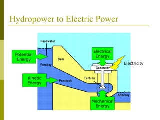
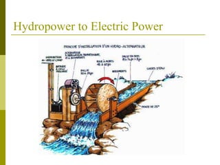
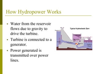
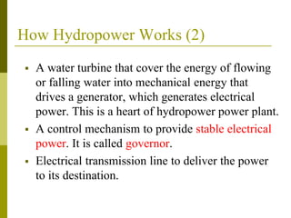
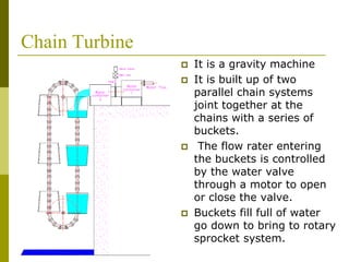
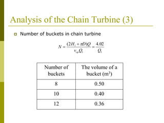
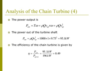
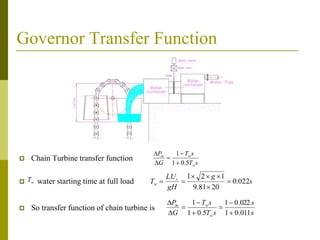
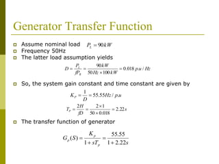
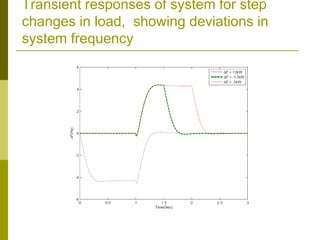

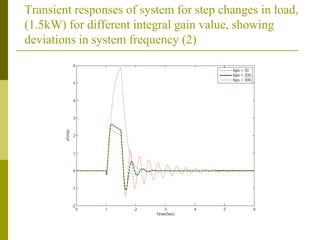
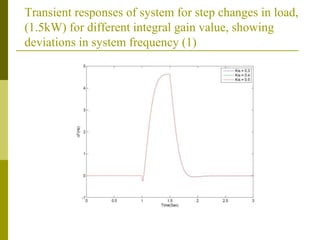
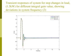

This document discusses micro hydroelectric power plants that use chain turbines. It provides an overview of how hydropower works by converting the kinetic energy of moving water into electrical energy. It then analyzes the specific design and operation of chain turbines, which use a series of buckets on parallel chains to capture water flow. The document also examines the use of governors to provide stable electrical output from these plants by controlling water flow based on generator speed. It analyzes the transient responses of a sample system to changes in load and discusses ways to improve governor performance.


![[0] final - report hydroelectric power plant](https://cdn.slidesharecdn.com/ss_thumbnails/0-final-reporthydroelectricpowerplant-110524065944-phpapp01-thumbnail.jpg?width=640&height=640&fit=bounds)


