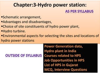
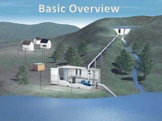
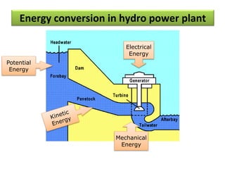
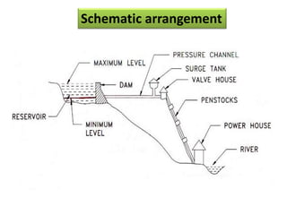
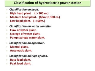
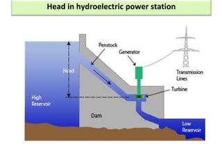
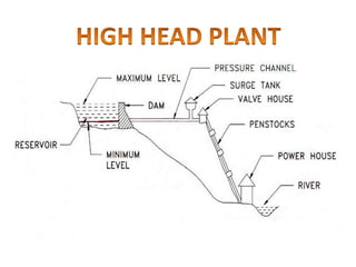
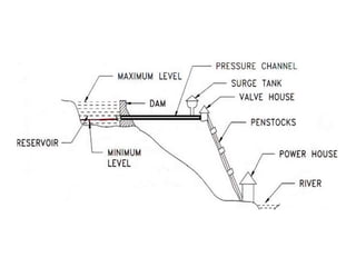
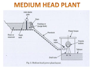
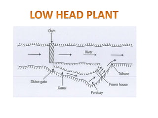
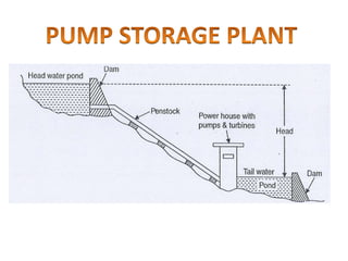
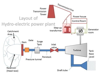
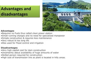
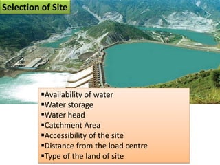
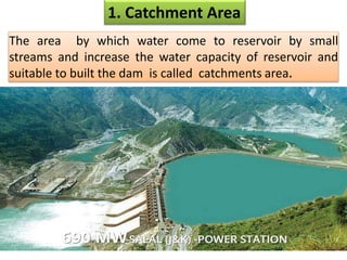
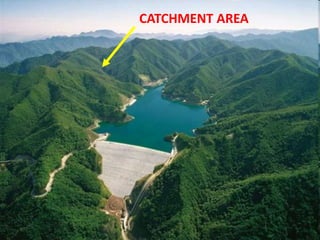
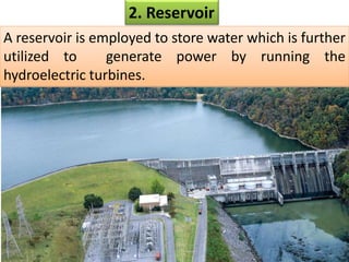
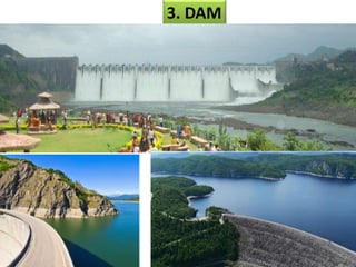
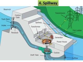
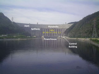
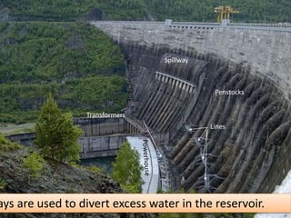
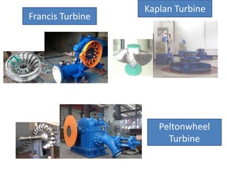
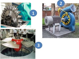
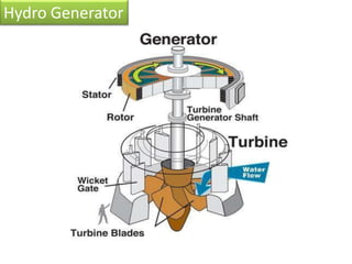
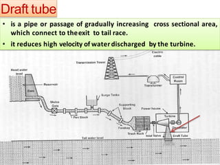
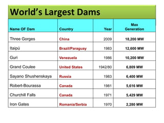
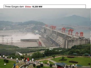
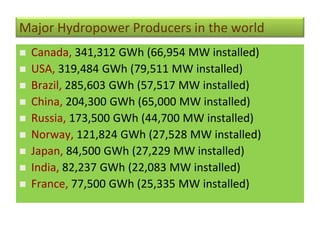
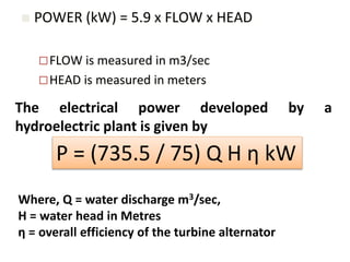
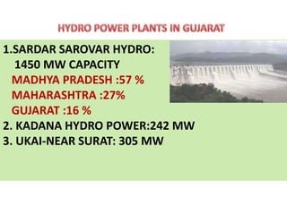
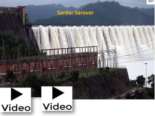
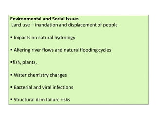
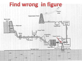
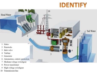
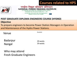
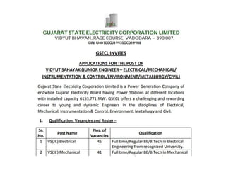
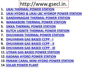
Thursday,January10, 2019
Sub: Electrical Power Generation
CH-2: Hydro Power Station
Chapter:3-Hydro power station:
Schematic arrangement,
Advantages and disadvantages,
Choice of site constituents of hydro power plant,
Hydro turbine.
Environmental aspects for selecting the sites and locations of
hydro power stations
45
Thermal power plant
Coal 1,95,000 MW 56%
Gas
25,000 MW 7%
Oil
800 MW 0.2%
Total Thermal 2,20,800 MW 63.2%
Hydro (Renewable) 45000 MW 12.8%
Nuclear 7000 MW 2.0%
RES* (MNRE) 72000 MW 22%
Power plant data- ALL INDIA as on Dec-2018
Total 3,46,048 MW
Energy conversion in hydro power plant
Potential
Energy
Electrical
Energy
Mechanical
Energy
Schematic arrangement
 Classification on head.
 High head plant (  300 m.)
 Medium head plant. (60m to 300 m.)
 Low head plant. (  60m.)
 Classification on water condition
 Flaw of water plant.
 Storage of water plant.
 Pump storage water plant.
 Classification on operation.
 Manual plant.
 Automatic plant.
 Classification on type of load.
 Base load plant.
 Peak load plant.
Classification of hydroelectric power station
Head in hydroelectric power station
Advantages and
disadvantages
Advantages
•Requires no Fuels thus called clean power station
•Small running charges and no need for specialized manpower
•Simple construction & requires less maintenance
•Very robust & has long life
•Also used for Flood control and irrigation
Disadvantages
•Very high capital cost for dam construction
•Uncertainty about availability of huge amounts of water
•Skilled person required for construction
•High cost of transmission line as plant is located in hilly areas.
Availability of water
Water storage
Water head
Catchment Area
Accessibility of the site
Distance from the load centre
Type of the land of site
Selection of Site
1. Catchment Area
The area by which water come to reservoir by small
streams and increase the water capacity of reservoir and
suitable to built the dam is called catchments area.
CATCHMENT AREA
2. Reservoir
A reservoir is employed to store water which is further
utilized to generate power by running the
hydroelectric turbines.
3. DAM
Dams can be classified as
Masonry dam,
Earth dam and
Rock fill dam
Masonry dam
Earth dam
Rock fill dam
4. Spillway
Journey of Hydro Plant
Penstocks
Spillway
Powerhouse
Dam
Control
Building
12345678910
Units
Penstocks
Lines
Spillway
Transformers
ays are used to divert excess water in the reservoir.
• Additional storage for near to turbine, usually provided in
high head plants.
• located near the beginning of the penstock.
• As the load on the turbine decreases or during load
rejection by the turbine the surge tank provides space for
holding water.
5. Surge Tank
•Surge tanks
The load on a generator keeps on fluctuating. Therefore
the water intake to the turbine has to be regulated
according to the load. A reduction in load on the
alternator causes the governor to close the turbine gates.
Sudden closure to turbine gates creates an increased
pressure, known as water hammer, in a penstock.
When the governor opens the turbine gates suddenly to
admit more water there is tendency to cause a vacuum in
the penstock. The function of the surge tank is to absorb
these sudden changes in water requirement so as to
prevent water hammer and vacuum.
5. Surge Tank
6. Penstock
7. Control valves
• It is located before turbine and allows
water flow from penstock to turbine.
• They are of following type.
• Butterfly valve (upto 200 m head)
• Spherical valve (more than 200m head)
BUTTERFLY VALVE
SPHERICAL VALVE
Types of turbine
High Head-Plant
(200-1000 Meter)
Impulse Turbine
(Pelton wheel)
Actual speed of
turbine
200-1000 R.P.M
Medium Head plant
(50-500 Meter)
Reaction
Turbine (Francis)
Actual speed of
turbine 100-500
R.P.M
Low Head plant
(5-50 Meter)
Propeller Turbine
(Kaplan)
Actual speed of turbine
50-250 R.P.M
Hydro turbine
High Head-Plant
(200-1000 Meter)
Impulse Turbine
(Pelton wheel)
Actual speed of
turbine
200-1000 R.P.M
(Pelton wheel)
Medium Head plant
(50-500 Meter)
Reaction Turbine
(Francis)
Actual speed of turbine
100-500 R.P.M
(Francis)
Low Head plant
(5-50 Meter)
Propeller Turbine
(Kaplan)
Actual speed of turbine
50-250 R.P.M
(Kaplan)
Francis Turbine
Kaplan Turbine
Peltonwheel
Turbine
1
3
2
Hydro Generator
Hydro Turbine
Generating voltage : 10 to 15 KV kv  5 %
Number of pole : 6 TO 120
Types of pole: SALIENT pole
Rated speed 50 TO 1000 RPM
Max.continous MW rating: 200 MW
Max.continous MVA rating: 250 MVA
Number of phase: 3
Frequency: 50 Hz
Generator Rotor – Unit 5
Draft tube
• is a pipe or passage of gradually increasing cross sectional area,
which connect to theexit to tail race.
• it reduces high velocity of waterdischarged by the turbine.
Working of Hydro power plant
World’s Largest Dams
Name OF Dam Country Year
Max
Generation
Three Gorges China 2009 18,200 MW
Itaipú Brazil/Paraguay 1983 12,600 MW
Guri Venezuela 1986 10,200 MW
Grand Coulee United States 1942/80 6,809 MW
Sayano Shushenskaya Russia 1983 6,400 MW
Robert-Bourassa Canada 1981 5,616 MW
Churchill Falls Canada 1971 5,429 MW
Iron Gates Romania/Serbia 1970 2,280 MW
Three Gorges dam China- 18,200 MW
Major Hydropower Producers in the world
 Canada, 341,312 GWh (66,954 MW installed)
 USA, 319,484 GWh (79,511 MW installed)
 Brazil, 285,603 GWh (57,517 MW installed)
 China, 204,300 GWh (65,000 MW installed)
 Russia, 173,500 GWh (44,700 MW installed)
 Norway, 121,824 GWh (27,528 MW installed)
 Japan, 84,500 GWh (27,229 MW installed)
 India, 82,237 GWh (22,083 MW installed)
 France, 77,500 GWh (25,335 MW installed)
 POWER (kW) = 5.9 x FLOW x HEAD
FLOW is measured in m3/sec
HEAD is measured in meters
The electrical power developed by a
hydroelectric plant is given by
P = (735.5 / 75) Q H η kW
Where, Q = water discharge m3/sec,
H = water head in Metres
η = overall efficiency of the turbine alternator
1.SARDAR SAROVAR HYDRO:
1450 MW CAPACITY
MADHYA PRADESH :57 %
MAHARASHTRA :27%
GUJARAT :16 %
2. KADANA HYDRO POWER:242 MW
3. UKAI-NEAR SURAT: 305 MW
Sardar Sarovar
Environmental and Social Issues
Land use – inundation and displacement of people
 Impacts on natural hydrology
 Altering river flows and natural flooding cycles
fish, plants,
 Water chemistry changes
 Bacterial and viral infections
 Structural dam failure risks
1. By Courses
2. By Apprentice
3. By Direct Recruitment
Name Who can Apply Selection Procedure
NHPC B.E In EE/ME http://www.nhpcindia.com
Age Limit: Not more than 27 Years
Selection : Register in NCS Portal
Written test/GATE Score and Personal
Interview
JOB IN CENTRAL GOVERNMENT
SECTORS
POST GRADUATE DIPLOMA ENGINEERS COURSE (HYDRO)
Objective
To prepare engineers to become Power Station Managers in Operation
and Maintenance of the Hydro Power Stations.
Venue
Badarpur
Nangal
Who may attend
Fresh Graduate Engineers
Duration
39 weeks
39 weeks
NHPC
http://www.gsecl.in.
1. UKAI THERMAL POWER STATION
2. UKAI HYDRO & UKAI LBC HYDROP POWER STATION
3. GANDHINAGAR THERMAL POWER STATION
4. WANAKBORI THERMAL POWER STATION
5. SIKKA THERMAL POWER STATION
6. KUTCH LIGNITE THERMAL POWER STATION
7. DHUVARAN THERMAL POWER STATION
8. DHUVARAN GAS BASED CCPP - I
9. DHUVARAN GAS BASED CCPP - II
10. DHUVARAN GAS BASED CCPP - III
11. UTRAN GAS BASED POWER STATION
12. KADANA HYDRO POWER STATION
13. PANAM CANAL MINI HYDRO POWER STATION
14. SOLAR POWER PLANT
http://www.gsecl.in.
MCQ
The total installed capacity of sardar sarovar
HPP is
a. 1200 mw
b. 900 mw
c. 1450 mw
d. 1300 mw
ANSWER: C
MCQ
The electrical power developed by hydroelectric
plant is given by
a. P = (735.5 / 75) Q H η kW
b. P = (75/735.5) Q H η kW
c. P = (75 * 735.5) Q H η kW
d. P = 7 / (75 * 735.5) Q H η kW
ANSWER: a
MCQ
hydroelectric plant is
a. base load
b. peak load
c. average load
d. all of above
ANSWER: b
MCQ
The rotor used in alternator of hydro-electric
power is
a. salient pole
b. cylindrical pole
c. round pole
d. non salient pole
ANSWER: a
MCQ
Water hammer is developed in
a. surge tank
b. dam
c. turbine
d. penstock
ANSWER: d
sudden closure of turbine gates creates an increased
pressure, which is called the water hammer occurring in the
penstock.
MCQ
The hydroelectric power plants are_
a. Operating cost is high and initial cost is high
b. Operating cost is low and initial cost is high
c. Operating cost is low and initial cost is low
d. Operating cost is high and initial cost is low
ANSWER: b
MCQ
In hydro power plant, the graph between
discharge and time is known as
(a) monograph.
(b) load graph.
(c) discharge graph.
(d) hydro graph.
ANSWER: d
MCQ
3. For the low head and large discharge, the
hydraulic turbine used is
(a) Francis turbine.
(b) Kaplan turbine.
(c) Pelton turbine.
(d) none of the above.
ANSWER: b
MCQ
Which of the following hydraulic turbine is used
for high head?
(a) Francis turbine.
(b) Kaplan turbine.
(c) Pelton turbine.
(d) none of the above.
ANSWER: c
1. On what factor does the power output of a hydro
power plant depend?
Ans (1) The distance the Water has to fall and (2)
amount of Water Falling.
2. What do you meant by “water hammering”?
Ans: The load on a generator keeps on fluctuating.
Therefore, the water intake to the turbine has to be
regulated according to the load. A reduction in load
on the alternator causes the governor to close the
turbine gates. Sudden closure to turbine gates creates
an increased pressure, known as water hammer.
INTERVIEW/VIVA QUESTIONS:
3. What is the use of surge tank?
The surge tank is used to provide better regulation of water pressure
in the system. The surge tank controls the water when the load on
the turbine decreases and supplies water when the load on the
turbine increases. Thus, surge tank controls the pressure variations
resulting from the rapid changes in water flow in penstock and
hence prevents water hammer.
4. What is the function of Fore bay?
Fore bay is considered as naturally provided surge tank. It is
temporary water storage when the load on the plant is reduced and
provides water for initial increment on increasing load.
5. Explain about penstock?
The pipe between surge tank and prime mover is known as
penstock. It is designed to withstand high pressure. It is made up of
reinforced concrete. In very cold areas, the penstock is buried to
prevent ice formation and to reduce the expansion joints.
6. What is the use of spill Ways?
Spillway is like a safety valve of the dam. It discharges
major flood without damaging the dam. It keeps the
reservoir level below the maximum level allowed.
7. What is the use of draft tube?
The draft tube is used to regain the kinetic energy of water
coming out of reaction turbine. It enables the reaction
turbine to be placed over tailrace level.
Hydro POWER PLANT

Hydro POWER PLANT

  • 1.
    Thursday,January10, 2019 Sub: ElectricalPower Generation CH-2: Hydro Power Station
  • 2.
    Chapter:3-Hydro power station: Schematicarrangement, Advantages and disadvantages, Choice of site constituents of hydro power plant, Hydro turbine. Environmental aspects for selecting the sites and locations of hydro power stations
  • 7.
  • 8.
    Thermal power plant Coal1,95,000 MW 56% Gas 25,000 MW 7% Oil 800 MW 0.2% Total Thermal 2,20,800 MW 63.2% Hydro (Renewable) 45000 MW 12.8% Nuclear 7000 MW 2.0% RES* (MNRE) 72000 MW 22% Power plant data- ALL INDIA as on Dec-2018 Total 3,46,048 MW
  • 9.
    Energy conversion inhydro power plant Potential Energy Electrical Energy Mechanical Energy
  • 10.
  • 11.
     Classification onhead.  High head plant (  300 m.)  Medium head plant. (60m to 300 m.)  Low head plant. (  60m.)  Classification on water condition  Flaw of water plant.  Storage of water plant.  Pump storage water plant.  Classification on operation.  Manual plant.  Automatic plant.  Classification on type of load.  Base load plant.  Peak load plant. Classification of hydroelectric power station
  • 12.
    Head in hydroelectricpower station
  • 19.
    Advantages and disadvantages Advantages •Requires noFuels thus called clean power station •Small running charges and no need for specialized manpower •Simple construction & requires less maintenance •Very robust & has long life •Also used for Flood control and irrigation Disadvantages •Very high capital cost for dam construction •Uncertainty about availability of huge amounts of water •Skilled person required for construction •High cost of transmission line as plant is located in hilly areas.
  • 20.
    Availability of water Waterstorage Water head Catchment Area Accessibility of the site Distance from the load centre Type of the land of site Selection of Site
  • 21.
    1. Catchment Area Thearea by which water come to reservoir by small streams and increase the water capacity of reservoir and suitable to built the dam is called catchments area.
  • 22.
  • 23.
    2. Reservoir A reservoiris employed to store water which is further utilized to generate power by running the hydroelectric turbines.
  • 24.
  • 26.
    Dams can beclassified as Masonry dam, Earth dam and Rock fill dam
  • 27.
  • 29.
  • 30.
  • 31.
  • 32.
    Penstocks Lines Spillway Transformers ays are usedto divert excess water in the reservoir.
  • 33.
    • Additional storagefor near to turbine, usually provided in high head plants. • located near the beginning of the penstock. • As the load on the turbine decreases or during load rejection by the turbine the surge tank provides space for holding water. 5. Surge Tank
  • 34.
    •Surge tanks The loadon a generator keeps on fluctuating. Therefore the water intake to the turbine has to be regulated according to the load. A reduction in load on the alternator causes the governor to close the turbine gates. Sudden closure to turbine gates creates an increased pressure, known as water hammer, in a penstock. When the governor opens the turbine gates suddenly to admit more water there is tendency to cause a vacuum in the penstock. The function of the surge tank is to absorb these sudden changes in water requirement so as to prevent water hammer and vacuum.
  • 35.
  • 36.
  • 38.
    7. Control valves •It is located before turbine and allows water flow from penstock to turbine. • They are of following type. • Butterfly valve (upto 200 m head) • Spherical valve (more than 200m head)
  • 39.
  • 40.
  • 41.
    Types of turbine HighHead-Plant (200-1000 Meter) Impulse Turbine (Pelton wheel) Actual speed of turbine 200-1000 R.P.M Medium Head plant (50-500 Meter) Reaction Turbine (Francis) Actual speed of turbine 100-500 R.P.M Low Head plant (5-50 Meter) Propeller Turbine (Kaplan) Actual speed of turbine 50-250 R.P.M Hydro turbine
  • 42.
    High Head-Plant (200-1000 Meter) ImpulseTurbine (Pelton wheel) Actual speed of turbine 200-1000 R.P.M (Pelton wheel)
  • 44.
    Medium Head plant (50-500Meter) Reaction Turbine (Francis) Actual speed of turbine 100-500 R.P.M (Francis)
  • 45.
    Low Head plant (5-50Meter) Propeller Turbine (Kaplan) Actual speed of turbine 50-250 R.P.M (Kaplan)
  • 46.
  • 47.
  • 48.
  • 49.
  • 50.
    Generating voltage :10 to 15 KV kv  5 % Number of pole : 6 TO 120 Types of pole: SALIENT pole Rated speed 50 TO 1000 RPM Max.continous MW rating: 200 MW Max.continous MVA rating: 250 MVA Number of phase: 3 Frequency: 50 Hz
  • 51.
  • 54.
    Draft tube • isa pipe or passage of gradually increasing cross sectional area, which connect to theexit to tail race. • it reduces high velocity of waterdischarged by the turbine.
  • 55.
    Working of Hydropower plant
  • 56.
    World’s Largest Dams NameOF Dam Country Year Max Generation Three Gorges China 2009 18,200 MW Itaipú Brazil/Paraguay 1983 12,600 MW Guri Venezuela 1986 10,200 MW Grand Coulee United States 1942/80 6,809 MW Sayano Shushenskaya Russia 1983 6,400 MW Robert-Bourassa Canada 1981 5,616 MW Churchill Falls Canada 1971 5,429 MW Iron Gates Romania/Serbia 1970 2,280 MW
  • 57.
    Three Gorges damChina- 18,200 MW
  • 58.
    Major Hydropower Producersin the world  Canada, 341,312 GWh (66,954 MW installed)  USA, 319,484 GWh (79,511 MW installed)  Brazil, 285,603 GWh (57,517 MW installed)  China, 204,300 GWh (65,000 MW installed)  Russia, 173,500 GWh (44,700 MW installed)  Norway, 121,824 GWh (27,528 MW installed)  Japan, 84,500 GWh (27,229 MW installed)  India, 82,237 GWh (22,083 MW installed)  France, 77,500 GWh (25,335 MW installed)
  • 59.
     POWER (kW)= 5.9 x FLOW x HEAD FLOW is measured in m3/sec HEAD is measured in meters The electrical power developed by a hydroelectric plant is given by P = (735.5 / 75) Q H η kW Where, Q = water discharge m3/sec, H = water head in Metres η = overall efficiency of the turbine alternator
  • 60.
    1.SARDAR SAROVAR HYDRO: 1450MW CAPACITY MADHYA PRADESH :57 % MAHARASHTRA :27% GUJARAT :16 % 2. KADANA HYDRO POWER:242 MW 3. UKAI-NEAR SURAT: 305 MW
  • 61.
  • 62.
    Environmental and SocialIssues Land use – inundation and displacement of people  Impacts on natural hydrology  Altering river flows and natural flooding cycles fish, plants,  Water chemistry changes  Bacterial and viral infections  Structural dam failure risks
  • 66.
    1. By Courses 2.By Apprentice 3. By Direct Recruitment
  • 67.
    Name Who canApply Selection Procedure NHPC B.E In EE/ME http://www.nhpcindia.com Age Limit: Not more than 27 Years Selection : Register in NCS Portal Written test/GATE Score and Personal Interview JOB IN CENTRAL GOVERNMENT SECTORS
  • 68.
    POST GRADUATE DIPLOMAENGINEERS COURSE (HYDRO) Objective To prepare engineers to become Power Station Managers in Operation and Maintenance of the Hydro Power Stations. Venue Badarpur Nangal Who may attend Fresh Graduate Engineers Duration 39 weeks 39 weeks
  • 70.
  • 71.
  • 73.
    1. UKAI THERMALPOWER STATION 2. UKAI HYDRO & UKAI LBC HYDROP POWER STATION 3. GANDHINAGAR THERMAL POWER STATION 4. WANAKBORI THERMAL POWER STATION 5. SIKKA THERMAL POWER STATION 6. KUTCH LIGNITE THERMAL POWER STATION 7. DHUVARAN THERMAL POWER STATION 8. DHUVARAN GAS BASED CCPP - I 9. DHUVARAN GAS BASED CCPP - II 10. DHUVARAN GAS BASED CCPP - III 11. UTRAN GAS BASED POWER STATION 12. KADANA HYDRO POWER STATION 13. PANAM CANAL MINI HYDRO POWER STATION 14. SOLAR POWER PLANT http://www.gsecl.in.
  • 74.
    MCQ The total installedcapacity of sardar sarovar HPP is a. 1200 mw b. 900 mw c. 1450 mw d. 1300 mw ANSWER: C
  • 75.
    MCQ The electrical powerdeveloped by hydroelectric plant is given by a. P = (735.5 / 75) Q H η kW b. P = (75/735.5) Q H η kW c. P = (75 * 735.5) Q H η kW d. P = 7 / (75 * 735.5) Q H η kW ANSWER: a
  • 76.
    MCQ hydroelectric plant is a.base load b. peak load c. average load d. all of above ANSWER: b
  • 77.
    MCQ The rotor usedin alternator of hydro-electric power is a. salient pole b. cylindrical pole c. round pole d. non salient pole ANSWER: a
  • 78.
    MCQ Water hammer isdeveloped in a. surge tank b. dam c. turbine d. penstock ANSWER: d sudden closure of turbine gates creates an increased pressure, which is called the water hammer occurring in the penstock.
  • 79.
    MCQ The hydroelectric powerplants are_ a. Operating cost is high and initial cost is high b. Operating cost is low and initial cost is high c. Operating cost is low and initial cost is low d. Operating cost is high and initial cost is low ANSWER: b
  • 80.
    MCQ In hydro powerplant, the graph between discharge and time is known as (a) monograph. (b) load graph. (c) discharge graph. (d) hydro graph. ANSWER: d
  • 81.
    MCQ 3. For thelow head and large discharge, the hydraulic turbine used is (a) Francis turbine. (b) Kaplan turbine. (c) Pelton turbine. (d) none of the above. ANSWER: b
  • 82.
    MCQ Which of thefollowing hydraulic turbine is used for high head? (a) Francis turbine. (b) Kaplan turbine. (c) Pelton turbine. (d) none of the above. ANSWER: c
  • 83.
    1. On whatfactor does the power output of a hydro power plant depend? Ans (1) The distance the Water has to fall and (2) amount of Water Falling. 2. What do you meant by “water hammering”? Ans: The load on a generator keeps on fluctuating. Therefore, the water intake to the turbine has to be regulated according to the load. A reduction in load on the alternator causes the governor to close the turbine gates. Sudden closure to turbine gates creates an increased pressure, known as water hammer. INTERVIEW/VIVA QUESTIONS:
  • 84.
    3. What isthe use of surge tank? The surge tank is used to provide better regulation of water pressure in the system. The surge tank controls the water when the load on the turbine decreases and supplies water when the load on the turbine increases. Thus, surge tank controls the pressure variations resulting from the rapid changes in water flow in penstock and hence prevents water hammer. 4. What is the function of Fore bay? Fore bay is considered as naturally provided surge tank. It is temporary water storage when the load on the plant is reduced and provides water for initial increment on increasing load. 5. Explain about penstock? The pipe between surge tank and prime mover is known as penstock. It is designed to withstand high pressure. It is made up of reinforced concrete. In very cold areas, the penstock is buried to prevent ice formation and to reduce the expansion joints.
  • 85.
    6. What isthe use of spill Ways? Spillway is like a safety valve of the dam. It discharges major flood without damaging the dam. It keeps the reservoir level below the maximum level allowed. 7. What is the use of draft tube? The draft tube is used to regain the kinetic energy of water coming out of reaction turbine. It enables the reaction turbine to be placed over tailrace level.