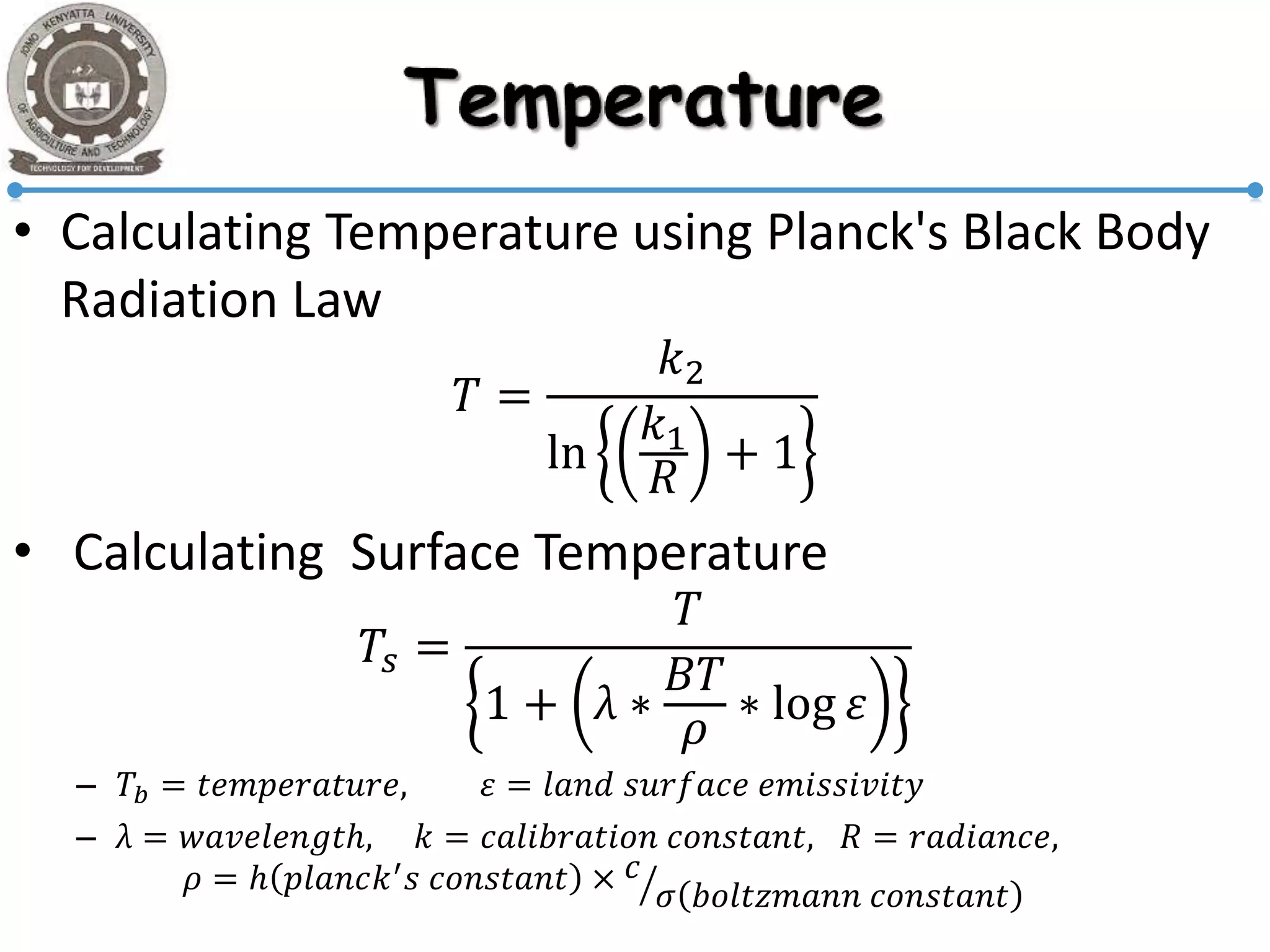
REMOTE SENSING
Thursday, 23 November 2017
Presenter:
J.Mwaura
ENC324-2981/2016
RS APPLICATIONS & SEMINAR
Black-0
White-255
Pixel
Grey values
DNs
• Radiometric resolution
–Sensor’s ability discriminate small differences in
the magnitude of radiation within the ground
area that corresponds to a
–The greater the bit depth (number of data bits
per pixel) of the images that a sensor records,
the
Sky
irradiance 𝐼𝑠
Sky
radiance 𝑅 𝑠
Path
radiance 𝑅 𝑝
T.O.A (𝐸 𝑜)
Pixel
irradiance
𝐼 𝑝
Radiant flux (𝜑)
From sun (𝑤𝑎𝑡𝑡𝑠)
Sensor
( 𝐸 𝑚
′
= 𝐸 𝑚 × 𝐺𝑎𝑖𝑛 +
(2) Surface element of reflectance (𝜌)
Incident
irradiance (𝐸𝑖)
Measured Radiance 𝐸 𝑚 = 𝑡(𝐸 𝑝 + 𝐼𝑠 + 𝐼 𝑝 + 𝑅 𝑝 + 𝑅 𝑠)
Outgoing
radiance(𝐸 𝑝)
Atmosphere
• Used to identify materials on earth surface
• …
• 𝑟𝑒𝑓𝑙𝑒𝑐𝑡𝑎𝑛𝑐𝑒 = 𝜌 =
𝐿
𝐸
=
𝑟𝑎𝑑𝑖𝑎𝑛𝑐𝑒
𝑖𝑟𝑟𝑎𝑑𝑖𝑎𝑛𝑐𝑒
• Convert D𝑁′
𝑠 to radiance using radiometric
calibration.
• Estimate incident irradiance (𝐸𝑖)
• Sun-elevation correction: 𝐸𝑖 = 𝐸 𝑇 ∗ 𝐶𝑜𝑠 𝜃
• 𝐸 𝑇 = 𝑖𝑟𝑟𝑎𝑑𝑖𝑎𝑛𝑐𝑒 𝑖𝑓 sun vertical at mean
Earth−Sun distance (𝑊/𝑚2)
• 𝐸𝑖 = 𝑎𝑐𝑡𝑢𝑎𝑙 𝑖𝑛𝑐𝑖𝑑𝑒𝑛𝑡 𝑒𝑛𝑒𝑟𝑔𝑦 (𝑊/𝑚2
)
• 𝜃 = 𝑠𝑜𝑙𝑎𝑟 𝑎𝑛𝑔𝑙𝑒 𝑓𝑟𝑜𝑚 𝑣𝑒𝑟𝑡𝑖𝑐𝑎𝑙
• (90 − 𝑠𝑜𝑙𝑎𝑟 𝑒𝑙𝑒𝑣𝑎𝑡𝑖𝑜𝑛 𝑎𝑛𝑔𝑙𝑒)
• Earth-Sun distance correction: 𝐸𝑖 = 𝐸 𝑇/𝑑2
• 𝑑 = 𝑒𝑎𝑟𝑡ℎ − 𝑠𝑢𝑛 𝑑𝑖𝑠𝑡𝑎𝑛𝑐𝑒
»(𝑖𝑛 𝑎𝑠𝑡𝑟𝑜𝑛𝑜𝑚𝑖𝑐𝑎𝑙 𝑢𝑛𝑖𝑡𝑠)
• Compute reflectance of a surface from image?
1. Outgoing radiance 𝐸 𝑝 = 𝐸 𝑚 − 𝑅 𝑝
2. Convert DN to radiance at sensor
𝐸 𝑜𝑢𝑡𝑝𝑢𝑡 = 𝐺 ∗ 𝐸𝑖𝑛𝑝𝑢𝑡 − 𝐵
𝐷𝑁 =
(𝐸 𝑜𝑢𝑡𝑝𝑢𝑡 + 𝐵)
𝐺
3. Estimate incident irradiance on the surface
𝐸𝑖 = 𝐸 𝑇 ∗ 𝐶𝑜𝑠 𝜃/𝑑2
4. Reflectance 𝜌 =
𝐸 𝑝
𝐸 𝑖
• Calculating Temperature using Planck's Black Body
Radiation Law
𝑇 =
𝑘2
ln
𝑘1
𝑅
+ 1
• Calculating Surface Temperature
𝑇𝑠 =
𝑇
1 + λ ∗
𝐵𝑇
𝜌
∗ log 𝜀
– 𝑇𝑏 = 𝑡𝑒𝑚𝑝𝑒𝑟𝑎𝑡𝑢𝑟𝑒, 𝜀 = 𝑙𝑎𝑛𝑑 𝑠𝑢𝑟𝑓𝑎𝑐𝑒 𝑒𝑚𝑖𝑠𝑠𝑖𝑣𝑖𝑡𝑦
– λ = 𝑤𝑎𝑣𝑒𝑙𝑒𝑛𝑔𝑡ℎ, 𝑘 = 𝑐𝑎𝑙𝑖𝑏𝑟𝑎𝑡𝑖𝑜𝑛 𝑐𝑜𝑛𝑠𝑡𝑎𝑛𝑡, 𝑅 = 𝑟𝑎𝑑𝑖𝑎𝑛𝑐𝑒,
𝜌 = ℎ 𝑝𝑙𝑎𝑛𝑐𝑘′ 𝑠 𝑐𝑜𝑛𝑠𝑡𝑎𝑛𝑡 × 𝑐
𝜎 𝑏𝑜𝑙𝑡𝑧𝑚𝑎𝑛𝑛 𝑐𝑜𝑛𝑠𝑡𝑎𝑛𝑡
• 𝐸 𝑝 𝜆 = 𝐸𝑖(𝜆) − 𝐸𝐴(𝜆) + 𝐸 𝑇(𝜆)
– 𝐸𝑖 = Incident energy
– 𝐸 𝑝 = 𝑅𝑒𝑓𝑙𝑒𝑐𝑡𝑒𝑑 𝑒𝑛𝑒𝑟𝑔𝑦
– 𝐸𝐴 = 𝐴𝑏𝑠𝑜𝑟𝑏𝑒𝑑
– 𝐸 𝑇 = 𝑇𝑟𝑎𝑛𝑠𝑚𝑖𝑡𝑡𝑒𝑑 𝑒𝑛𝑒𝑟𝑔𝑦
• 𝜌(𝜆) =
𝐸 𝑝(𝜆)
𝐸 𝑖(𝜆)
× 100
– 𝜌 𝜆 = 𝑠𝑝𝑒𝑐𝑡𝑟𝑎𝑙 𝑟𝑒𝑓𝑙𝑒𝑐𝑡𝑎𝑛𝑐𝑒 𝑜𝑓 𝑜𝑏𝑗𝑒𝑐𝑡
– 𝐴𝑏𝑠𝑜𝑟𝑝𝑡𝑎𝑛𝑐𝑒 = 𝐸 𝑎
𝐸 𝑖
× 100
– 𝑇𝑟𝑎𝑛𝑠𝑚𝑖𝑡𝑡𝑎𝑛𝑐𝑒 = 𝐸𝑡
𝐸 𝑖
× 100
• Brightness values for 8-bit system 0-255:
• 𝐷𝑁𝑠𝑡 = 255 × (𝐷𝑁 𝑖𝑛−𝐷𝑁 𝑚𝑖𝑛)
(𝐷𝑁 𝑚𝑎𝑥−𝐷𝑁 𝑚𝑖𝑛)
• 𝐷𝑁𝑠𝑡 = 255 𝑗=0
𝑘
(
𝑛 𝑗
𝑁
)
• 𝐷𝑁𝑠𝑡 = 𝑒𝑛ℎ𝑎𝑛𝑐𝑒𝑑 𝐷𝑁 𝑣𝑎𝑙𝑢𝑒
• 𝑛𝑗 = 𝑛𝑢𝑚𝑏𝑒𝑟 𝑜𝑓 𝑝𝑖𝑥𝑒𝑙𝑠 ℎ𝑎𝑣𝑖𝑛𝑔 𝐷𝑁 𝑣𝑎𝑙𝑢𝑒𝑠 𝑖𝑛 𝑡ℎ𝑒
𝑗 𝑡ℎ 𝑟𝑎𝑛𝑔𝑒, 𝑖𝑛 𝑡ℎ𝑒 𝑖𝑛𝑝𝑢𝑡 𝑖𝑚𝑎𝑔𝑒
• 𝑘 = 𝑚𝑎𝑥. 𝑛𝑢𝑚𝑏𝑒𝑟 𝑜𝑓 𝐷𝑁 𝑟𝑎𝑛𝑔𝑒𝑠 𝑖𝑛 𝑖𝑛𝑝𝑢𝑡 𝑖𝑚𝑎𝑔𝑒
• 𝑁 = 𝑇𝑜𝑡𝑎𝑙 𝑛𝑢𝑚𝑏𝑒𝑟 𝑜𝑓 𝑝𝑖𝑥𝑒𝑙𝑠 𝑖𝑛 𝑖𝑛𝑝𝑢𝑡 𝑖𝑚𝑎𝑔𝑒
Thanks…
>> Part 2
Applicability of the Mix–Unmix Classifier in
percentage tree and soil cover mapping
Thursday, 23 November 2017
Author:
T. NGIGI et.al
RS APPLICATIONS & SEMINAR
Problem
• The under-determination in linear spectral
unmixing
Percentage tree
cover mapping
• Data
–composite MODIS data {bands 1–7}
–excluded band 5
• stripping
–resampled {bands 1,2,3,4 & 6,7} from 500
m to 1 km.
• reduce the volume
Selection of band to
unmix
}
MODIS first 7
bands: 500m
MODIS 6 bands:
1km
Skewness
image
Scatter plot
Interactive on-screen
comparison
Vegetation skewness
image
1. Most pure
equatorial
rainforest
skewness
2. Most impure
equatorial
rainforest
skewness range
Skewness
image
Mix-unmix
classification
% tree
mapping
Omit band 5
& resample
Transformations:
PCs, MNFs,
NDVI, Compute
Parameters
Analysis
• The redder the skewness
image, the denser the
equatorial forest
• DN ranges of 1–10:
– Most impure forest
• DN ranges of 80–131:
– Most pure forest
• All DNs in range 1–131 in
skewness image were
unmixed, as above classes
by the Mix–Unmix
Classifier
That’s it
Thanks…

Remote Sensing

  • 1.
    REMOTE SENSING Thursday, 23November 2017 Presenter: J.Mwaura ENC324-2981/2016 RS APPLICATIONS & SEMINAR
  • 2.
  • 3.
    • Radiometric resolution –Sensor’sability discriminate small differences in the magnitude of radiation within the ground area that corresponds to a –The greater the bit depth (number of data bits per pixel) of the images that a sensor records, the
  • 4.
    Sky irradiance 𝐼𝑠 Sky radiance 𝑅𝑠 Path radiance 𝑅 𝑝 T.O.A (𝐸 𝑜) Pixel irradiance 𝐼 𝑝 Radiant flux (𝜑) From sun (𝑤𝑎𝑡𝑡𝑠) Sensor ( 𝐸 𝑚 ′ = 𝐸 𝑚 × 𝐺𝑎𝑖𝑛 + (2) Surface element of reflectance (𝜌) Incident irradiance (𝐸𝑖) Measured Radiance 𝐸 𝑚 = 𝑡(𝐸 𝑝 + 𝐼𝑠 + 𝐼 𝑝 + 𝑅 𝑝 + 𝑅 𝑠) Outgoing radiance(𝐸 𝑝) Atmosphere
  • 5.
    • Used toidentify materials on earth surface • … • 𝑟𝑒𝑓𝑙𝑒𝑐𝑡𝑎𝑛𝑐𝑒 = 𝜌 = 𝐿 𝐸 = 𝑟𝑎𝑑𝑖𝑎𝑛𝑐𝑒 𝑖𝑟𝑟𝑎𝑑𝑖𝑎𝑛𝑐𝑒
  • 6.
    • Convert D𝑁′ 𝑠to radiance using radiometric calibration. • Estimate incident irradiance (𝐸𝑖)
  • 7.
    • Sun-elevation correction:𝐸𝑖 = 𝐸 𝑇 ∗ 𝐶𝑜𝑠 𝜃 • 𝐸 𝑇 = 𝑖𝑟𝑟𝑎𝑑𝑖𝑎𝑛𝑐𝑒 𝑖𝑓 sun vertical at mean Earth−Sun distance (𝑊/𝑚2) • 𝐸𝑖 = 𝑎𝑐𝑡𝑢𝑎𝑙 𝑖𝑛𝑐𝑖𝑑𝑒𝑛𝑡 𝑒𝑛𝑒𝑟𝑔𝑦 (𝑊/𝑚2 ) • 𝜃 = 𝑠𝑜𝑙𝑎𝑟 𝑎𝑛𝑔𝑙𝑒 𝑓𝑟𝑜𝑚 𝑣𝑒𝑟𝑡𝑖𝑐𝑎𝑙 • (90 − 𝑠𝑜𝑙𝑎𝑟 𝑒𝑙𝑒𝑣𝑎𝑡𝑖𝑜𝑛 𝑎𝑛𝑔𝑙𝑒)
  • 8.
    • Earth-Sun distancecorrection: 𝐸𝑖 = 𝐸 𝑇/𝑑2 • 𝑑 = 𝑒𝑎𝑟𝑡ℎ − 𝑠𝑢𝑛 𝑑𝑖𝑠𝑡𝑎𝑛𝑐𝑒 »(𝑖𝑛 𝑎𝑠𝑡𝑟𝑜𝑛𝑜𝑚𝑖𝑐𝑎𝑙 𝑢𝑛𝑖𝑡𝑠)
  • 9.
    • Compute reflectanceof a surface from image? 1. Outgoing radiance 𝐸 𝑝 = 𝐸 𝑚 − 𝑅 𝑝 2. Convert DN to radiance at sensor 𝐸 𝑜𝑢𝑡𝑝𝑢𝑡 = 𝐺 ∗ 𝐸𝑖𝑛𝑝𝑢𝑡 − 𝐵 𝐷𝑁 = (𝐸 𝑜𝑢𝑡𝑝𝑢𝑡 + 𝐵) 𝐺 3. Estimate incident irradiance on the surface 𝐸𝑖 = 𝐸 𝑇 ∗ 𝐶𝑜𝑠 𝜃/𝑑2 4. Reflectance 𝜌 = 𝐸 𝑝 𝐸 𝑖
  • 10.
    • Calculating Temperatureusing Planck's Black Body Radiation Law 𝑇 = 𝑘2 ln 𝑘1 𝑅 + 1 • Calculating Surface Temperature 𝑇𝑠 = 𝑇 1 + λ ∗ 𝐵𝑇 𝜌 ∗ log 𝜀 – 𝑇𝑏 = 𝑡𝑒𝑚𝑝𝑒𝑟𝑎𝑡𝑢𝑟𝑒, 𝜀 = 𝑙𝑎𝑛𝑑 𝑠𝑢𝑟𝑓𝑎𝑐𝑒 𝑒𝑚𝑖𝑠𝑠𝑖𝑣𝑖𝑡𝑦 – λ = 𝑤𝑎𝑣𝑒𝑙𝑒𝑛𝑔𝑡ℎ, 𝑘 = 𝑐𝑎𝑙𝑖𝑏𝑟𝑎𝑡𝑖𝑜𝑛 𝑐𝑜𝑛𝑠𝑡𝑎𝑛𝑡, 𝑅 = 𝑟𝑎𝑑𝑖𝑎𝑛𝑐𝑒, 𝜌 = ℎ 𝑝𝑙𝑎𝑛𝑐𝑘′ 𝑠 𝑐𝑜𝑛𝑠𝑡𝑎𝑛𝑡 × 𝑐 𝜎 𝑏𝑜𝑙𝑡𝑧𝑚𝑎𝑛𝑛 𝑐𝑜𝑛𝑠𝑡𝑎𝑛𝑡
  • 11.
    • 𝐸 𝑝𝜆 = 𝐸𝑖(𝜆) − 𝐸𝐴(𝜆) + 𝐸 𝑇(𝜆) – 𝐸𝑖 = Incident energy – 𝐸 𝑝 = 𝑅𝑒𝑓𝑙𝑒𝑐𝑡𝑒𝑑 𝑒𝑛𝑒𝑟𝑔𝑦 – 𝐸𝐴 = 𝐴𝑏𝑠𝑜𝑟𝑏𝑒𝑑 – 𝐸 𝑇 = 𝑇𝑟𝑎𝑛𝑠𝑚𝑖𝑡𝑡𝑒𝑑 𝑒𝑛𝑒𝑟𝑔𝑦 • 𝜌(𝜆) = 𝐸 𝑝(𝜆) 𝐸 𝑖(𝜆) × 100 – 𝜌 𝜆 = 𝑠𝑝𝑒𝑐𝑡𝑟𝑎𝑙 𝑟𝑒𝑓𝑙𝑒𝑐𝑡𝑎𝑛𝑐𝑒 𝑜𝑓 𝑜𝑏𝑗𝑒𝑐𝑡 – 𝐴𝑏𝑠𝑜𝑟𝑝𝑡𝑎𝑛𝑐𝑒 = 𝐸 𝑎 𝐸 𝑖 × 100 – 𝑇𝑟𝑎𝑛𝑠𝑚𝑖𝑡𝑡𝑎𝑛𝑐𝑒 = 𝐸𝑡 𝐸 𝑖 × 100
  • 12.
    • Brightness valuesfor 8-bit system 0-255: • 𝐷𝑁𝑠𝑡 = 255 × (𝐷𝑁 𝑖𝑛−𝐷𝑁 𝑚𝑖𝑛) (𝐷𝑁 𝑚𝑎𝑥−𝐷𝑁 𝑚𝑖𝑛) • 𝐷𝑁𝑠𝑡 = 255 𝑗=0 𝑘 ( 𝑛 𝑗 𝑁 ) • 𝐷𝑁𝑠𝑡 = 𝑒𝑛ℎ𝑎𝑛𝑐𝑒𝑑 𝐷𝑁 𝑣𝑎𝑙𝑢𝑒 • 𝑛𝑗 = 𝑛𝑢𝑚𝑏𝑒𝑟 𝑜𝑓 𝑝𝑖𝑥𝑒𝑙𝑠 ℎ𝑎𝑣𝑖𝑛𝑔 𝐷𝑁 𝑣𝑎𝑙𝑢𝑒𝑠 𝑖𝑛 𝑡ℎ𝑒 𝑗 𝑡ℎ 𝑟𝑎𝑛𝑔𝑒, 𝑖𝑛 𝑡ℎ𝑒 𝑖𝑛𝑝𝑢𝑡 𝑖𝑚𝑎𝑔𝑒 • 𝑘 = 𝑚𝑎𝑥. 𝑛𝑢𝑚𝑏𝑒𝑟 𝑜𝑓 𝐷𝑁 𝑟𝑎𝑛𝑔𝑒𝑠 𝑖𝑛 𝑖𝑛𝑝𝑢𝑡 𝑖𝑚𝑎𝑔𝑒 • 𝑁 = 𝑇𝑜𝑡𝑎𝑙 𝑛𝑢𝑚𝑏𝑒𝑟 𝑜𝑓 𝑝𝑖𝑥𝑒𝑙𝑠 𝑖𝑛 𝑖𝑛𝑝𝑢𝑡 𝑖𝑚𝑎𝑔𝑒
  • 13.
  • 14.
    Applicability of theMix–Unmix Classifier in percentage tree and soil cover mapping Thursday, 23 November 2017 Author: T. NGIGI et.al RS APPLICATIONS & SEMINAR
  • 15.
    Problem • The under-determinationin linear spectral unmixing
  • 16.
    Percentage tree cover mapping •Data –composite MODIS data {bands 1–7} –excluded band 5 • stripping –resampled {bands 1,2,3,4 & 6,7} from 500 m to 1 km. • reduce the volume
  • 17.
    Selection of bandto unmix } MODIS first 7 bands: 500m MODIS 6 bands: 1km Skewness image Scatter plot Interactive on-screen comparison Vegetation skewness image 1. Most pure equatorial rainforest skewness 2. Most impure equatorial rainforest skewness range Skewness image Mix-unmix classification % tree mapping Omit band 5 & resample Transformations: PCs, MNFs, NDVI, Compute Parameters
  • 18.
    Analysis • The redderthe skewness image, the denser the equatorial forest • DN ranges of 1–10: – Most impure forest • DN ranges of 80–131: – Most pure forest • All DNs in range 1–131 in skewness image were unmixed, as above classes by the Mix–Unmix Classifier
  • 19.