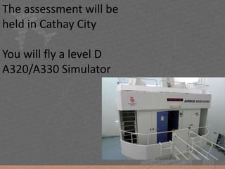
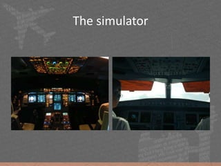
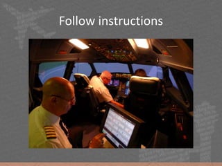
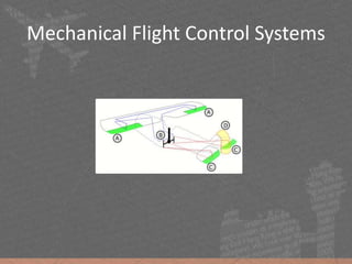
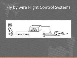
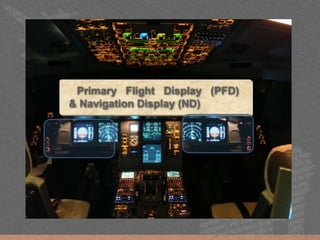
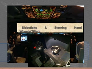
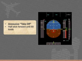
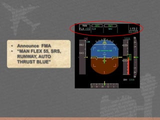
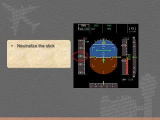
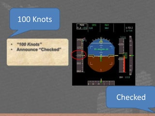
To understand the requirements of the CDACP simulator assessment
To have a basic idea of the Airbus flight control system
To practise the assessment via personal computer flight simulator
Dragonair Certificate Program A320 Screening FlightYuuji
This document provides instructions for a flight simulator demonstration of flying an Airbus A320. It begins with an introduction and overview of the simulator activity. It then provides a detailed guide to the Airbus cockpit instrumentation, including explanations of the primary flight display, navigation display, flight management computer, autopilot, and fly-by-wire controls. The document concludes with guidance on performing an ILS approach and landing simulation in the Airbus A320 simulator.
Dragonair Certificate Program A330 Screening FlightYuuji
The document discusses the electronic flight instrument system (EFIS) displays in aircraft. It provides the following key points:
- The EFIS displays include primary flight displays (PFD) that show flight parameters and navigation displays (ND) that show navigation data.
- The PFD displays critical flight information like attitude, airspeed, altitude, heading in a classic "T" configuration for the pilot.
- The displays present information to the pilots to safely and efficiently operate the aircraft.
Dragonair Certificate Program Screening Flight Yuuji
This document provides an overview of an Airbus A320 flight simulator session. It discusses preparing participants by explaining the key flight instruments like the electronic flight instrument system (EFIS) displays. It then guides participants through a simulated taxi, takeoff, and climb in the simulator, explaining instrument readings and controls. The goal is to familiarize participants with flying the A320 before they do a supervised session in the simulator.
This document discusses various types of radio navigation and the electronic flight instrument system displays used for instrument approaches. It focuses on non-directional beacons, VOR navigation, the instrument landing system including localizer and glideslope, and airspeed indications shown on the primary flight display during an ILS approach involving multiple flap configurations and speed reductions. Sample electronic flight display screenshots are included to illustrate airspeed, altitude, navigation, and approach guidance information.
The document provides instructions for a simulator practice session on an Airbus A330. It details the simulator procedures, including starting the engines, taking off, climbing to cruise altitude, and performing an approach and landing. Key steps covered are following the flight director, monitoring speeds during flap configuration changes, and using primary flight displays and navigation displays to read flight parameters and navigate.
The document provides information about a simulator flight assessment for an Airbus A320/A330. It includes an overview of the simulator and key aircraft systems that will be demonstrated, such as the primary flight display, navigation display, flight controls, and flight modes. The summary will cover the key steps of the assessment, including takeoff, climb, approach and landing procedures while following the flight director.
CARE is a charity that provides aviation education courses in Hong Kong. It has partnered with youth organizations since 2009 and established a connection with a UK flight school in 2015. Students who complete CARE's program can receive recommendations to participate in the flight school's private pilot program. The document then describes the electronic flight displays on Airbus aircraft, including the primary flight display, navigation display, and their various modes and symbology relating to flight parameters, navigation, weather radar, and the flight management system.
This document provides information about various aircraft instruments including:
- The airspeed indicator which uses ram air from the pitot tube and static air, and displays airspeeds like Vso and Vfe. Blockages of the pitot tube or static vent can cause errors.
- The altimeter which uses only static air input and displays various altitudes like indicated, pressure, and density altitude. Not updating the altimeter setting can cause errors.
- Gyroscopic instruments like the attitude indicator and heading indicator which function based on the principles of rigidity in space and precession.
- The turn coordinator and inclinometer which indicate aircraft bank and slip/skid.
- The magnetic compass
Two radio altimeters are installed in the A320 to accurately measure the aircraft's height above ground. They automatically activate when power is applied and provide continuous measurements from lift-off to touchdown. Radio altitude is displayed on the pilot's displays below 2,500 feet and provides input to several aircraft systems. Visual and audio cues are provided to the pilots as the aircraft descends to indicate proximity to the ground.
This document provides an overview of the course modules for an aircraft systems course. It covers 14 modules from May to July, focusing on electronic instrument systems and digital techniques. It describes the primary flight instruments, flight control surfaces, aircraft axes, navigation methods including ADF, VOR, GPS, and approaches including visual, ILS, and autopilot functions. It also outlines the cockpit layouts of the Cessna and Airbus A320, comparing traditional instruments to glass cockpit displays.
This document summarizes various aircraft instrumentation systems including:
- The pitot-static system which includes the altimeter, vertical speed indicator, and airspeed indicator.
- Gyroscopic instruments like the turn coordinator, artificial horizon, and heading indicator.
- Other instruments like the magnetic compass and outside air temperature gauge.
It provides details on how each instrument works and key terms related to altitude, airspeed, and gyroscopic principles.
This document discusses flight instruments that utilize the pitot-static system, including the airspeed indicator, altimeter, and vertical speed indicator. It explains that the pitot tube measures total pressure, while the static ports measure ambient pressure, and the difference between these pressures drives the readings on the instruments. It also discusses factors like non-standard temperature and pressure that can introduce errors, and the importance of setting the correct altimeter setting to compensate for these errors and obtain an accurate altitude reading.
This document discusses aircraft flight instruments. It begins by asking what flight instruments are and why they are needed, particularly in poor visibility conditions. It then provides an overview of the typical instrument layout, known as the "six pack", and proceeds to describe each individual instrument - including the altimeter, attitude indicator, turn coordinator, heading indicator, vertical speed indicator, and airspeed indicator. It explains that some instruments rely on pitot-static systems while others use gyroscopes. In conclusion, it emphasizes the importance of knowing how to read these instruments well in order to fly an aircraft.
The document provides an overview of the various instruments and displays pilots interact with when flying a fighter jet. It describes instruments that indicate speed like the airspeed indicator and machmeter. It also covers altitude instruments like the altimeter and radar altimeter. Other instruments discussed include the artificial horizon, vertical airspeed indicator, compass, gyrocompass, head-up display, and helmet-mounted display. The document also summarizes controls like the throttle and stick, as well as multifunction displays and flight data recorders.
This document provides an introduction to navigation methods for aircraft, including visual flight rules (VFR), instrument flight rules (IFR), and various types of radio navigation equipment. It focuses on radio navigation methods like non-directional beacons (NDB), VHF omnidirectional range (VOR), distance measuring equipment (DME), and instrument landing system (ILS). Key aspects like tracking VOR courses, ILS localizers and glideslopes, and ILS categories are explained. The goal is to prepare pilots flying Boeing 737-800 aircraft to use radio and area navigation methods.
The document provides an overview of basic flight instruments and modern glass cockpit instruments. It discusses the airspeed indicator, attitude indicator, altimeter, turn indicator, heading indicator, vertical speed indicator as the basic flight instruments. For modern instruments, it describes the primary flight display, multi-function display, and electronic centralized aircraft monitoring display that make up an electronic flight instrument system or glass cockpit.
This document outlines key differences in phraseology used in air traffic control communications between the International Civil Aviation Organization (ICAO) and the United States Federal Aviation Administration (FAA). It discusses differences in terminology for air traffic control units, procedures for clearances, wake turbulence separation, use of headings versus tracks, procedures following loss of radio communication, holding patterns, and approach procedures. The document is intended to help pilots learn and understand differences that could impact safety and procedures when flying internationally.
The document discusses the Instrument Landing System (ILS), which provides aircraft with horizontal and vertical guidance just before and during landing. It has key components including localizer antennas that guide left/right movement and glide slope antennas that guide up/down movement. Marker beacons help pilots check aircraft position at certain distances from the runway. ILS allows landings in low visibility conditions down to Category III, with no visibility limitations. It transmits radio signals received by aircraft to indicate proper alignment on the landing path.
The document discusses the standard six primary flight instruments including the airspeed indicator, attitude indicator, altimeter, vertical speed indicator, turn coordinator, and heading indicator. It explains what each instrument measures, how it works, and how to read it. For example, it states that the airspeed indicator uses pitot tubes and static ports to measure speed through the air, while the altimeter measures air pressure to determine altitude. It also provides some sample instrument readings and poses quiz questions about using combined instruments to replace one that has failed.
This document provides an overview of the autopilot and flight management systems on an aircraft. It describes the key components like the flight management and guidance system (FMGS), flight management and guidance computers (FMGCs), flight control unit (FCU), and autopilot. It explains how the autopilot, flight directors, and auto thrust systems work together to control the aircraft and achieve different flight modes. The flight mode annunciations (FMAs) indicate the engaged, armed and status of the auto flight systems.
Pitot Static System is hugely used in aviation sector. Even almost all modern aircrafts use this ancient technology to calculate their airspeed, altitude, and vertical speed.
The system is briefly but exquisitely presented in this slide.
Instrumental Landing System - ILS - Airport EngineeringTheerumalai Ga
A short note on the Instrumental Landing system used for flight landing in Airport Engineering. Worked for an assignment. Hope it'll help you for a read to know about ILS
The document provides an overview of the Instrument Landing System (ILS) and Air Traffic Control (ATC). ILS is a precision instrument approach system that provides horizontal and vertical guidance to aircraft approaching and landing on a runway. It uses separate antenna arrays to transmit left-right and up-down signals to guide the pilot. ATC manages air traffic to prevent collisions and maximize efficiency. Modernization efforts aim to upgrade outdated radar/radio systems and address issues like congestion through new GPS and satellite technologies. While ILS and ATC play key roles in safety and efficiency, challenges remain in fully implementing new solutions.
The document discusses air traffic control and services. It aims to prevent collisions between aircraft during flight and on the ground through separating aircraft laterally and longitudinally based on distance and time. It describes control areas like aerodromes and traffic zones. It also discusses flight level assignment, area navigation systems, routes and waypoints to guide aircraft along planned paths.
Media Object File Flt Ops Ops Env Seq02syed viquar
This document provides guidance on enhancing terrain awareness during flight operations. It discusses factors that affect terrain awareness, such as aircraft equipment, airport environment, navigation charts, and human factors. Recommendations are provided for cockpit preparation, standard instrument departures and arrivals, descent management, approach briefings, and go-around procedures. Maintaining situational awareness of terrain and obstacles is important for safety, especially in mountainous or hilly areas.
The document provides instructions for performing a left-hand traffic pattern at an airport, including briefings for each leg of the pattern. It discusses the departure, crosswind, downwind, base, and final legs, as well as the approach and landing. It also defines some aviation terminology and reviews keyboard commands for aircraft control.
The cockpit of an airplane contains various flight controls and instruments that pilots use to navigate the aircraft. The yoke or stick controls the ailerons and elevator to turn the plane and change altitude. Rudder pedals help control turns. Instruments such as the airspeed indicator, altimeter, and heading indicator provide key flight data. Pilots also use radios, transponders and GPS for navigation and communication with air traffic control.
A presentation that guides the student through the forces acting on an aircraft, and how to fly a circuit at a typical airfield. This includes aircraft instrumentation and radio use. THIS PRESENTATION IS FOR INTEREST AND SIMULATED FLIGHT ONLY, AS PROPER FLIGHT INSTRUCTION SHOULD BE TAKEN FOR ACTUAL FLIGHT
In this presentation, you will learn in detail how the instruments inside the plane work with the differences in air pressure outside the plane. You will also learn how to manipulate
The document provides an overview of the basic flight controls and instruments found in the cockpit of an airplane. It describes the yoke or stick used to control the ailerons and elevators, as well as the rudder pedals. Key flight instruments like the airspeed indicator, attitude indicator, altimeter, turn coordinator, heading indicator, and vertical speed indicator are also outlined. The document concludes with a brief discussion of communication radios, transponders, and GPS systems used by pilots.
The autopilot flight director system (AFDS) consists of two flight control computers and a mode control panel. The AFDS and autothrottle are controlled automatically by the flight management computer to fly the optimized flight path. The mode control panel is used to select AFDS and autothrottle modes, with engaged modes annunciated on the flight mode annunciator. The flight director displays command guidance for the pilot when engaged but does not provide flare guidance for landing.
This document provides information about the Computerized Pilot Selection System (CPSS) and Pilot Aptitude Battery Test (PABT) used to select pilots for the Indian armed forces. It describes the two parts of the CPSS, which tests psychomotor skills and cognitive abilities through multiple choice questions and machine tests. It then outlines the three tests that make up the PABT: the Instrument Battery Test, Sensory Motor Apparatus Test, and Control Velocity Test. These tests evaluate a candidate's ability to read instruments, respond to stimuli, and perform coordinated tasks. The goal is to assess qualities like mental alertness, presence of mind, self-confidence, and nerve control for pilots.
For Video Lecture of this presentation: https://youtu.be/8sMbl6pJpd0
The topics covered in this session are, Primary flight instruments: Altimeter, ASI (Airspeed Indicator ), VSI (vertical speed indicator) , Turn-bank indicator. The session is categorized into two portions namely, pitot-static system based and gyroscopic instrument based.
Attention! "Gate Aerospace Engineering aspirants", A virtual guide for gate aerospace engineering is provided in "Age of Aerospace" blog for helping you meticulously prepare for gate examination. Respective notes of individual subjects are provided as 'Embedded Google Docs' which are frequently updated. This comprehensive guide is intended to efficiently serve as an extensive collection of online resources for "GATE Aerospace Engineering" which can be accessed free of cost. Use the following link to access the study material
https://ageofaerospace.blogspot.com/p/gate-aerospace.html
This document provides guidance and procedures for operating the A-4E-C aircraft in DCS World, including:
1. An overview of the aircraft cockpit layout and startup procedure.
2. Notes and checklists for takeoff, landing, and shutdown.
3. Information on the automatic flight control system (AFCS) and its operating modes.
4. Procedures for carrier operations including catapult launches and arrested landings.
5. Descriptions of the aircraft's navigation equipment and instructions for TACAN navigation.
The document discusses the flight control systems of the Boeing 747-400, including descriptions of:
1) The aileron, spoiler, elevator, rudder, and flap control systems. It describes the components and functions of each system.
2) The modes of operation for the flap control system including primary, secondary, and alternate modes. It provides details on flap sequencing and position indication.
3) Indications that may appear related to problems with the flight control systems like disagreements between sensors or failures in certain components.
Introduction to aircraft communicating systemRosy Satwe
1. Airband refers to VHF radio frequencies between 108-137 MHz that are allocated for civil aviation radio communications.
2. Within the airband, different sections are used for radio navigation aids and air traffic control, with channels spaced initially at 200 kHz, then 100 kHz, 50 kHz, 25 kHz and currently some channels spaced at 8.33 kHz.
3. The airband allows pilots and air traffic control to communicate regarding flight paths, clearances, emergencies and instructions to ensure safe air travel.
This document provides a description and overview of the autopilot and yaw damper system for a B727-200 aircraft. It describes the major components, including the Sperry SP-50 MB V Automatic Flight Control System, which provides three-axis flight stabilization and automatic approach capability. It details the functions of the yaw, roll, and pitch axes, and describes the components that control and provide inputs to each axis, such as rudder power units, aileron servos, elevator power units, and sensors. The document also notes the locations of components throughout the aircraft.
AIRCRAFT WEIGHT AND BALANCE BASIC FOR LOAD CONTROLjasmine jacob
The document discusses aircraft weight and balance requirements. It covers key topics such as:
1) Compliance with weight and balance limits is critical for flight safety, as exceeding maximum weight limits can compromise structural integrity and affect aircraft performance. Operating with the center of gravity outside approved limits can also cause control difficulties.
2) Proper load planning, distribution, and securing of cargo and baggage is required. Various aircraft compartments and structural loading limitations must be followed.
3) Dangerous goods and special items require special documentation and handling procedures. Records of weight and balance calculations must be retained for regulatory compliance.
On Landings Part I FAA P-8740-48. This pamphlet includes a complimentary video: https://www.youtube.com/watch?v=5ThKEI8ibwM&list=PL1EvWLSzQrXO71Dm-QN_9repsMo7k1Zeg
This document discusses approach and landing performance requirements. It covers topics like approach definition, maximum and minimum speeds, landing weight limitations, climb requirements, landing distances, and factors affecting landing distance. Specifically, it defines speeds like VREF (reference landing approach speed) and VAPP (actual landing speed). It also discusses requirements for landing and approach climb gradients, and how to calculate landing distance required versus landing distance available on the runway.
This document provides guidance for powering on and preparing a Boeing 737NG aircraft from a cold and dark state for flight simulation purposes only. It outlines steps to power on systems, complete checklists, and configure the aircraft, including MCDU/FMC setup, cabin preparation, overhead and main panel scans, and engine start procedures. The document emphasizes this is for simulation only and not to be used for actual flight. It provides detailed guidance on configuring and checking multiple aircraft systems from a cold start condition through taxi and takeoff.
This document provides guidance for Airbus A330 pilots on approach briefings and flows. Key points include:
1) The Weather-Automation-Report-Descent framework for approach briefings and flows. Automation flows include programming the MCDU and checking navigation accuracy for ILS or RNAV approaches.
2) Callouts for various phases of flight from takeoff to flap retraction. Callouts include speeds, configurations, and automation selections.
3) Callouts and procedures for a loss of thrust after V1, a rejected takeoff, and ILS CAT I, II, and III approaches. Briefings and callouts focus on checklist flows, altitudes, speeds, and automation.
Aircraft Auto Pilot Roll Control SystemSuchit Moon
This document discusses the components and functions of an aircraft roll control system for autopilot. It describes the primary flight control surfaces - ailerons, rudder, and elevators - and their purposes. It then explains the components that make up the roll control system, including the controller gain, aileron actuator, aircraft dynamics model, and gyro. The system uses these components to automatically control and maintain the aircraft's roll angle based on input from the gyro. Autopilot systems provide advantages such as reducing pilot workload and fatigue during flight.
Mission analysis of Frankie Kam's Tornado videoFrankie Kam
1) The document analyzes a Tornado flight simulator mission recording to learn lessons from both the takeoff and landing.
2) During takeoff, the pilot exceeded the flap retraction speed limit, causing a warning. The analysis discusses proper procedures and limit speeds.
3) On approach, the pilot flew too fast between waypoints, causing the autopilot to disconnect due to an excessively tight turn radius. The analysis examines turn radius effects.
Similar to Cathay Dragon Certificate Programme 2018 A320/A330 Simulator Flight (20)
This slide is special for master students (MIBS & MIFB) in UUM. Also useful for readers who are interested in the topic of contemporary Islamic banking.
ISO/IEC 27001, ISO/IEC 42001, and GDPR: Best Practices for Implementation and...PECB
Denis is a dynamic and results-driven Chief Information Officer (CIO) with a distinguished career spanning information systems analysis and technical project management. With a proven track record of spearheading the design and delivery of cutting-edge Information Management solutions, he has consistently elevated business operations, streamlined reporting functions, and maximized process efficiency.
Certified as an ISO/IEC 27001: Information Security Management Systems (ISMS) Lead Implementer, Data Protection Officer, and Cyber Risks Analyst, Denis brings a heightened focus on data security, privacy, and cyber resilience to every endeavor.
His expertise extends across a diverse spectrum of reporting, database, and web development applications, underpinned by an exceptional grasp of data storage and virtualization technologies. His proficiency in application testing, database administration, and data cleansing ensures seamless execution of complex projects.
What sets Denis apart is his comprehensive understanding of Business and Systems Analysis technologies, honed through involvement in all phases of the Software Development Lifecycle (SDLC). From meticulous requirements gathering to precise analysis, innovative design, rigorous development, thorough testing, and successful implementation, he has consistently delivered exceptional results.
Throughout his career, he has taken on multifaceted roles, from leading technical project management teams to owning solutions that drive operational excellence. His conscientious and proactive approach is unwavering, whether he is working independently or collaboratively within a team. His ability to connect with colleagues on a personal level underscores his commitment to fostering a harmonious and productive workplace environment.
Date: May 29, 2024
Tags: Information Security, ISO/IEC 27001, ISO/IEC 42001, Artificial Intelligence, GDPR
-------------------------------------------------------------------------------
Find out more about ISO training and certification services
Training: ISO/IEC 27001 Information Security Management System - EN | PECB
ISO/IEC 42001 Artificial Intelligence Management System - EN | PECB
General Data Protection Regulation (GDPR) - Training Courses - EN | PECB
Webinars: https://pecb.com/webinars
Article: https://pecb.com/article
-------------------------------------------------------------------------------
For more information about PECB:
Website: https://pecb.com/
LinkedIn: https://www.linkedin.com/company/pecb/
Facebook: https://www.facebook.com/PECBInternational/
Slideshare: http://www.slideshare.net/PECBCERTIFICATION
বাংলাদেশের অর্থনৈতিক সমীক্ষা ২০২৪ [Bangladesh Economic Review 2024 Bangla.pdf] কম্পিউটার , ট্যাব ও স্মার্ট ফোন ভার্সন সহ সম্পূর্ণ বাংলা ই-বুক বা pdf বই " সুচিপত্র ...বুকমার্ক মেনু 🔖 ও হাইপার লিংক মেনু 📝👆 যুক্ত ..
আমাদের সবার জন্য খুব খুব গুরুত্বপূর্ণ একটি বই ..বিসিএস, ব্যাংক, ইউনিভার্সিটি ভর্তি ও যে কোন প্রতিযোগিতা মূলক পরীক্ষার জন্য এর খুব ইম্পরট্যান্ট একটি বিষয় ...তাছাড়া বাংলাদেশের সাম্প্রতিক যে কোন ডাটা বা তথ্য এই বইতে পাবেন ...
তাই একজন নাগরিক হিসাবে এই তথ্য গুলো আপনার জানা প্রয়োজন ...।
বিসিএস ও ব্যাংক এর লিখিত পরীক্ষা ...+এছাড়া মাধ্যমিক ও উচ্চমাধ্যমিকের স্টুডেন্টদের জন্য অনেক কাজে আসবে ...
How to Build a Module in Odoo 17 Using the Scaffold MethodCeline George
Odoo provides an option for creating a module by using a single line command. By using this command the user can make a whole structure of a module. It is very easy for a beginner to make a module. There is no need to make each file manually. This slide will show how to create a module using the scaffold method.
This presentation was provided by Steph Pollock of The American Psychological Association’s Journals Program, and Damita Snow, of The American Society of Civil Engineers (ASCE), for the initial session of NISO's 2024 Training Series "DEIA in the Scholarly Landscape." Session One: 'Setting Expectations: a DEIA Primer,' was held June 6, 2024.
it describes the bony anatomy including the femoral head , acetabulum, labrum . also discusses the capsule , ligaments . muscle that act on the hip joint and the range of motion are outlined. factors affecting hip joint stability and weight transmission through the joint are summarized.
A Strategic Approach: GenAI in EducationPeter Windle
Artificial Intelligence (AI) technologies such as Generative AI, Image Generators and Large Language Models have had a dramatic impact on teaching, learning and assessment over the past 18 months. The most immediate threat AI posed was to Academic Integrity with Higher Education Institutes (HEIs) focusing their efforts on combating the use of GenAI in assessment. Guidelines were developed for staff and students, policies put in place too. Innovative educators have forged paths in the use of Generative AI for teaching, learning and assessments leading to pockets of transformation springing up across HEIs, often with little or no top-down guidance, support or direction.
This Gasta posits a strategic approach to integrating AI into HEIs to prepare staff, students and the curriculum for an evolving world and workplace. We will highlight the advantages of working with these technologies beyond the realm of teaching, learning and assessment by considering prompt engineering skills, industry impact, curriculum changes, and the need for staff upskilling. In contrast, not engaging strategically with Generative AI poses risks, including falling behind peers, missed opportunities and failing to ensure our graduates remain employable. The rapid evolution of AI technologies necessitates a proactive and strategic approach if we are to remain relevant.
1. Airbus A320/A330 simulator flight
Preparation and lecture for DACP screening
Yuuji Izumo Jacklyn Wu Gilbert Lee
CARE - Charity for Aviation - Recreation and Education
2. Objective
• To understand the requirements of the DACP
simulator assessment
• To have a basic idea of the Airbus flight control
system
• To practise the assessment via personal
computer flight simulator
3. What we are not going to do
• To teach Standard Operating Procedures of
any company
• To teach how to fly an airliner
4. What we are going to do
• Read and interpret the instrument
• Watch demonstration
• Learn how to handle the aircraft
5. The assessment will be
held in Cathay City
You will fly a level D
A320/A330 Simulator
17. Flight parameters are displayed on
Primary Flight Displays (PFD)
while navigation data is displayed on
Navigation Displays(ND)
PFD1 PFD2ND1 ND2
18. ND has several modes.
In ARC mode,
• Aircraft Position
• Navaids
• Airfields
• TCAS(Traffic
information)
Other modes include
• ROSE VOR
• ROSE LS
• PLAN
Planned Route
Aircraft
29. The fixed black and yellow
symbols represents the
aircraft
Read attitude information:
• Imagine looking the aircraft
from the back
• Sky is BLUE
• Ground is BROWN
30. The Sky Pointer
• Moves to show angle
of bank
• Always points to the
sky
Sky Pointer
31. • Indicates side slip
• Replaces the balance
indicator(the ball)
Side Slip
Index
33. The fixed black and yellow
symbols represents the
aircraft
Read attitude information:
• Imagine looking the aircraft
from the back
• Blue is sky
• Brown is ground
The fixed black and yellow
symbols represents the
aircraft
Read attitude information:
• Imagine looking the aircraft
from the back
• Sky is BLUE
• Ground is BROWN
34.
35. The gray compass scale
moves against a fixed
yellow line which
represents the centerline of
the aircraft
In the example shown the
aircraft is heading 091
degrees
HEADING 091
36. TRACK DIAMOND
Small green diamond
represents the aircraft track
In the example shown the
track is 094 degrees which
means that the aircraft has 3
degrees of drift to the right
TRACK 094
37. A selected heading
may appear either
as;
• a blue figure, on
the appropriate side
on the compass
scale or
• a blue triangle
38. On the FCU there is a
Heading selector, with
an indicator, that is
linked to the selected
heading indication on
the PFD compass
Target Heading
Selector and Indicator
40. The main part of the
display is dedicated to the
Altimeter. To the far right
is the Vertical Speed
display
Altimeter Vertical Speed
41. STD
FL 70
In the final stage of
an approach the
ground reference
ribbon will reappear
along with a landing
elevation line
30.08
QNH
Ground Reference Ribbon
Landing Elevation Line
42. The vertical speed
indication is showing a rate
of descent of 800 feet/
minute
Also note that the target
altitude has been set to
9000 feet.
STD
FL 70
30.08
QNH
7000
Target Altitude
Vertical Speed -800ft/min
43. The Speed scale moves behind a fixed yellow reference
line and triangle. In the example shown the indicated
airspeed is steady at 250 knots
44. When the aircraft is
accelerating, or
decelerating a
Speed Trend Arrow
appears
This arrow shows
the value that will be
attained in 10
seconds if the ac(de)
celeration remains
constant
Speed Trend Arrow
49. Use the tiller to turn.
Be smooth during
the turns.
You do not need to
touch the sidestick.
Idle thrust is enough
for taxy.
Use brakes if
necessary.
52. The Thrust Lever has
several detents. They are:
- IDLE
- CL(Climb)
- FLX/MCT
(Flex/Maximum
Continuous Thrust)
- TOGA
(Take Off/Go Around)
Advance the Thrust
Levers to FLX/MCT detent
(Second detent) for take
off
57. • “V1”
• “Rotate”
• Pull stick back to about
2/3
• About 3 degrees per
second (1001… 1002…
1003…)
• Aim at 15 degrees nose
up, then follow FD
Rotate
59. LVR CLB
Passing 1,500 feet,
“LVR CLB”(Lever Climb)
will flash on the FMA.
Retard the Thrust Lever
to the CLB(Climb) detent.
It is “one-click”below the
“FLX/MCT” detent.
62. The Localizer indicator
indicates the aircraft’s
horizontal position
relative to the centreline
of the runway.(Left or
right)
The Glideslope
indicator indicates the
vertical position of the
aircraft, relative to a 3
degrees profile to the
runway.(High or Low)
65. 160
180
200
220
=
S
140
Notice that at S speed the
aircraft is below the limit
speed for the next flap
setting, VFE Next
Flap 2 can now be
selected
VFE Next
S Speed
66. 160
180
200
220
=
S
140
160
180
200
220
=
F
140
As soon as the flap lever is
in position 2 , S Speed is
removed.
F Speed, and a new VFE
Next indications will appear.
The Flap limit speed will
move to a new limit.
Landing gear can lowered,
when the aircraft is 2,500
feet AGL.
VFE Next
Flap Limit speed, VFE
F speed
67. 160
180
200
220
=
F
140
The aircraft will
continue decelerating
towards F speed.
By reducing towards F
speed the aircraft will be
below the VFE for the
next flap setting.
Flap 3 can now be
set.
VFE Next
Flap Limit speed, VFE
V Approach Speed
73. Each side stick is fitted
with a red Take-over
pushbutton.
Autopilot is disconnected
if the button is pressed.
Press twice to cancel
audible warning
74. If both sidesticks are being moved at
the same time, the pilot flying can keep
pressing the Take-over pushbutton to
gain control.
The arrow points left showing that
the Captain has control.
Avoid moving the sidestick when
another pilot is having control.
75. When the Flight Director
is selected
Flight Director
indications are on the
attitude indicator
76. Notice that there is an
indication on the FMA when the
Flight Directors are switched on
77. Vertical line =
Roll Bar
Horizontal line =
Pitch Bar
Flight Director Roll Bar
Flight Director Pitch bar
79. In this example the FD is
directing a pitch up and roll to the
right
Once the aircraft has achieved
the required pitch and bank the
Flight Director bars will once
again be centred
Roll to the right directed
Pitch up directed
80. • No feedback on the sidestick
• Same AMOUNT of input will always generate same
AMOUNT of output, regardless of speed and configuration
• Higher sensitivity than most conventional aircrafts, yet:
• Noticeable lag/delay compared to conventional aircrafts
• After target Attitude is achieved, RELEASE the sidestick
• No Rudder input required except during Take Off and
Landing (Glider pilots!)
• Anytime when thing goes wrong, RELEASE the sidestick!
Handling Differences
81. A lot to memorize?
• The most important part: FOLLOW the FD
• Enjoy the flight