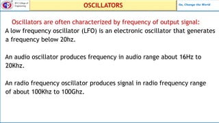
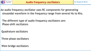
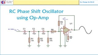
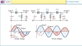
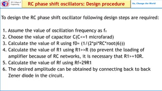
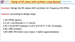
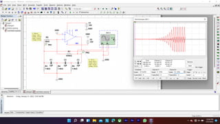
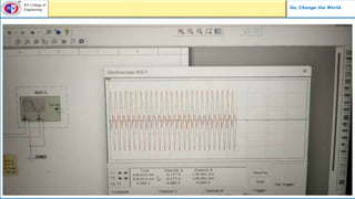
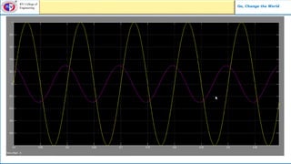
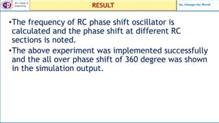
SUBMITTED TO
Adinath Jain
Dept. of Electrical and Electronics Engineering
Department of
Electrical & Electronics Engineering
RV College of
Engineering
Go, change the
world
EXPERIENTIAL LEARNING PRESENTATION
Course:- Analog Electronic Circuit (18EE33)
TOPIC
Using open source software simulate phase
shift oscillator and show relevant wave forms
RV College of
Engineering Go, Change the World
TEAM INTRODUCTION
PHOTO
MEMBER-1
PHOTO
MEMBER-2
PHOTO
MEMBER-3
PHOTO
MEMBER-4
USN Name Email Id
1RV20CV039 HARSH BHAN GIRI harshbhangiri.ee20@rvce.edu.in
1RV20CV042 HARSHIT MISHRA harshitmishra.ee20@rvce.edu.in
1RV20CV067 NIHAL GUPTA nihalgupta.ee20@rvce.edu.in
1RV20CV040 HARSHAD BIRADAR harshad.ee20@rvce.edu.in
RV College of
Engineering Go, Change the World
Presentation Outline
• Introduction
• Experimental Details
• Methodology
• Design and procedure
• Simulation work
• Output graph
RV College of
Engineering Go, Change the World
An electronic oscillator is an electronic circuit that produces a periodic
oscillating electronic signal, often a sine wave or a square wave or a
triangular wave.
Oscillators convert direct current(DC) from a power supply to an AC
signal.
They are widely used in many electronic devices ranging from simple
clock generators to digital instruments like calculator etc.
Common examples of signals generated by oscillators include signals
broadcast by radio and television transmitters,also in clock signals.
OSCILLATORS
RV College of
Engineering Go, Change the World
OSCILLATORS
Oscillators are often characterized by frequency of output signal:
A low frequency oscillator (LFO) is an electronic oscillator that generates
a frequency below 20hz.
An audio oscillator produces frequency in audio range about 16Hz to
20Khz.
An radio frequency oscillator produces signal in radio frequency range
of about 100Khz to 100Ghz.
RV College of
Engineering Go, Change the World
Audio frequency oscillators
An audio frequency oscillator uses RC components for generating
sinusoidal waveform in the frequency range from several Hz to Khz.
The different type of audio frequency oscillators are:
Phase-shift oscillators
Quadrature oscillators
Three phase oscillators
Wien bridge oscillators
RV College of
Engineering Go, Change the World
RC phase shift oscillator
A phase shift oscillator consists of an inverting amplifier with a positive
feedback. The amplifier gives a phase shift of 180 and the feedback gives
another phase shift of 180 so total phase shift is 360.
Signal that appears at inverting terminal is shifted by 180 at the output.
Therefor an additional phase shift of 180 is required for oscillation at
Specific frequency in order to give total phase shift of 360.
Since feedback path consists of resistors and capacitors this oscillator is
also RC oscillator.
RV College of
Engineering Go, Change the World
RV College of
Engineering Go, Change the World
RV College of
Engineering Go, Change the World
RC phase shift oscillators: Design procedure
To design the RC phase shift oscillator following design steps are required:
1. Assume the value of oscillation frequency as f0
2. Choose the value of capacitor C(C<=1 microfarad)
3. Calculate the value of R using f0= (1/(2*pi*RC*root(6)))
4. Calculate the value of R1 using R1>>R (to prevent the loading of
amplifier because of RC networks, it is necessary that R1>=10R.
5. Calculate the value of Rf using Rf=29R1
6. The desired amplitude can be obtained by connecting back to back
Zener diode in the circuit.
RV College of
Engineering Go, Change the World
Design of RC phase shift oscillator using Opamp
Example: Design the RC phase shift oscillator for frequency f0=197Hz
Solution: According to design steps:
1.f0=197Hz (given)
2.C=0.1 microfarad( C<=1 micro)
3.R=1/(2*pi*f0*C*root(6))=1/(2*3.414*19.7*.1*10^-6*root(6))
4.R1=10R=33 Kohm
5.Rf=29R1=957 kohm (we choose 1 Mohm approximately)
RV College of
Engineering Go, Change the World
RV College of
Engineering Go, Change the World
Video presentation
RV College of
Engineering Go, Change the World
RV College of
Engineering Go, Change the World
RV College of
Engineering Go, Change the World
RESULT
•The frequency of RC phase shift oscillator is
calculated and the phase shift at different RC
sections is noted.
•The above experiment was implemented successfully
and the all over phase shift of 360 degree was shown
in the simulation output.

oscillator (1) (1).pptx

  • 1.
    SUBMITTED TO Adinath Jain Dept.of Electrical and Electronics Engineering Department of Electrical & Electronics Engineering RV College of Engineering Go, change the world EXPERIENTIAL LEARNING PRESENTATION Course:- Analog Electronic Circuit (18EE33) TOPIC Using open source software simulate phase shift oscillator and show relevant wave forms
  • 2.
    RV College of EngineeringGo, Change the World TEAM INTRODUCTION PHOTO MEMBER-1 PHOTO MEMBER-2 PHOTO MEMBER-3 PHOTO MEMBER-4 USN Name Email Id 1RV20CV039 HARSH BHAN GIRI harshbhangiri.ee20@rvce.edu.in 1RV20CV042 HARSHIT MISHRA harshitmishra.ee20@rvce.edu.in 1RV20CV067 NIHAL GUPTA nihalgupta.ee20@rvce.edu.in 1RV20CV040 HARSHAD BIRADAR harshad.ee20@rvce.edu.in
  • 3.
    RV College of EngineeringGo, Change the World Presentation Outline • Introduction • Experimental Details • Methodology • Design and procedure • Simulation work • Output graph
  • 4.
    RV College of EngineeringGo, Change the World An electronic oscillator is an electronic circuit that produces a periodic oscillating electronic signal, often a sine wave or a square wave or a triangular wave. Oscillators convert direct current(DC) from a power supply to an AC signal. They are widely used in many electronic devices ranging from simple clock generators to digital instruments like calculator etc. Common examples of signals generated by oscillators include signals broadcast by radio and television transmitters,also in clock signals. OSCILLATORS
  • 5.
    RV College of EngineeringGo, Change the World OSCILLATORS Oscillators are often characterized by frequency of output signal: A low frequency oscillator (LFO) is an electronic oscillator that generates a frequency below 20hz. An audio oscillator produces frequency in audio range about 16Hz to 20Khz. An radio frequency oscillator produces signal in radio frequency range of about 100Khz to 100Ghz.
  • 6.
    RV College of EngineeringGo, Change the World Audio frequency oscillators An audio frequency oscillator uses RC components for generating sinusoidal waveform in the frequency range from several Hz to Khz. The different type of audio frequency oscillators are: Phase-shift oscillators Quadrature oscillators Three phase oscillators Wien bridge oscillators
  • 7.
    RV College of EngineeringGo, Change the World RC phase shift oscillator A phase shift oscillator consists of an inverting amplifier with a positive feedback. The amplifier gives a phase shift of 180 and the feedback gives another phase shift of 180 so total phase shift is 360. Signal that appears at inverting terminal is shifted by 180 at the output. Therefor an additional phase shift of 180 is required for oscillation at Specific frequency in order to give total phase shift of 360. Since feedback path consists of resistors and capacitors this oscillator is also RC oscillator.
  • 8.
    RV College of EngineeringGo, Change the World
  • 9.
    RV College of EngineeringGo, Change the World
  • 10.
    RV College of EngineeringGo, Change the World RC phase shift oscillators: Design procedure To design the RC phase shift oscillator following design steps are required: 1. Assume the value of oscillation frequency as f0 2. Choose the value of capacitor C(C<=1 microfarad) 3. Calculate the value of R using f0= (1/(2*pi*RC*root(6))) 4. Calculate the value of R1 using R1>>R (to prevent the loading of amplifier because of RC networks, it is necessary that R1>=10R. 5. Calculate the value of Rf using Rf=29R1 6. The desired amplitude can be obtained by connecting back to back Zener diode in the circuit.
  • 11.
    RV College of EngineeringGo, Change the World Design of RC phase shift oscillator using Opamp Example: Design the RC phase shift oscillator for frequency f0=197Hz Solution: According to design steps: 1.f0=197Hz (given) 2.C=0.1 microfarad( C<=1 micro) 3.R=1/(2*pi*f0*C*root(6))=1/(2*3.414*19.7*.1*10^-6*root(6)) 4.R1=10R=33 Kohm 5.Rf=29R1=957 kohm (we choose 1 Mohm approximately)
  • 12.
    RV College of EngineeringGo, Change the World
  • 13.
    RV College of EngineeringGo, Change the World Video presentation
  • 14.
    RV College of EngineeringGo, Change the World
  • 15.
    RV College of EngineeringGo, Change the World
  • 16.
    RV College of EngineeringGo, Change the World RESULT •The frequency of RC phase shift oscillator is calculated and the phase shift at different RC sections is noted. •The above experiment was implemented successfully and the all over phase shift of 360 degree was shown in the simulation output.