CAD CAM II
Computer-aided design (CAD) is the use of computer systems to
assist in the creation, modification, analysis, or optimization of a design. CAD output is often in
the form of electronic files for print, machining, or other manufacturing operations. Computer-
aided design can also be known as computer-aided drafting (CAD) which describes the process
of creating a technical drawing with the use of computer software.
Computer-aided manufacturing (CAM) is the use of
software to control machine tools and related machinery in the manufacturing of workpieces. Its
primary purpose is to create a faster production process and components and tooling with more
precise dimensions and material consistency, which in some cases, uses only the required
amount of raw material (thus minimizing waste), while simultaneously reducing energy
consumption
3d modeling:
Rhino can create, edit, analyze, document,
render, animate, and translate NURBS
curves, surfaces, and solids with no limits on
complexity, degree, or size. Rhino also
supports polygon meshes and point clouds.
This makes Rhino one of the most universal
3D modeling packages on the market today.
Architecture:
Objects:
Engineering:
Polygon mesh versus NURBS
Organic Sculpting
Parametric modeling
Nervous system
http://n-e-r-v-o-u-s.com/
Laser Cutting: Laser cutting is a
technology that uses a laser to cut materials,
and is typically used for industrial
manufacturing applications. Laser cutting
works by directing the output of a high
power laser, by computer, at the material to
be cut. The material then either melts, burns,
vaporizes away, or is blown away by a jet of
gas, leaving an edge with a high quality
surface finish.
Vector art
Kat Wilson
Laser cut, stack laminated cuff, 3D scan data
Arthur Hash
Laser cut acrylic
3d scanning:
Using laser imaging to scan 3D
mesh/surfaces. Mainly used in
medical and anthropological
settings, where actually touching
an object would be devastating.
Photogrammetry: making surfaces from 2D digital photos
 In 1984, Chuck Hull of 3D Systems Corporation[11]
 developed a prototype system based on a process 
known as stereolithography, in which layers are added by curing photopolymers with ultraviolet light 
lasers. Hull defined the process as a "system for generating three-dimensional objects by creating a 
cross-sectional pattern of the object to be formed,
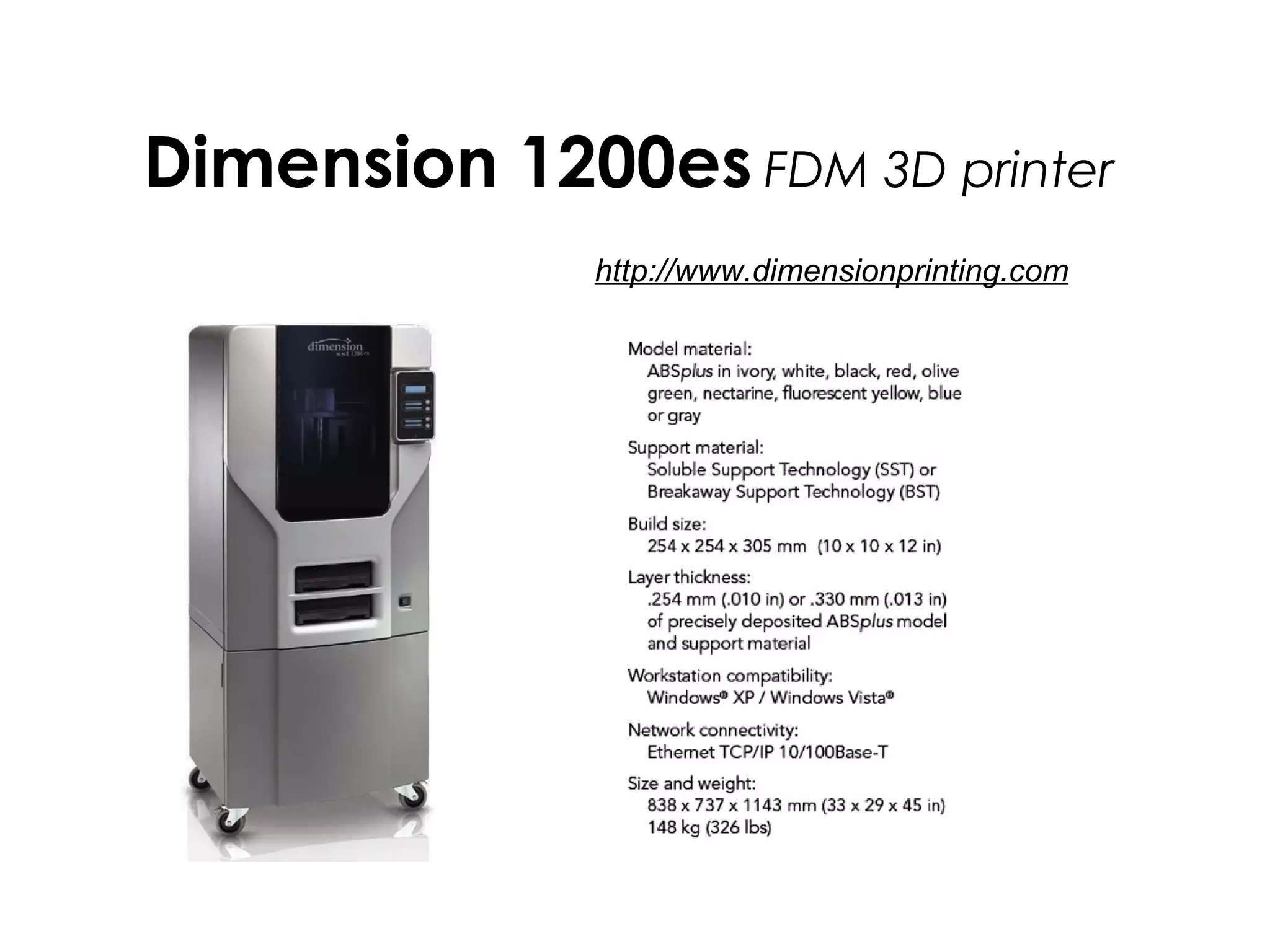
There are presently about 25 different 3D printing technologies. The oldest is probably 
stereolithography. More recent technologies include selective laser sintering, inkjet technologies, 
fused deposition modeling and many variations. All of these technologies take a 3D model, compute 
cross-sections of that model, and then deposit the cross-sections sequentially on top of each other 
until the final geometry is achieved.
To visualize how 3D printing works, consider slicing a ham on a meat slicing machine. The slices are 
cross-sections which can be stacked to reproduce the form of the original ham.
3d printing: STARTED IN THE 80s
Advantages
1.) Energy efficiency: Only the energy necessary to form the part is expended, and waste is 
eliminated. This contrasts with conventional machining, in which energy is used to smelt metal into 
ingots, which become billet materials. These billet materials are then machined, removing a great 
deal of the material to produce the final part. The energy used to create the original block of material 
is wasted.
2.) Low material waste: Since the process only forms the desired part, there is almost no waste 
formed, again in contrast to conventional machining. The absence of waste enhances energy 
efficiency, as energy is not used to transport or dispose of waste.
 
SLA (Stereolithography Apparatus) – Process using photosensitive resins cured by a laser that 
traces the parts cross sectional geometry layer by layer. SLA produces accurate models with a variety 
of material choices.
SLS (Selective Laser Sintering) – Process using a CO2 laser to sinter or fuse a powder material. 
The laser traces the parts cross sectional geometry layer by layer. SLS creates accurate and durable 
parts but finish out of machine is relatively poor.
FDM (Fused Deposition Modeling) – Process using molten plastics or wax extruded by a nozzle that 
traces the parts cross sectional geometry layer by layer. FDM creates tough parts that are ideal for 
functional usage.
ZCorp (Z-Corp Three-Dimensional Printing) – Ink-jet based process that prints the parts cross 
sectional geometry on layers of powder spread on top of each other. This process enables models to 
be built quickly and affordably. Models may also be printed in color.
PJET (Polyjet) – This process is similar to stereolithography in that parts are made with a 
photosensitive resin. The difference is in how the resin is applied and cured to build the part. 
Dimension 1200es FDM 3D printer
http://www.dimensionprinting.com
Formlabs SLA 3D printer
ASIGA Pico2 SLA 3D printer
Projects
Commemorative coin
Conceptual renderings
Commemorative coin
3D printed in wax, cast in white bronze and hand finished in the Metal program
Commemorative coin
3D printed in wax, cast in white bronze and hand finished in the Metal program
Phil Renato
Doug Bucci:
David Choi
Emily Cobb
• Students will be proficient in CAD drawing, 3D printing, 3D scanning,
laser cutting and digital rendering through completing design problem
assignments, samples and final projects.
• Students will solve design problems by discussing examples of
contemporary work made using digital fabrication techniques
• Students will use on-campus facilities to better understand outsourcing
file formatting standards for outsourcing to industry
• Students will develop a digital fabrication work flow when designing and
fabricating objects
• Students will develop the ability to assess, analyze, and articulate a
critical approach to digital fabrication in a written and verbal form through
research, hands-on fabrication and peer evaluation.
• Blogger, Tumblr, Flickr and Sketchfab
• Rhino, Grasshopper and Sculptris
• Dimension, Asiga, Form1&2, CubePro
• Sense scanner, vinyl cutter, laser engraver
• Shapeways, Thingiverse, Imaterialise and
Kraftwurx
NECK-IT!
Assignment brief: Using Rhino, Shapeways and historical references to design and 3D print a fully articulated
necklace in one piece.
 
Learning outcomes: Students will learn advanced modeling techniques in Rhino, file formatting for outsourcing 3D
printing and be exposed to new materials by designing a wearable neck piece using 3D printing. This process will better inform
future design decisions using this workflow.
 
Skills list: Rhino: Array along curve, History, advanced gumball, orientation, model extents, connection points, checking
models for printability and sudo-parametric modeling, flow along surface, sweep1 and 2
 
Shapeways: uploading, workflow, pricing, tolerances, printing in multiple materials and breaking points in materials
Concept: Creating a necklace with interlocking parts has the ability to create multiple narratives through repetition,
generative geometry, historical reference and wear-ability. Using 3D printing and CAD modeling there is an opportunity to make
new forms that move beyond a basic metals skillset. This project will ask to student to explore new territory that may have been
closed off to them through traditional fabrication methods.
Research: Chains, contemporary work, connection points/links, status symbols, focal points (such as medallions), clasps,
cultural identifiers, fashion
Questions:
How many links does something need to be a necklace?
Does it need to connect all the way (clasp, over the head etc)?
What are the advantages of multiples?
What range of motion does it need to have?
How big are the links?
What is the history of the necklace?
 
Expectations: A fully articulated 3D printed chain with a clasp, Research in the form of models, photos, chain samples and tests
Documentation in the form of digital renderings, Rubber mold of one link.
Ludovico Lombardi
LACE Jenny Wu
Michiel Cornelissen ontwerp
Daniel Widrig
CAD/CAM II
CAD/CAM II
CAD/CAM II
CAD/CAM II
CAD/CAM II
CAD/CAM II
CAD/CAM II

CAD/CAM II