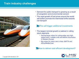
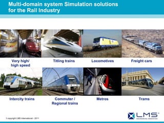
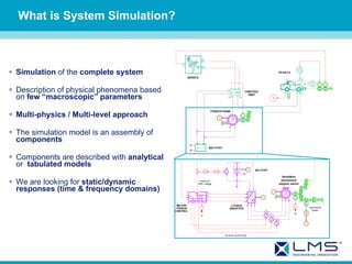
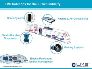
LMS Simulation Division Multi-domain System Simulation Solutions for Railway
Train industry challenges Demand for public transport is growing as a result of congestion and environmental concern The rapid growth of fuel prices around the world will further promote the intermodal shifts towards rail transport This will trigger additional investments The largest nominal growth is realized in rolling stock segments Several large orders for cutting-edge very high-speed trains, multiple units and electric locomotive in Western Europe Big orders for metro cars in Asia, NAFTA and Africa/Middle East How to deliver cost efficient development?   copyright  LMS  International - 2011
Multi-domain system Simulation solutions for the Rail Industry Very high/ high speed   Titling trains   Commuter /  Regional trains   Locomotives   Freight cars   Metros   Trams   Intercity trains   copyright  LMS  International - 2011
What is System Simulation? Simulation  of the  complete system Description of physical phenomena based on  few “macroscopic” parameters Multi-physics / Multi-level approach The simulation model is an assembly of  components Components are described with  analytical  or  tabulated   models We are looking for  static/dynamic responses (time & frequency domains)
The Multi-physics Compatible elements  can be connected Exemple : Electro-hydrostatic actuator
The Multi-level (scalability) Various complexity scale for various development objective Modeling focus Development objective Pre-sizing, control strategy development System sizing, control  Component optimization Quasi-static: map models Low frequency: prevailing behaviors High frequency: detailed dynamics level of Detail = level of complexity Physical Modeling: From Functional Specification to Calibration.
LMS Solutions for Rail / Train Industry Shock Absorber Suspension Braking Systems Heating & Air-Conditioning Doors Systems Electric Powertrain  Energy Management   copyright  LMS  International - 2011
Performance and Energy consumption Models for global vehicle architecture definition Prediction of losses to improve consumption Off-line test procedure validation (HIL or/and SIL) Fully interfaced with Matlab/Simulink and common real-time platforms (dSPACE, Opal RT, xPC Target) Flexible post-processing results   copyright  LMS  International - 2011
Example of Rankine cycle system with R134a Energy Recovery 20°C   copyright  LMS  International - 2011 90°C 400°C
Electrical Machines: from Pre-design  to Motor torque control Average model of machine using reference table of losses Physical motor model, inverter and torque control models
Electrical Harnesses Cable Problem High conductor resistance leads to thermal losses Mass is proportional to conductor area Using the AMESim Libraries to simulate: Heat flow (Joules Law) Deviation  from Ideal Resistance Voltage Drop, actual supplied voltage Ambient Heating Adapting to … Thermal Physical  Electric … Constraints Internal Exchange External Exchange Branche 1 Branche 2 Branche 3 BUS BAR
Electronic Rack Cooling Cooling system sizing Temperature estimation of electronic component   copyright  LMS  International - 2011
Heating & Air-Conditioning Refrigerant loop design Network sizing Definition of the System control using physical models AC components sizing Interface and influence on cabins interior   copyright  LMS  International - 2011
Braking Systems Design of any types of Braking Systems Air brake Vacuum brake Dynamic brake Parking brake Simulate complex and highly non-linear system such a whole train braking system  Evolution of pressure and temperature in the pneumatic line Compressor: Evolution of Mass flow rate, pressure and volume   copyright  LMS  International - 2011
Shock Absorber - Suspension Model of the Chassis in AMESim or interface with internal code or multibody Software   copyright  LMS  International - 2011
Chassis - Body Tilting systems with hydraulic or pneumatic actuation.   copyright  LMS  International - 2011
References Modeling of components for train pneumatic  braking systems:  three-way two-position, electrically controlled valves,  relay valves ,  wheel slide protection valve and the integration in the complete system .Analyze of functions, static and dynamic behavior Assessment of the behavior of the braking system under different conditions like failures  Test of various architectures, excluding parts of the system or integrating it with new designed devices Simulating pneumatic brake systems and a nalysis of the processes regarding the dimensioning of the braking system Components design and interaction analysis System optimization: dimensions, functionality Precise mapping of the relay valve with mass oscillations Simulation of railway brake plants Modeling, analysis and calibration of the  complex pneumatic plant Performance and reliability analysis in every operating conditions Test and  simulation of the response of a convoy composed by SAADKMS freight wagon Design of energy recovery systems for traction and drive architectures Model of all the system components (closed steam circuit, piston expander, integrated condenser, EGR and exhaust) and study the system behavior Assessment of the thermodynamic Rankine cycle, as well as controls and full vehicle integration    copyright  LMS  International - 2011
Braking Systems LMS Imagine.Lab AMESim model of Metro Merval pneumatic braking system     copyright  LMS  International - 2011
VOITH TURBO  uses LMS Imagine.Lab AMESim to develop  hybrid drive train applications for Trains Challenges Design  energy recovery systems  for traction and drive architectures Model all the system components (closed steam circuit, piston expander, integrated condenser, EGR and exhaust) and study the system behavior Assess  thermodynamic Rankine cycle , as well as controls and full vehicle integration  Solutions LMS Imagine.Lab Two-Phase Flow Systems Benefits Seamlessly  model systems with Rankine cycle  and assess their performance during full load acceleration cycle Study the behavior of  different operating modes and strategies  (downsizing, hybrid off, boost hybrid)  and their influence on  power  and  fuel consumption  “ LMS Imagine.Lab AMESim enables us to assess different hybrid technologies and their specific capabilities, especially heat recovery systems, early in the design process .” Sebastian KNIRSCH – VOITH TURBO – Engineering Services   copyright  LMS  International - 2011
Thank you

Rail Simulation System

  • 1.
    LMS Simulation DivisionMulti-domain System Simulation Solutions for Railway
  • 2.
    Train industry challengesDemand for public transport is growing as a result of congestion and environmental concern The rapid growth of fuel prices around the world will further promote the intermodal shifts towards rail transport This will trigger additional investments The largest nominal growth is realized in rolling stock segments Several large orders for cutting-edge very high-speed trains, multiple units and electric locomotive in Western Europe Big orders for metro cars in Asia, NAFTA and Africa/Middle East How to deliver cost efficient development? copyright LMS International - 2011
  • 3.
    Multi-domain system Simulationsolutions for the Rail Industry Very high/ high speed Titling trains Commuter / Regional trains Locomotives Freight cars Metros Trams Intercity trains copyright LMS International - 2011
  • 4.
    What is SystemSimulation? Simulation of the complete system Description of physical phenomena based on few “macroscopic” parameters Multi-physics / Multi-level approach The simulation model is an assembly of components Components are described with analytical or tabulated models We are looking for static/dynamic responses (time & frequency domains)
  • 5.
    The Multi-physics Compatibleelements can be connected Exemple : Electro-hydrostatic actuator
  • 6.
    The Multi-level (scalability)Various complexity scale for various development objective Modeling focus Development objective Pre-sizing, control strategy development System sizing, control Component optimization Quasi-static: map models Low frequency: prevailing behaviors High frequency: detailed dynamics level of Detail = level of complexity Physical Modeling: From Functional Specification to Calibration.
  • 7.
    LMS Solutions forRail / Train Industry Shock Absorber Suspension Braking Systems Heating & Air-Conditioning Doors Systems Electric Powertrain Energy Management copyright LMS International - 2011
  • 8.
    Performance and Energyconsumption Models for global vehicle architecture definition Prediction of losses to improve consumption Off-line test procedure validation (HIL or/and SIL) Fully interfaced with Matlab/Simulink and common real-time platforms (dSPACE, Opal RT, xPC Target) Flexible post-processing results copyright LMS International - 2011
  • 9.
    Example of Rankinecycle system with R134a Energy Recovery 20°C copyright LMS International - 2011 90°C 400°C
  • 10.
    Electrical Machines: fromPre-design to Motor torque control Average model of machine using reference table of losses Physical motor model, inverter and torque control models
  • 11.
    Electrical Harnesses CableProblem High conductor resistance leads to thermal losses Mass is proportional to conductor area Using the AMESim Libraries to simulate: Heat flow (Joules Law) Deviation from Ideal Resistance Voltage Drop, actual supplied voltage Ambient Heating Adapting to … Thermal Physical Electric … Constraints Internal Exchange External Exchange Branche 1 Branche 2 Branche 3 BUS BAR
  • 12.
    Electronic Rack CoolingCooling system sizing Temperature estimation of electronic component copyright LMS International - 2011
  • 13.
    Heating & Air-ConditioningRefrigerant loop design Network sizing Definition of the System control using physical models AC components sizing Interface and influence on cabins interior copyright LMS International - 2011
  • 14.
    Braking Systems Designof any types of Braking Systems Air brake Vacuum brake Dynamic brake Parking brake Simulate complex and highly non-linear system such a whole train braking system Evolution of pressure and temperature in the pneumatic line Compressor: Evolution of Mass flow rate, pressure and volume copyright LMS International - 2011
  • 15.
    Shock Absorber -Suspension Model of the Chassis in AMESim or interface with internal code or multibody Software copyright LMS International - 2011
  • 16.
    Chassis - BodyTilting systems with hydraulic or pneumatic actuation. copyright LMS International - 2011
  • 17.
    References Modeling ofcomponents for train pneumatic braking systems: three-way two-position, electrically controlled valves, relay valves , wheel slide protection valve and the integration in the complete system .Analyze of functions, static and dynamic behavior Assessment of the behavior of the braking system under different conditions like failures Test of various architectures, excluding parts of the system or integrating it with new designed devices Simulating pneumatic brake systems and a nalysis of the processes regarding the dimensioning of the braking system Components design and interaction analysis System optimization: dimensions, functionality Precise mapping of the relay valve with mass oscillations Simulation of railway brake plants Modeling, analysis and calibration of the complex pneumatic plant Performance and reliability analysis in every operating conditions Test and simulation of the response of a convoy composed by SAADKMS freight wagon Design of energy recovery systems for traction and drive architectures Model of all the system components (closed steam circuit, piston expander, integrated condenser, EGR and exhaust) and study the system behavior Assessment of the thermodynamic Rankine cycle, as well as controls and full vehicle integration copyright LMS International - 2011
  • 18.
    Braking Systems LMSImagine.Lab AMESim model of Metro Merval pneumatic braking system copyright LMS International - 2011
  • 19.
    VOITH TURBO uses LMS Imagine.Lab AMESim to develop hybrid drive train applications for Trains Challenges Design energy recovery systems for traction and drive architectures Model all the system components (closed steam circuit, piston expander, integrated condenser, EGR and exhaust) and study the system behavior Assess thermodynamic Rankine cycle , as well as controls and full vehicle integration Solutions LMS Imagine.Lab Two-Phase Flow Systems Benefits Seamlessly model systems with Rankine cycle and assess their performance during full load acceleration cycle Study the behavior of different operating modes and strategies (downsizing, hybrid off, boost hybrid) and their influence on power and fuel consumption “ LMS Imagine.Lab AMESim enables us to assess different hybrid technologies and their specific capabilities, especially heat recovery systems, early in the design process .” Sebastian KNIRSCH – VOITH TURBO – Engineering Services copyright LMS International - 2011
  • 20.

Editor's Notes

  • #3 Copyright LMS International
  • #5 Please chose between the following slides the best appropriate slide according your audience. The key messages of the slide: 1/ We give our System Simulation definition * System : A set of components combined together to fulfill a main targeted function requested by customer. * Simulation : A representation of a system by means of physical and mathematical computer based models The physical model is based on a simplified (but not simple) representation of the physical behavior of the component. Parameters and variables are then reduced to ones of interest. It is however usual to combine different levels of modeling based on data available, physics or technology to be represented.
  • #11 Copyright LMS International The submodel dedicated to the pre-sizing stage has been replaced with a detailed powertrain model based on physical equations. A new control unit has been designed to be compatible with the electric machine torque control. Electrical machine: The electrical machine is a salient-pole permanent magnet synchronous machine. The model is linear: the magnetic material saturation is neglected. Parameters are now physical ones (  open the demo and show the parameters) Demos  solution demos  electromechanical  electric vehicle step2 phase inverter: The 3 phase inverter model uses the diodes and transistors static electrical characteristic as parameters. The losses can therefore accurately be computed from the commuters manufacturer datasheet. The switching dynamics (very high frequency) are averaged in order to be able to simulate lond driving cycles in little CPU time. Machine torque control: The machine torque control is based on field oriented vector control, adapted to the machine model used. It computes the voltage command for the inverter to apply to the machine to reach the motor or generator torque request.
  • #12 Electrical connection with 2 commuters enables to have 2 current paths: up and down
  • #18 Copyright LMS International