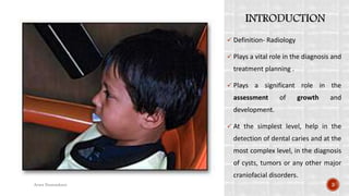
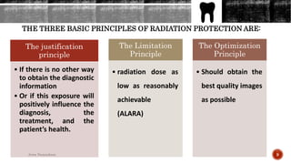
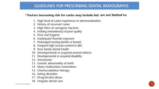
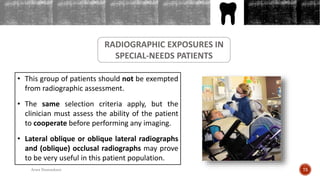
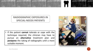
Arwa Mohammed Namnakani
R1 – 2019-
OUTLINES
 INTRODUCTION.
 HISTORY
 RADIATION SAFETY AND PROTECTION.
 RADIOGRAPHIC IMAGE RECEPTORS.
 RADIOGRAPHIC TECHNIQUES.
 INTERPRETATION OF RADIOGRAPHS
 SELECTION CRITERIA AND RADIOGRAPHIC
2Arwa Namnakani
 Definition- Radiology
 Plays a vital role in the diagnosis and
treatment planning .
 Plays a significant role in the
assessment of growth and
development.
 At the simplest level, help in the
detection of dental caries and at the
most complex level, in the diagnosis
of cysts, tumors or any other major
craniofacial disorders.
3Arwa Namnakani
WILHELM
CONRAD
ROENTGEN
1845 - 1923
The first radiograph – Mrs. Roentgen’s hand
5
6Arwa Namnakani
7Arwa Namnakani
THE THREE BASIC PRINCIPLES OF RADIATION PROTECTION ARE:
The justification
principle
• If there is no other way
to obtain the diagnostic
information
• Or if this exposure will
positively influence the
diagnosis, the
treatment, and the
patient’s health.
The Limitation
Principle
• radiation dose as
low as reasonably
achievable
(ALARA)
The Optimization
Principle
• Should obtain the
best quality images
as possible
9Arwa Namnakani
There are two
models have been
devised to explain
the effects of
radiation:
1- Non-threshold model
• It suggests that any dose of x-rays can cause
biological damage
2- Threshold model
• It suggests that no detrimental effects of ionizing
radiation occur below a particular level or
“threshold” of x-ray exposure.
• which means that a certain amount of radiation is
necessary before the response can be seen.
10Arwa Namnakani
11Arwa Namnakani
Primary biological effects of
low-level radiation
Carcinogenesis Teratogenesis Mutagenesis
Somatic tissues Genetic tissue (gonads)
Have a threshold response
Sensitive to ionizing
radiation and are
believed to have no
threshold
(stochastic effects).
12Arwa Namnakani
PROTECTION OF THE DENTAL STAFF
-The best method for protecting dental staff from ionizing
radiation is the use of shielding or solid walls (preferably with a
lead glass window). However, some offices lack such walls, and
the radiographer must maintain a safe distance from the x-ray
source.
-The radiographer should stand either at 90° to or behind the
radiation source; at least 6 feet (2 m) from the radiation source.
-The 6-foot rule also applies to panoramic and cephalometric
imaging. For CBCT imaging, one should always stand behind a
radioprotective barrier.
13Arwa Namnakani
14
Arwa Namnakani
In addition to the three basic principles of radiation protection
(justification, limitation, and optimization), one can apply the following additional
techniques to reduce the radiation burden to the patient:
o Collimation of the x-ray beam
o More radiation-sensitive image receptors
o Lead apron with thyroid collar
PROTECTION OF THE
PATIENT
o Correct focus-to-skin distance15
Arwa Namnakani
16
Arwa Namnakani
Collimation of the x-ray beam
-Collimator is the metallic barrier (usually lead) that used to reduce
the size of the x-ray beam and thereby the volume of irradiated
tissue.
-The use of rectangular collimation limits the surface being
irradiated to the size of the image receptor, reducing the radiation
dose by about 50%, compared with the (6 cm) circular collimator.
17Arwa Namnakani
Collimation of the x-ray beam
18
Arwa Namnakani
focus-to-skin distance
(A minimum of 8 inches (20 cm))
19Arwa Namnakani
Lead apron with thyroid collar
20Arwa Namnakani
OUTLINES
• Lead apron with thyroid collar
ICRP guidelines suggest that the use of a lead apron is not
necessary with rectangular collimation, short exposure times,
adequate x-ray energies, and fast image receptors.
21Arwa Namnakani
• More radiation-sensitive image receptors
- Always try to use fast image receptors, which require less exposure time.
- Use of digital image receptors and E or F speed films are advised.
PROTECTION OF THE PATIENT
More radiation-sensitive image receptors
PROTECTION OF THE PATIENT
23Arwa Namnakani
RADIOGRAPHIC IMAGE
RECEPTORS
OUTLINES
RADIOGRAPHIC IMAGE
RECEPTORS
ANALOG FILM DIGITAL FILM
Direct film
Indirect film
Photo-stimulable phosphor
storage plates (PSPPs)
Solid-state sensors
25Arwa Namnakani
ANALOG FILM
Direct film
- Used for intraoral radiography. It is called direct because of its high sensitivity
to x-rays. It comes in different sizes (0 – 4):
- (ISO format 0): bitwing and periapical in 1ry dentition (also called pedo size).
- (ISO format 1): used for the same purpose as size 0 .
- (ISO format 2): bitwing and periapical in mixed and permanent dentition and
occlusal radiograph of 1ry dentition (the most common size used).
- (ISO format 3): used only for bitewing images in the mixed and permanent
dentition.
- (ISO format 4): occlusal radiograph for mixed and permanent dentition.
26Arwa Namnakani
ANALOG FILM
Direct film
27Arwa Namnakani
ANALOG FILM
Indirect film
- Indirect analog film is sensitive to light more than x-rays and for this
reason it should be used only in a cassette with an intensifying screen.
- The intensifying screen converts the x-ray energy into light, which reaches
the film and forms the latent image.
- Used in panoramic imaging and cephalometric radiography.
28Arwa Namnakani
OUTLINES
ANALOG FILM
Indirect film
Intensifying screen 29Arwa Namnakani
OUTLINES
DIGITAL FILM
Photo-stimulable phosphor storage plates (PSPPs)
- Very similar to analog film and also come in different sizes
- Also referred to as indirect digital imaging because the image is captured
in an analog format and converted to a digital image.
30Arwa Namnakani
DIGITAL FILM
Photo-stimulable phosphor storage plates (PSPPs)
31Arwa Namnakani
DIGITAL FILM
Photo-simulable phosphor storage plates (PSPPs)
Phosphor plate that
has been bitten
Phosphor plate image with
several bitemarks
and scratches
DIGITAL FILM
Solid-state sensors
- Known as direct digital receptors because they display the radiographic
image instantaneously following exposure.
- Available in sizes 0, 1, and 2.
- The primary disadvantage is: bulky and not always easy to position in the
patient’s mouth
33Arwa Namnakani
SOLID-STATE
SENSORS 34Arwa Namnakani
35Arwa Namnakani
RADIOGRAPHIC
TECHNIQUES
INTRAORAL RADIOGRAPHY
Periapical Radiography
Bitewing Radiography
Anterior Maxillary
Occlusal Technique
Posterior Maxillary
Occlusal Technique
Anterior Mandibular
Occlusal Technique
Oblique Occlusal
Radiography
Localization
Techniques
Panoramic Imaging
EXTRAORAL RADIOGRAPHY
Medical Computed
Tomography
Cephalometric Imaging
Oblique Lateral Radiography
Cone Beam Computed
Tomography
Ultrasound Imaging
Magnetic Resonance Imaging
RADIOGRAPHIC TECHNIQUES
37Arwa Namnakani
OUTLINES
INTRAORAL RADIOGRAPHY
Periapical Radiography
Bisecting Angle TechniqueParalleling Technique
Periapical radiographs should show the crown of the tooth
and at least 3 mm beyond the apex of the tooth.
To achieve this coverage, one can use either:
38Arwa Namnakani
1- Paralleling Technique
- The most accurate technique for taking intraoral radiographs.
- The image receptor should be positioned parallel to the long axis of the
teeth, while the x-ray beam is directed perpendicular to the image receptor.
- Ideally, image receptor holders that enable one to aim easily and correctly
should be used.
39Arwa Namnakani
1- Paralleling Technique
40Arwa Namnakani
2- Bisecting Angle Technique
- The image receptor is placed as close to the teeth as possible, and the x-ray
beam is directed perpendicular to a line that bisects the angle created by the
tooth and image receptor.
- This technique has more geometric errors (e.g. elongation, overlap) and
should not be regarded as the preferred technique.
41Arwa Namnakani
Bisecting Angle Technique
43Arwa Namnakani
Periapical Radiography
44Arwa Namnakani
INTRAORAL RADIOGRAPHY
Bitewing Radiography
- Assess interproximal caries and interproximal bone height.
- Based on the paralleling technique.
- Image receptor holders that enable one to aim easily and correctly should be used.
45Arwa Namnakani
INTRAORAL RADIOGRAPHY
Bitewing Radiography
46Arwa Namnakani
INTRAORAL RADIOGRAPHY
Bitewing Radiography
47Arwa Namnakani
INTRAORAL RADIOGRAPHY
Anterior Maxillary Occlusal Technique
- The patient’s occlusal plane should be parallel to the floor, and the sagittal plane
should be perpendicular to the floor.
- Size 2 image receptor is used and the patient is instructed to bite lightly to hold
the receptor.
- The anterior edge of the receptor should extend approximately 2 mm in front of
the incisal edge of the central incisors.
- The x-ray beam is directed to the apices of the central incisors with the vertical
angle being +60° . 48Arwa Namnakani
INTRAORAL RADIOGRAPHY
Anterior Maxillary Occlusal Technique
49Arwa Namnakani
INTRAORAL RADIOGRAPHY
Anterior Maxillary Occlusal Technique
50Arwa Namnakani
INTRAORAL RADIOGRAPHY
Posterior Maxillary Occlusal Technique
The same as anterior maxillary occlusal technique.
The anterior edge of the receptor should extend just mesial to the
canine.
The x-ray beam is directed toward the apices of the primary molars
with the vertical angle being +50°.
51Arwa Namnakani
INTRAORAL RADIOGRAPHY
Anterior Mandibular Occlusal Technique
• The film placement for the anterior mandibular occlusal technique is
identical to that for the anterior maxillary occlusal technique, except
that the receptor must be placed so that the tube side faces the x-ray
source.
• When the patient bites on the receptor, the anterior edge of the
receptor is 2 mm beyond the incisal edge of the lower incisors.
52Arwa Namnakani
Anterior Mandibular Occlusal Technique
53Arwa Namnakani
INTRAORAL RADIOGRAPHY
Oblique Occlusal Radiography
Based on the bisecting angle technique.
Good alternative for patients with a severe gag reflex or who cannot tolerate the
positioning of the image receptor holder device.
It obtained by positioning the patient so that the occlusal plane is parallel to the
floor. Aim the x-ray beam perpendicular to the bisecting line between the long axis
of the tooth and the axis of the occlusal plane.
The result of this technique is a periapical view of the posterior teeth. 54Arwa Namnakani
INTRAORAL RADIOGRAPHY
Oblique Occlusal Radiography
55Arwa Namnakani
INTRAORAL RADIOGRAPHY
Localization Technique (SLOB)
 This technique is used to localize embedded or unerupted teeth.
 Also called parallax technique.
 The SLOB role states that the image of any buccally oriented object appears to move in the
opposite direction from a moving x-ray source.
 The practitioner should make two radiographs of the unerupted tooth, the first one is taken
by the paralleling technique. The second film is placed in the mouth in the same position as
the first film, with the patient’s head position remaining the same, but with the horizontal
angle shifted either anteriorly or posteriorly depending on the site.
56Arwa Namnakani
INTRAORAL RADIOGRAPHY
Localization Technique
SLOB Technique
57Arwa Namnakani
Panoramic Imaging
EXTRAORAL RADIOGRAPHY
Useful alternative when a patient
cannot tolerate the intraoral image
receptor.
Can give a bitewing look-alike images.
It should not be used as a standard
bitewing radiograph because
panoramic images are magnified (by a
factor of around 1.3).
58Arwa Namnakani
Cephalometric Imaging
EXTRAORAL RADIOGRAPHY
 Usually used in orthodontics and
orthognathic surgery.
59Arwa Namnakani
Oblique Lateral Radiography
EXTRAORAL RADIOGRAPHY
Excellent alternative to bitewing, periapical, or panoramic images, when patients are
unable to tolerate these techniques.
Should not be regarded as a standard for every patient.
Special-needs patients and small children can definitely benefit from this technique.
The technique requires the film to be held parallel to the midsagittal plane of the
patient, while the x-ray beam is directed perpendicular to the cassette from behind
or below the mandibular body. 60Arwa Namnakani
Oblique Lateral Radiography
EXTRAORAL RADIOGRAPHY
61Arwa Namnakani
Cone Beam Computed Tomography
EXTRAORAL RADIOGRAPHY
Ideal for imaging
hard tissues.
62Arwa Namnakani
Cone Beam Computed Tomography
EXTRAORAL RADIOGRAPHY
63Arwa Namnakani
Medical Computed Tomography
EXTRAORAL RADIOGRAPHY
Useful for the imaging of hard and soft tissues.
Responsible for the highest radiation doses a
patient can receive from diagnostic imaging.
Usually used to identify malignancies, tumors,
and other symptoms of pathology, with or
without the use of contrast medium.
64Arwa Namnakani
Ultrasound Imaging
EXTRAORAL RADIOGRAPHY
Most people associate ultrasound imaging
with pregnancy, but this technique also is
excellent for investigation of soft tissues,
such as the floor of the mouth, salivary
glands, and lymph nodes in the head and
neck region. Since the technique does not
involve ionizing radiation, it can be
repeated as many times as necessary,
without exposing the patient to any risks.
65Arwa Namnakani
Magnetic Resonance Imaging
EXTRAORAL RADIOGRAPHY
This technique is especially useful
with soft tissue.
The most common dental
indication for the use of MRI is
for imaging the soft tissues of the
temporomandibular joint.
66Arwa Namnakani
INTERPRETATION OF
RADIOGRAPHS
OUTLINES
Radiographs should be evaluated under ideal conditions.
Density and contrast enhancements are essential tools for the assessment of digital
images.
Software filters can also assist in obtaining better images, but one should never
overlook the fact that filtering means loss of information.
The initial diagnosis should not be made at the chair side monitor, but rather in an
area of the office where the light is dimmed.
In case one has an image that cannot be diagnosed, the assistance of an oral and
maxillofacial radiologist may be advisable.
68Arwa Namnakani
SELECTION CRITERIA AND
RADIOGRAPHIC EXAMINATIONS
• For all radiographic examinations, justification and professional judgment on
an individual patient basis should apply.
• There are no guidelines per age group, gender, or dentition stage.
The American Dental Association (ADA), the American Academy for Pediatric
Dentistry (AAPD), the European Academy for Pediatric Dentistry (EAPD), and
other organizations have published criteria to guide the dental professional in
decision-making regarding appropriate radiographic imaging:
 These guidelines clearly state that if the patient cannot cope with the
procedure, one should attempt other strategies to handle the situation.
CRITERIA FOR EXPOSING CHILDREN TO IONIZING RADIATION
70Arwa Namnakani
 In some cases, radiographs are not possible, one should balance
the benefit against the risk even more carefully.
 Sometimes it is better to postpone the radiographic exposure
until the patient is older or better conditioned.
 The guidelines also clearly state that if there are no clinical signs
of pathology, the need for a radiographic assessment is up to the
professional’s judgment on an individual patient basis.
 Radiographs are never to be used for economic and screening
reasons since they involve a potential health risk for the patient.
71Arwa Namnakani
72Arwa Namnakani
73Arwa Namnakani
74Arwa Namnakani
OUTLINES
RADIOGRAPHIC EXPOSURES IN
SPECIAL-NEEDS PATIENTS
• This group of patients should not be exempted
from radiographic assessment.
• The same selection criteria apply, but the
clinician must assess the ability of the patient
to cooperate before performing any imaging.
• Lateral oblique or oblique lateral radiographs
and (oblique) occlusal radiographs may prove
to be very useful in this patient population.
75Arwa Namnakani
OUTLINES
RADIOGRAPHIC EXPOSURES IN
SPECIAL-NEEDS PATIENTS
• If the patient cannot tolerate or cope with the
technique required, the clinician may have to
pursue an alternative treatment plan and
postpone the taking of radiographs until a more
suitable moment.
76Arwa Namnakani
• Dean J, Avery D, McDonald R. McDONALD AND AVERY’S DENTISTRY
FOR THE CHILD AND ADOLESCENT. 10th edition. Elsevier; 2016.
Chapter 2: Radiographic techniques.
• AAPA. Guideline on Prescribing Dental Radiographs for Infants,
Children, Adolescents, and Persons with Special Health Care Needs.
Reference Manual. 2012. 38:6; 355-357.
REFERENCES
77
Arwa Namnakani
THANK
YOU
78
Arwa Namnakani

Radiograph Techniques in Pediatric Dentistry

  • 1.
  • 2.
    OUTLINES  INTRODUCTION.  HISTORY RADIATION SAFETY AND PROTECTION.  RADIOGRAPHIC IMAGE RECEPTORS.  RADIOGRAPHIC TECHNIQUES.  INTERPRETATION OF RADIOGRAPHS  SELECTION CRITERIA AND RADIOGRAPHIC 2Arwa Namnakani
  • 3.
     Definition- Radiology Plays a vital role in the diagnosis and treatment planning .  Plays a significant role in the assessment of growth and development.  At the simplest level, help in the detection of dental caries and at the most complex level, in the diagnosis of cysts, tumors or any other major craniofacial disorders. 3Arwa Namnakani
  • 5.
    WILHELM CONRAD ROENTGEN 1845 - 1923 Thefirst radiograph – Mrs. Roentgen’s hand 5
  • 6.
  • 7.
  • 9.
    THE THREE BASICPRINCIPLES OF RADIATION PROTECTION ARE: The justification principle • If there is no other way to obtain the diagnostic information • Or if this exposure will positively influence the diagnosis, the treatment, and the patient’s health. The Limitation Principle • radiation dose as low as reasonably achievable (ALARA) The Optimization Principle • Should obtain the best quality images as possible 9Arwa Namnakani
  • 10.
    There are two modelshave been devised to explain the effects of radiation: 1- Non-threshold model • It suggests that any dose of x-rays can cause biological damage 2- Threshold model • It suggests that no detrimental effects of ionizing radiation occur below a particular level or “threshold” of x-ray exposure. • which means that a certain amount of radiation is necessary before the response can be seen. 10Arwa Namnakani
  • 11.
  • 12.
    Primary biological effectsof low-level radiation Carcinogenesis Teratogenesis Mutagenesis Somatic tissues Genetic tissue (gonads) Have a threshold response Sensitive to ionizing radiation and are believed to have no threshold (stochastic effects). 12Arwa Namnakani
  • 13.
    PROTECTION OF THEDENTAL STAFF -The best method for protecting dental staff from ionizing radiation is the use of shielding or solid walls (preferably with a lead glass window). However, some offices lack such walls, and the radiographer must maintain a safe distance from the x-ray source. -The radiographer should stand either at 90° to or behind the radiation source; at least 6 feet (2 m) from the radiation source. -The 6-foot rule also applies to panoramic and cephalometric imaging. For CBCT imaging, one should always stand behind a radioprotective barrier. 13Arwa Namnakani
  • 14.
  • 15.
    In addition tothe three basic principles of radiation protection (justification, limitation, and optimization), one can apply the following additional techniques to reduce the radiation burden to the patient: o Collimation of the x-ray beam o More radiation-sensitive image receptors o Lead apron with thyroid collar PROTECTION OF THE PATIENT o Correct focus-to-skin distance15 Arwa Namnakani
  • 16.
  • 17.
    Collimation of thex-ray beam -Collimator is the metallic barrier (usually lead) that used to reduce the size of the x-ray beam and thereby the volume of irradiated tissue. -The use of rectangular collimation limits the surface being irradiated to the size of the image receptor, reducing the radiation dose by about 50%, compared with the (6 cm) circular collimator. 17Arwa Namnakani
  • 18.
    Collimation of thex-ray beam 18 Arwa Namnakani
  • 19.
    focus-to-skin distance (A minimumof 8 inches (20 cm)) 19Arwa Namnakani
  • 20.
    Lead apron withthyroid collar 20Arwa Namnakani
  • 21.
    OUTLINES • Lead apronwith thyroid collar ICRP guidelines suggest that the use of a lead apron is not necessary with rectangular collimation, short exposure times, adequate x-ray energies, and fast image receptors. 21Arwa Namnakani
  • 22.
    • More radiation-sensitiveimage receptors - Always try to use fast image receptors, which require less exposure time. - Use of digital image receptors and E or F speed films are advised. PROTECTION OF THE PATIENT
  • 23.
    More radiation-sensitive imagereceptors PROTECTION OF THE PATIENT 23Arwa Namnakani
  • 24.
  • 25.
    OUTLINES RADIOGRAPHIC IMAGE RECEPTORS ANALOG FILMDIGITAL FILM Direct film Indirect film Photo-stimulable phosphor storage plates (PSPPs) Solid-state sensors 25Arwa Namnakani
  • 26.
    ANALOG FILM Direct film -Used for intraoral radiography. It is called direct because of its high sensitivity to x-rays. It comes in different sizes (0 – 4): - (ISO format 0): bitwing and periapical in 1ry dentition (also called pedo size). - (ISO format 1): used for the same purpose as size 0 . - (ISO format 2): bitwing and periapical in mixed and permanent dentition and occlusal radiograph of 1ry dentition (the most common size used). - (ISO format 3): used only for bitewing images in the mixed and permanent dentition. - (ISO format 4): occlusal radiograph for mixed and permanent dentition. 26Arwa Namnakani
  • 27.
  • 28.
    ANALOG FILM Indirect film -Indirect analog film is sensitive to light more than x-rays and for this reason it should be used only in a cassette with an intensifying screen. - The intensifying screen converts the x-ray energy into light, which reaches the film and forms the latent image. - Used in panoramic imaging and cephalometric radiography. 28Arwa Namnakani
  • 29.
  • 30.
    OUTLINES DIGITAL FILM Photo-stimulable phosphorstorage plates (PSPPs) - Very similar to analog film and also come in different sizes - Also referred to as indirect digital imaging because the image is captured in an analog format and converted to a digital image. 30Arwa Namnakani
  • 31.
    DIGITAL FILM Photo-stimulable phosphorstorage plates (PSPPs) 31Arwa Namnakani
  • 32.
    DIGITAL FILM Photo-simulable phosphorstorage plates (PSPPs) Phosphor plate that has been bitten Phosphor plate image with several bitemarks and scratches
  • 33.
    DIGITAL FILM Solid-state sensors -Known as direct digital receptors because they display the radiographic image instantaneously following exposure. - Available in sizes 0, 1, and 2. - The primary disadvantage is: bulky and not always easy to position in the patient’s mouth 33Arwa Namnakani
  • 34.
  • 35.
  • 36.
  • 37.
    INTRAORAL RADIOGRAPHY Periapical Radiography BitewingRadiography Anterior Maxillary Occlusal Technique Posterior Maxillary Occlusal Technique Anterior Mandibular Occlusal Technique Oblique Occlusal Radiography Localization Techniques Panoramic Imaging EXTRAORAL RADIOGRAPHY Medical Computed Tomography Cephalometric Imaging Oblique Lateral Radiography Cone Beam Computed Tomography Ultrasound Imaging Magnetic Resonance Imaging RADIOGRAPHIC TECHNIQUES 37Arwa Namnakani
  • 38.
    OUTLINES INTRAORAL RADIOGRAPHY Periapical Radiography BisectingAngle TechniqueParalleling Technique Periapical radiographs should show the crown of the tooth and at least 3 mm beyond the apex of the tooth. To achieve this coverage, one can use either: 38Arwa Namnakani
  • 39.
    1- Paralleling Technique -The most accurate technique for taking intraoral radiographs. - The image receptor should be positioned parallel to the long axis of the teeth, while the x-ray beam is directed perpendicular to the image receptor. - Ideally, image receptor holders that enable one to aim easily and correctly should be used. 39Arwa Namnakani
  • 40.
  • 41.
    2- Bisecting AngleTechnique - The image receptor is placed as close to the teeth as possible, and the x-ray beam is directed perpendicular to a line that bisects the angle created by the tooth and image receptor. - This technique has more geometric errors (e.g. elongation, overlap) and should not be regarded as the preferred technique. 41Arwa Namnakani
  • 42.
  • 43.
  • 44.
  • 45.
    INTRAORAL RADIOGRAPHY Bitewing Radiography -Assess interproximal caries and interproximal bone height. - Based on the paralleling technique. - Image receptor holders that enable one to aim easily and correctly should be used. 45Arwa Namnakani
  • 46.
  • 47.
  • 48.
    INTRAORAL RADIOGRAPHY Anterior MaxillaryOcclusal Technique - The patient’s occlusal plane should be parallel to the floor, and the sagittal plane should be perpendicular to the floor. - Size 2 image receptor is used and the patient is instructed to bite lightly to hold the receptor. - The anterior edge of the receptor should extend approximately 2 mm in front of the incisal edge of the central incisors. - The x-ray beam is directed to the apices of the central incisors with the vertical angle being +60° . 48Arwa Namnakani
  • 49.
    INTRAORAL RADIOGRAPHY Anterior MaxillaryOcclusal Technique 49Arwa Namnakani
  • 50.
    INTRAORAL RADIOGRAPHY Anterior MaxillaryOcclusal Technique 50Arwa Namnakani
  • 51.
    INTRAORAL RADIOGRAPHY Posterior MaxillaryOcclusal Technique The same as anterior maxillary occlusal technique. The anterior edge of the receptor should extend just mesial to the canine. The x-ray beam is directed toward the apices of the primary molars with the vertical angle being +50°. 51Arwa Namnakani
  • 52.
    INTRAORAL RADIOGRAPHY Anterior MandibularOcclusal Technique • The film placement for the anterior mandibular occlusal technique is identical to that for the anterior maxillary occlusal technique, except that the receptor must be placed so that the tube side faces the x-ray source. • When the patient bites on the receptor, the anterior edge of the receptor is 2 mm beyond the incisal edge of the lower incisors. 52Arwa Namnakani
  • 53.
    Anterior Mandibular OcclusalTechnique 53Arwa Namnakani
  • 54.
    INTRAORAL RADIOGRAPHY Oblique OcclusalRadiography Based on the bisecting angle technique. Good alternative for patients with a severe gag reflex or who cannot tolerate the positioning of the image receptor holder device. It obtained by positioning the patient so that the occlusal plane is parallel to the floor. Aim the x-ray beam perpendicular to the bisecting line between the long axis of the tooth and the axis of the occlusal plane. The result of this technique is a periapical view of the posterior teeth. 54Arwa Namnakani
  • 55.
    INTRAORAL RADIOGRAPHY Oblique OcclusalRadiography 55Arwa Namnakani
  • 56.
    INTRAORAL RADIOGRAPHY Localization Technique(SLOB)  This technique is used to localize embedded or unerupted teeth.  Also called parallax technique.  The SLOB role states that the image of any buccally oriented object appears to move in the opposite direction from a moving x-ray source.  The practitioner should make two radiographs of the unerupted tooth, the first one is taken by the paralleling technique. The second film is placed in the mouth in the same position as the first film, with the patient’s head position remaining the same, but with the horizontal angle shifted either anteriorly or posteriorly depending on the site. 56Arwa Namnakani
  • 57.
  • 58.
    Panoramic Imaging EXTRAORAL RADIOGRAPHY Usefulalternative when a patient cannot tolerate the intraoral image receptor. Can give a bitewing look-alike images. It should not be used as a standard bitewing radiograph because panoramic images are magnified (by a factor of around 1.3). 58Arwa Namnakani
  • 59.
    Cephalometric Imaging EXTRAORAL RADIOGRAPHY Usually used in orthodontics and orthognathic surgery. 59Arwa Namnakani
  • 60.
    Oblique Lateral Radiography EXTRAORALRADIOGRAPHY Excellent alternative to bitewing, periapical, or panoramic images, when patients are unable to tolerate these techniques. Should not be regarded as a standard for every patient. Special-needs patients and small children can definitely benefit from this technique. The technique requires the film to be held parallel to the midsagittal plane of the patient, while the x-ray beam is directed perpendicular to the cassette from behind or below the mandibular body. 60Arwa Namnakani
  • 61.
    Oblique Lateral Radiography EXTRAORALRADIOGRAPHY 61Arwa Namnakani
  • 62.
    Cone Beam ComputedTomography EXTRAORAL RADIOGRAPHY Ideal for imaging hard tissues. 62Arwa Namnakani
  • 63.
    Cone Beam ComputedTomography EXTRAORAL RADIOGRAPHY 63Arwa Namnakani
  • 64.
    Medical Computed Tomography EXTRAORALRADIOGRAPHY Useful for the imaging of hard and soft tissues. Responsible for the highest radiation doses a patient can receive from diagnostic imaging. Usually used to identify malignancies, tumors, and other symptoms of pathology, with or without the use of contrast medium. 64Arwa Namnakani
  • 65.
    Ultrasound Imaging EXTRAORAL RADIOGRAPHY Mostpeople associate ultrasound imaging with pregnancy, but this technique also is excellent for investigation of soft tissues, such as the floor of the mouth, salivary glands, and lymph nodes in the head and neck region. Since the technique does not involve ionizing radiation, it can be repeated as many times as necessary, without exposing the patient to any risks. 65Arwa Namnakani
  • 66.
    Magnetic Resonance Imaging EXTRAORALRADIOGRAPHY This technique is especially useful with soft tissue. The most common dental indication for the use of MRI is for imaging the soft tissues of the temporomandibular joint. 66Arwa Namnakani
  • 67.
  • 68.
    OUTLINES Radiographs should beevaluated under ideal conditions. Density and contrast enhancements are essential tools for the assessment of digital images. Software filters can also assist in obtaining better images, but one should never overlook the fact that filtering means loss of information. The initial diagnosis should not be made at the chair side monitor, but rather in an area of the office where the light is dimmed. In case one has an image that cannot be diagnosed, the assistance of an oral and maxillofacial radiologist may be advisable. 68Arwa Namnakani
  • 69.
  • 70.
    • For allradiographic examinations, justification and professional judgment on an individual patient basis should apply. • There are no guidelines per age group, gender, or dentition stage. The American Dental Association (ADA), the American Academy for Pediatric Dentistry (AAPD), the European Academy for Pediatric Dentistry (EAPD), and other organizations have published criteria to guide the dental professional in decision-making regarding appropriate radiographic imaging:  These guidelines clearly state that if the patient cannot cope with the procedure, one should attempt other strategies to handle the situation. CRITERIA FOR EXPOSING CHILDREN TO IONIZING RADIATION 70Arwa Namnakani
  • 71.
     In somecases, radiographs are not possible, one should balance the benefit against the risk even more carefully.  Sometimes it is better to postpone the radiographic exposure until the patient is older or better conditioned.  The guidelines also clearly state that if there are no clinical signs of pathology, the need for a radiographic assessment is up to the professional’s judgment on an individual patient basis.  Radiographs are never to be used for economic and screening reasons since they involve a potential health risk for the patient. 71Arwa Namnakani
  • 72.
  • 73.
  • 74.
  • 75.
    OUTLINES RADIOGRAPHIC EXPOSURES IN SPECIAL-NEEDSPATIENTS • This group of patients should not be exempted from radiographic assessment. • The same selection criteria apply, but the clinician must assess the ability of the patient to cooperate before performing any imaging. • Lateral oblique or oblique lateral radiographs and (oblique) occlusal radiographs may prove to be very useful in this patient population. 75Arwa Namnakani
  • 76.
    OUTLINES RADIOGRAPHIC EXPOSURES IN SPECIAL-NEEDSPATIENTS • If the patient cannot tolerate or cope with the technique required, the clinician may have to pursue an alternative treatment plan and postpone the taking of radiographs until a more suitable moment. 76Arwa Namnakani
  • 77.
    • Dean J,Avery D, McDonald R. McDONALD AND AVERY’S DENTISTRY FOR THE CHILD AND ADOLESCENT. 10th edition. Elsevier; 2016. Chapter 2: Radiographic techniques. • AAPA. Guideline on Prescribing Dental Radiographs for Infants, Children, Adolescents, and Persons with Special Health Care Needs. Reference Manual. 2012. 38:6; 355-357. REFERENCES 77 Arwa Namnakani
  • 78.

Editor's Notes

  • #4 RADIOLOGY - Radiology is a branch of medical science that deals with the study of radiation and its use , radioactive substances and other forms of radiant energy in the diagnosis and treatment of diseases .
  • #6 On November 8th, 1895, Wilhelm Conrad Roentgen was working in his laboratory in Wurzburg, Germany, using Crooke’s tubes. In the darkened laboratory, he noticed that a sheet of cardboard, placed several feet away, was glowing in the shape of the letter A that a student had painted in liquid barium platinocyanide.
  • #7 It is thought that the first dental radiograph made in the United States was by Dr. Edmund Kells of New Orleans, Louisiana.Dr C Edmund Kells has been known as the Father of Dental Radiology as he was the first to install a dental x ray machine and practiced recording of x rays using the paralleling technique in his dental clinic.
  • #8 This radiograph was made on February 1st,1896 by Dr. Walter Konig of Germany
  • #10 The Optimization Principle It means that one should obtain the best quality images possible, with both previous principles in mind. This principle can justify the use of a technique that exposes the patient to a higher radiation dose but offers the greatest benefit for the patient and his/her health outcome. is living tissue, then some biological injury may occur. Although much information is available regarding high levels of radiation (e.g., from cancer radiation treatments and nuclear accidents) and subsequent damage, little is known about the effects of low-energy ionizing radiation
  • #12 To facilitate the calculation of effective radiation doses from certain diagnostic exposures, the International Commission on Radiological Protection (ICRP) has provided tissue-weighting factors for human tissues
  • #13 Dental health professionals must be concerned about any risk that the patient may encounter during therapy, with focus on three primary biological effects of low-level radiation which are: Carcinogenesis and teratogenesis (malformations) are responses of somatic tissues and, in most instances, are believed to have a threshold response. Mutations may occur as a response of genetic tissue (gonads) In general, younger tissues and orto ionizing radiation and are believed to have no threshold (stochastic effects). gans are more sensitive to ionizing radiation, with the sensitivity decreasing from the period before birth until maturity.
  • #18 Rectangular collimation also decreases the amount of scatter in the patient’s tissues, which in turn results in better image quality
  • #22 International Commission on Radiological Protection
  • #23 D-speed film requires at least twice the exposure of E-speed film and approximately 70% more exposure than F-speed film. Digital image receptors, either photostimulable phosphor plates (PSPPs) or solid-state sensors, require much less exposure than D-speed film
  • #26 It is called direct because of its high sensitivity to x-rays. Only E- or F-speed film should be used because these require shorter radiation exposure times and hence contribute to a lower radiation
  • #29 ensure that no light can cause fogging of the film. The intensifying screens should be kept clean since dust or other particles can cause radiopaque artifacts
  • #30 he latent image is the non-visible image that exists on the film after exposure but prior to development. Actually the latent image is grains of silver that are waiting to be developed. With chemical development the latent image is converted into a viewable image
  • #31 The blue emissions captured by a photomultiplier are subsequently converted into a visible image. Once the image is generated, the scanner will expose PSPPs to white light to erase the latent image.
  • #36 There are two different types of solid-state sensors: charged coupled devices (CCD) and complementary metal oxide semiconductors (CMOS). use a scintillation screen (usually gadolinium oxysulfide or cesium iodide) to transform the x-ray energy into visible green light, which is then converted into a visible image.
  • #65 Responsible for the highest radiation doses a patient can receive from diagnostic imaging. Usually used to identify malignancies, tumors, and other symptoms of pathology, with or n without the use of contrast medium.