Downloaded 533 times
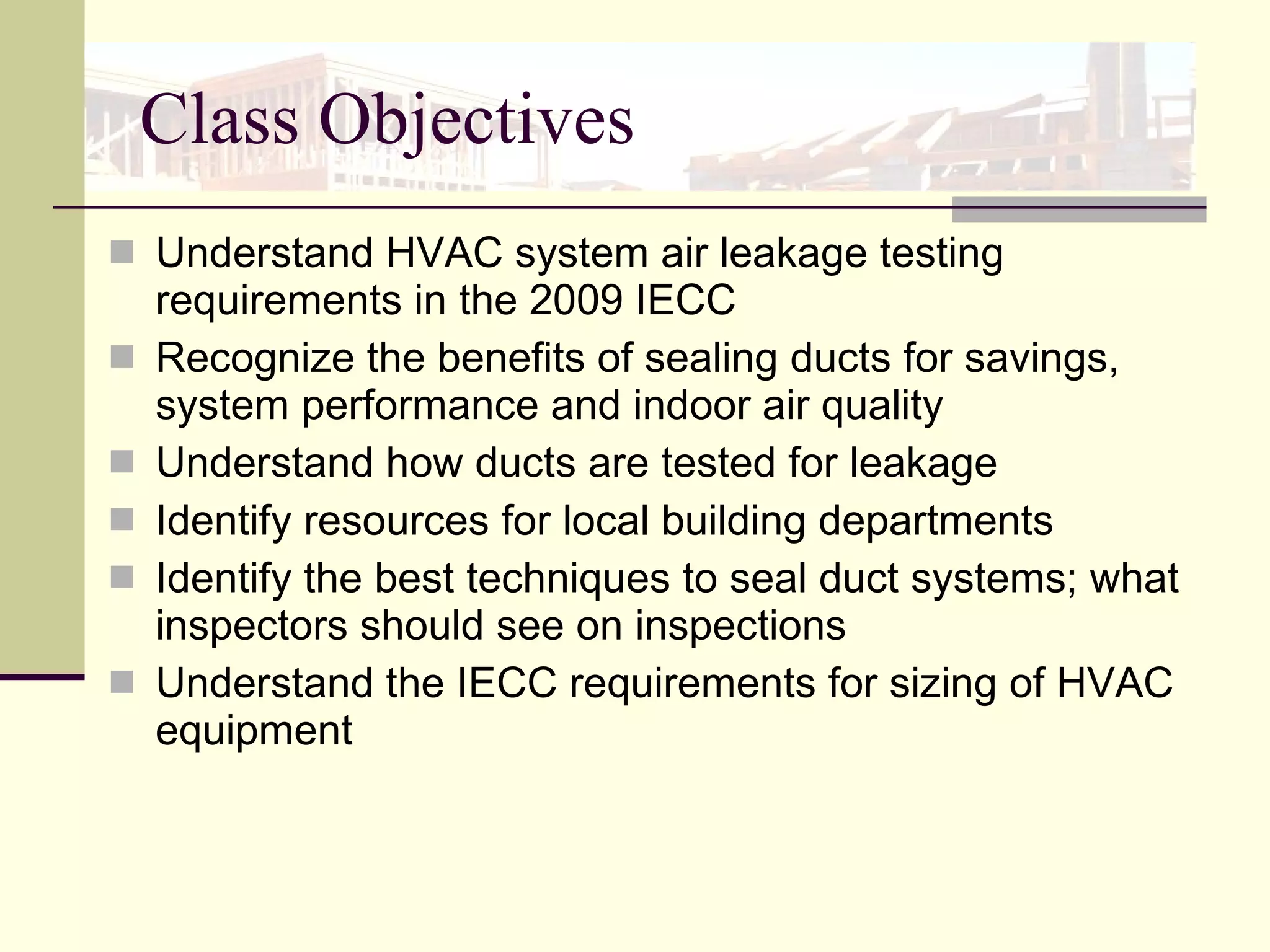
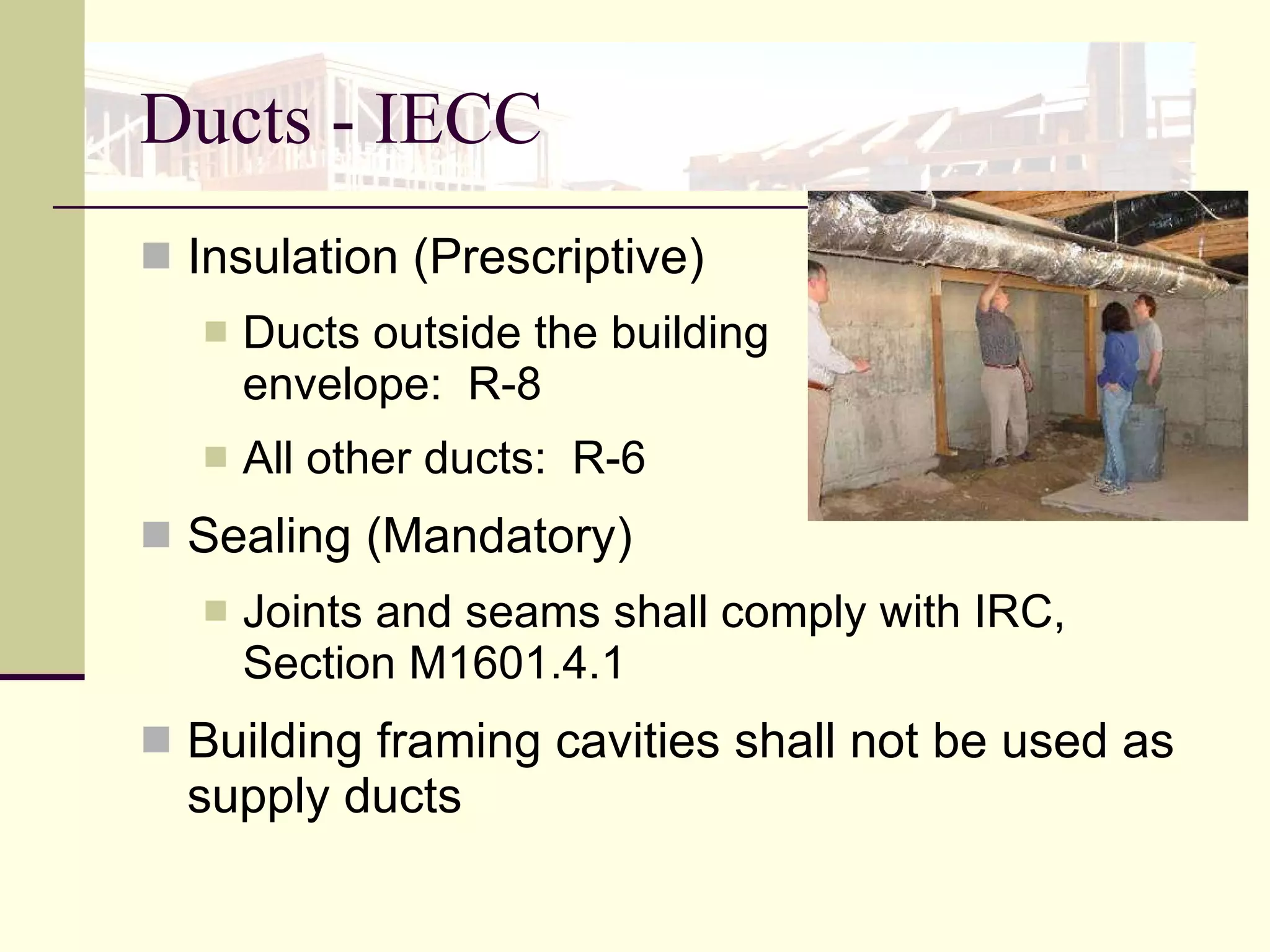
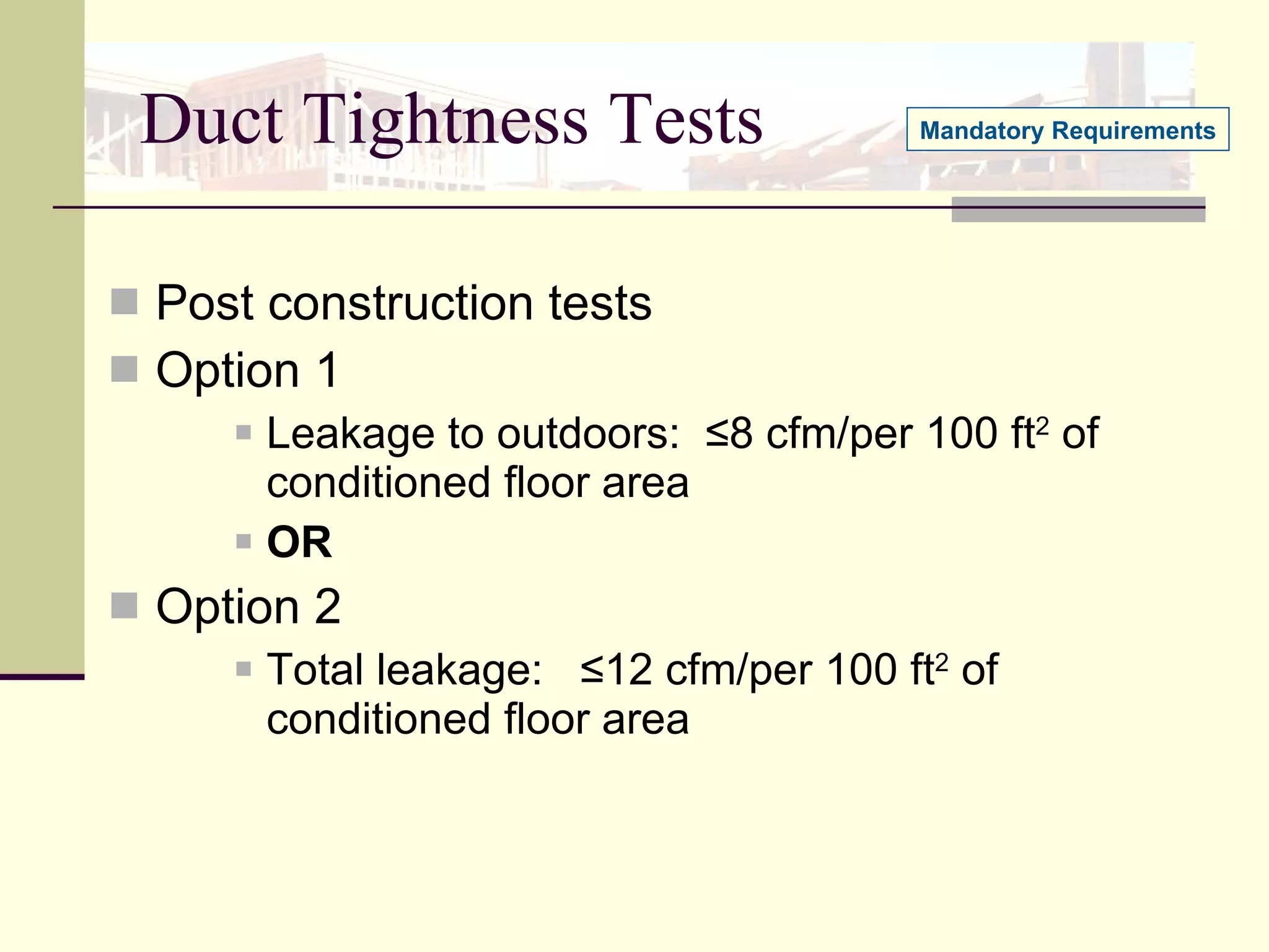

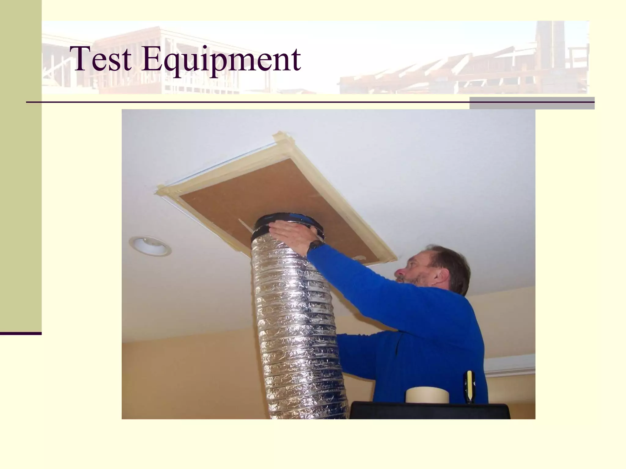
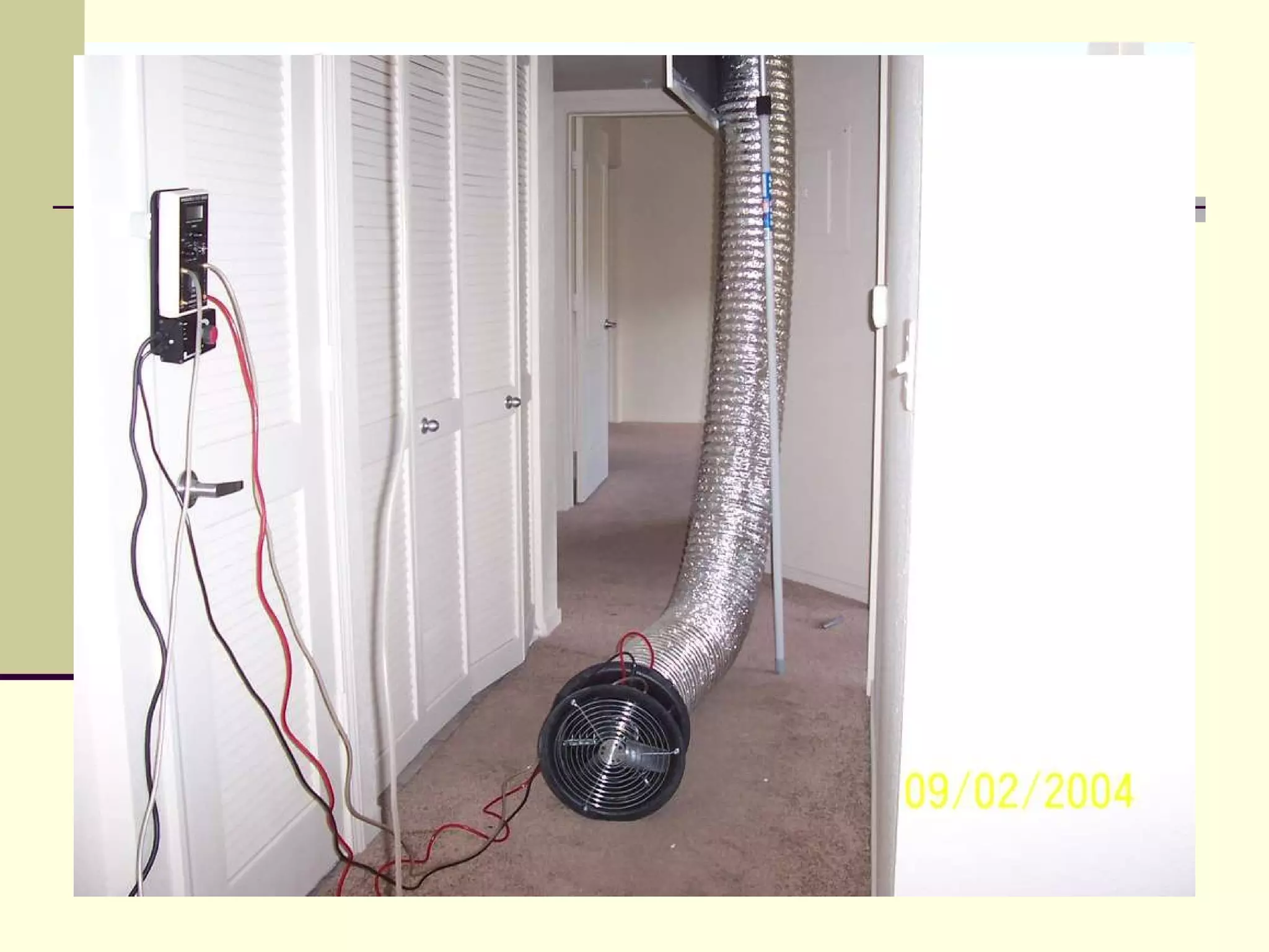

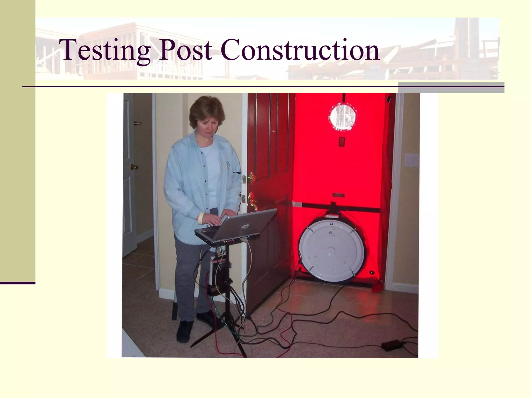

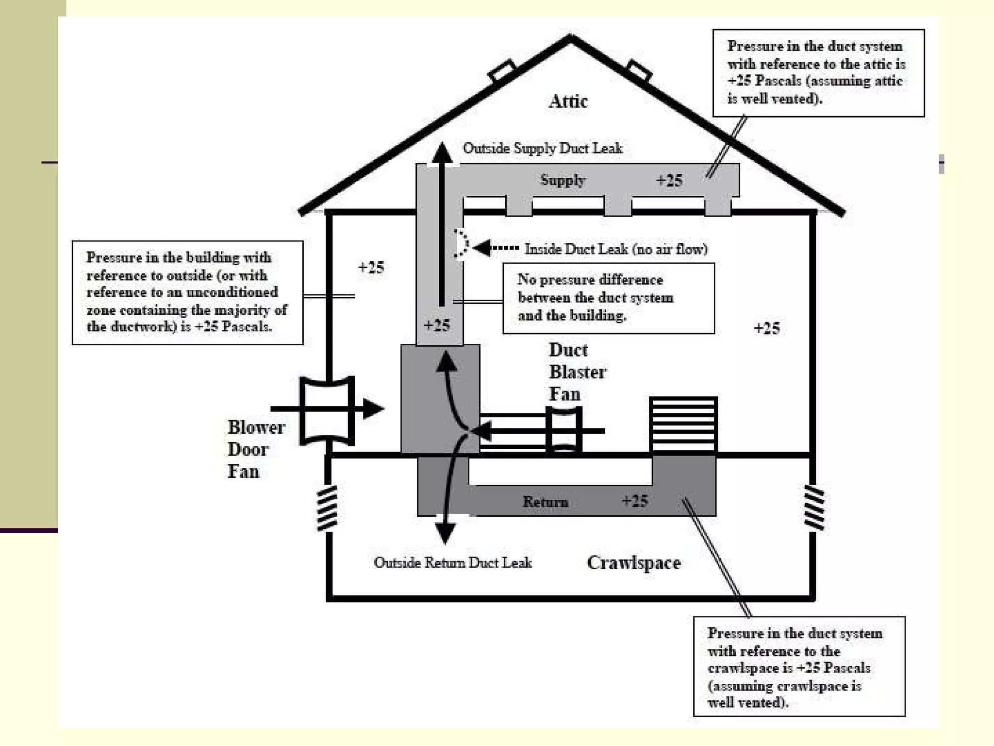

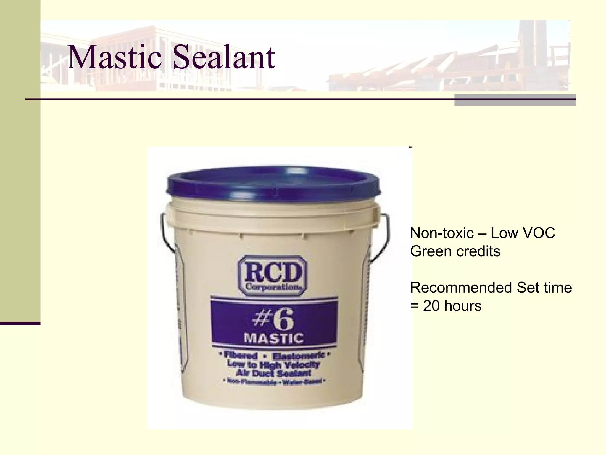
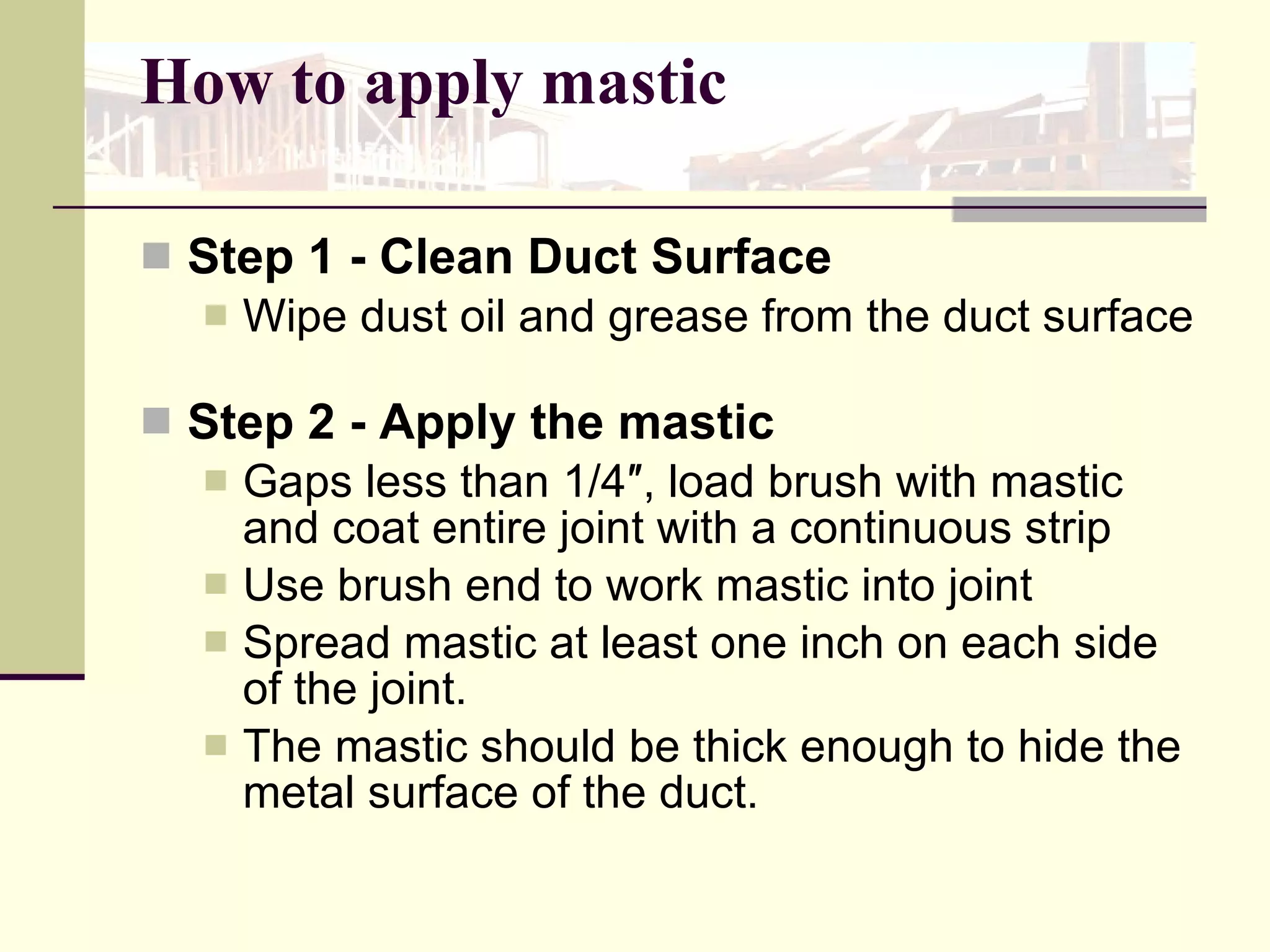
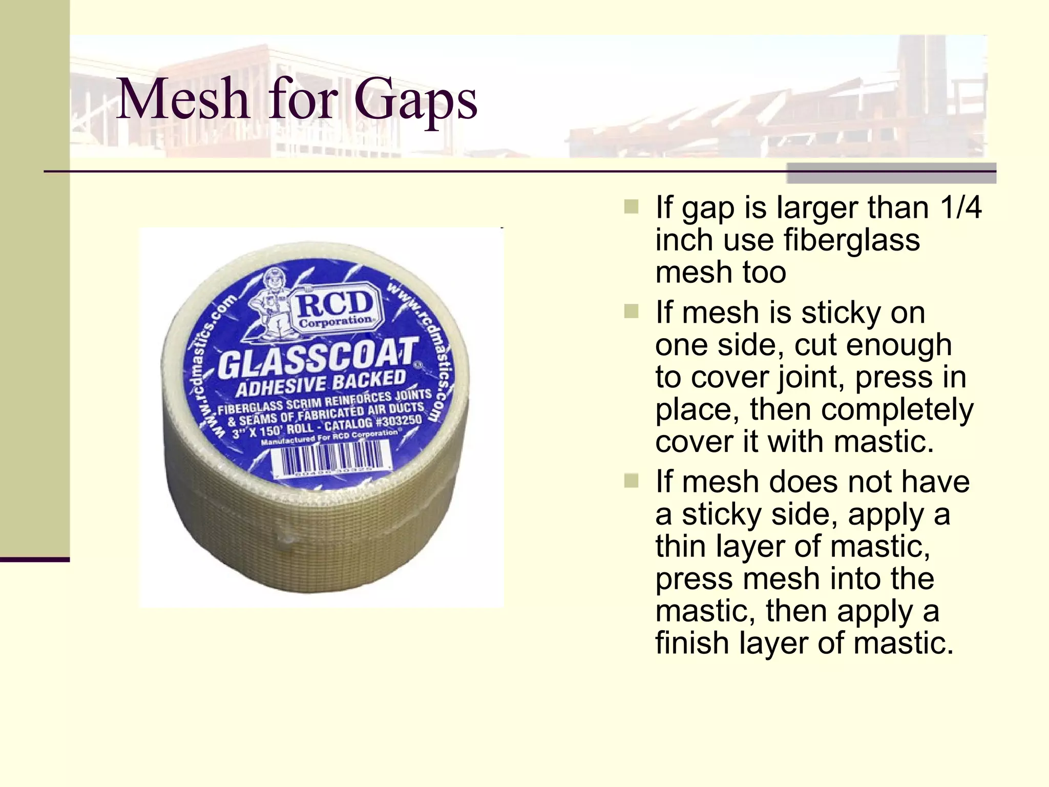


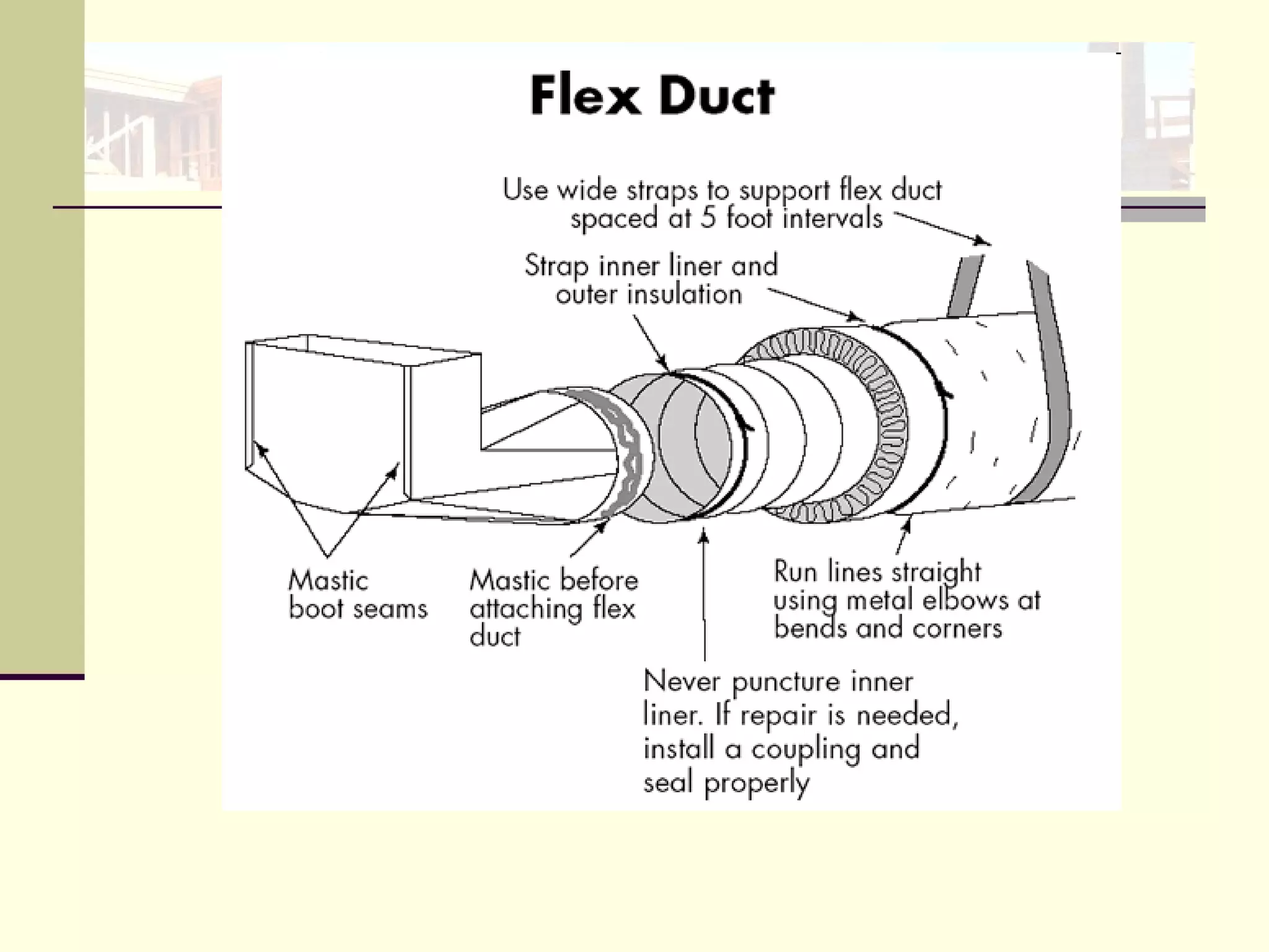
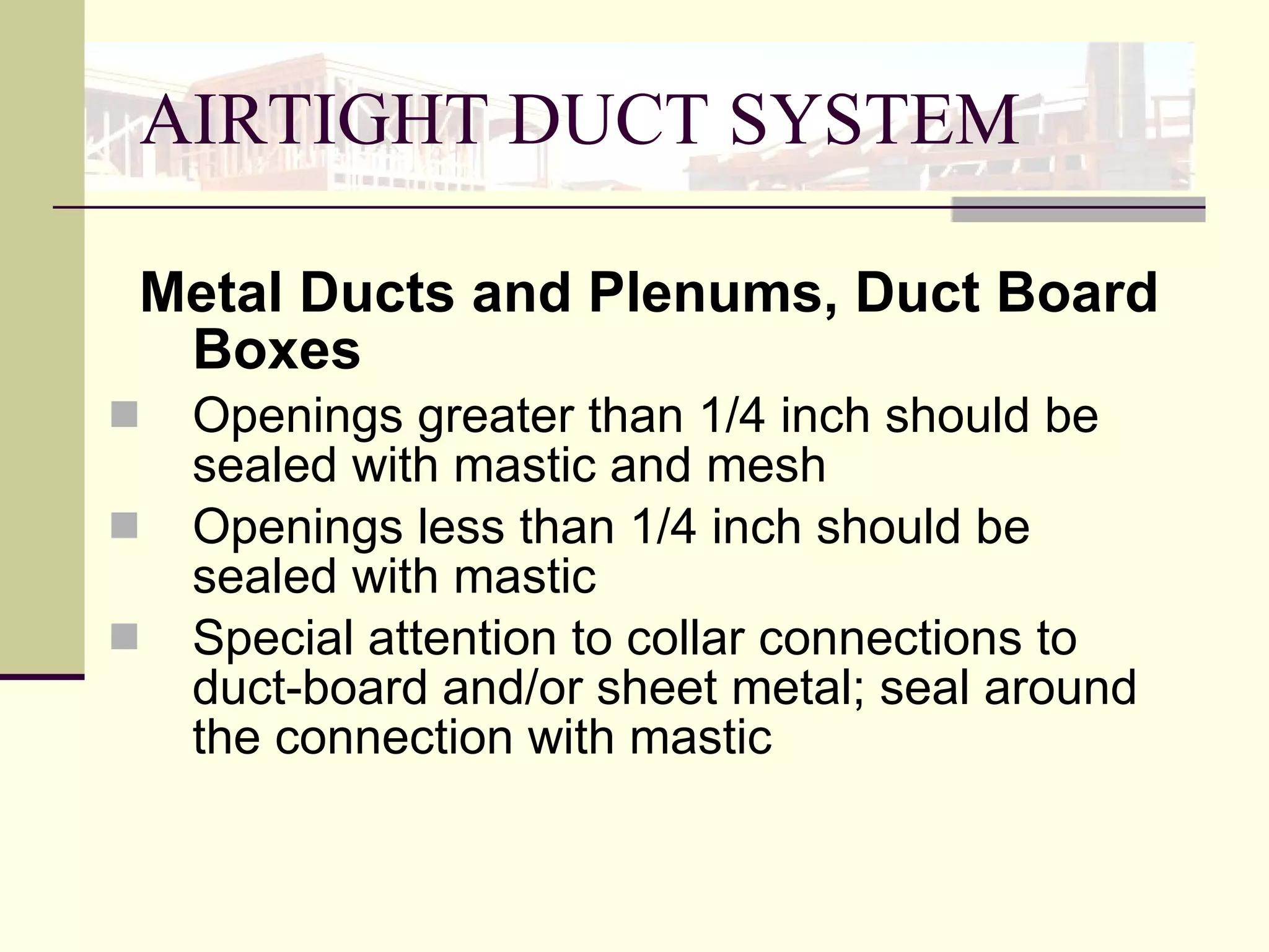

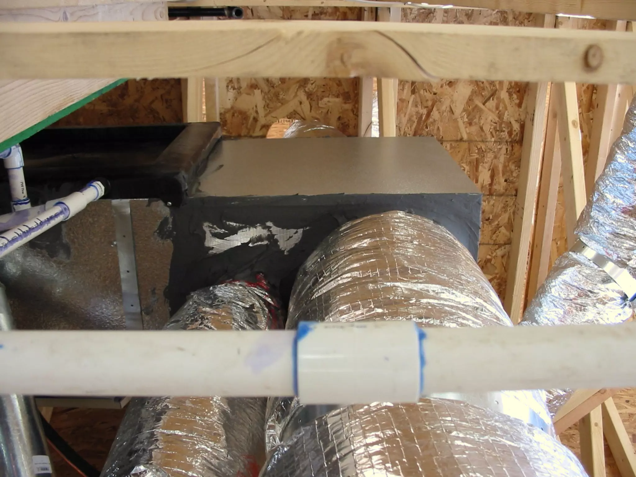

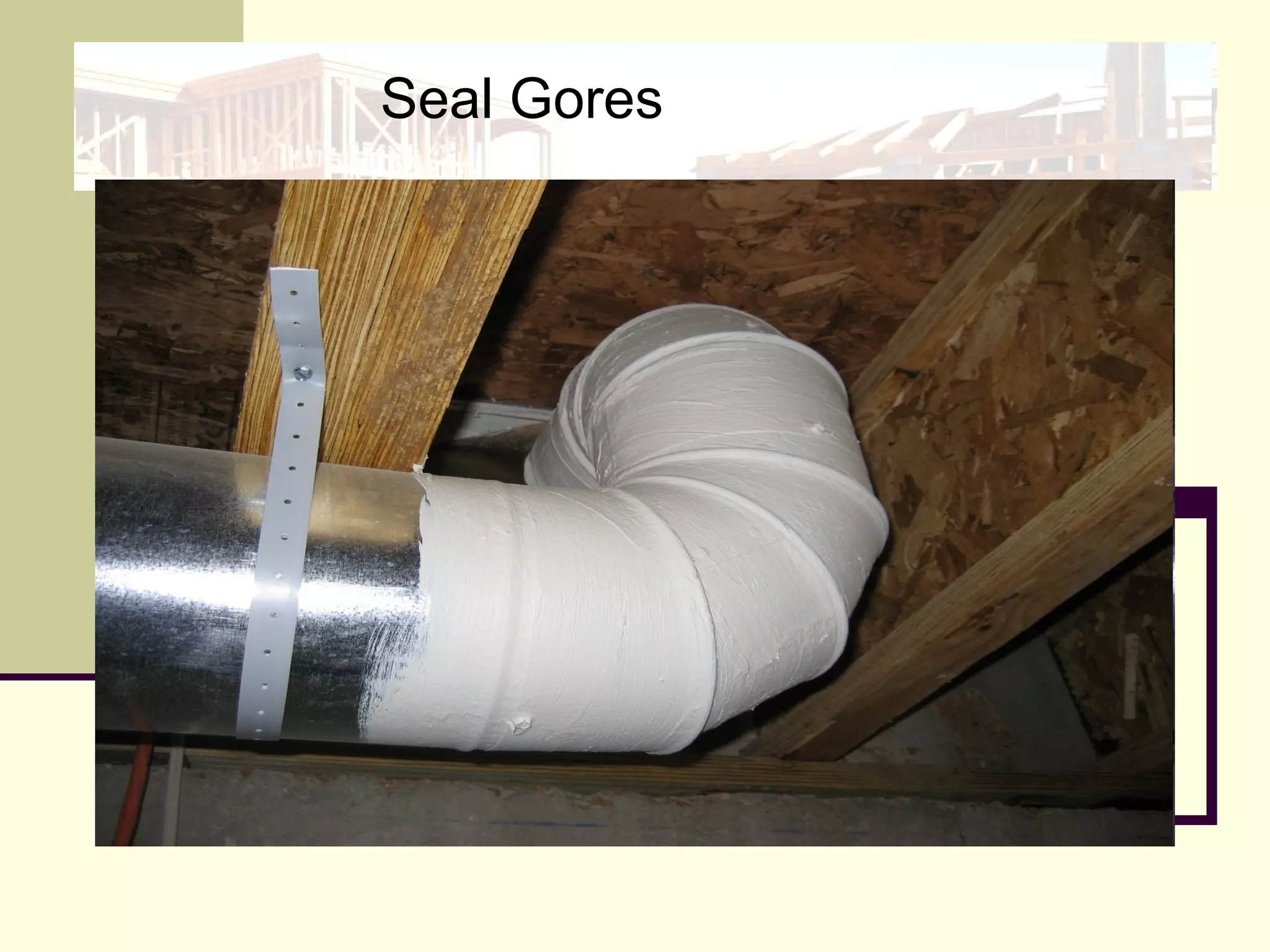

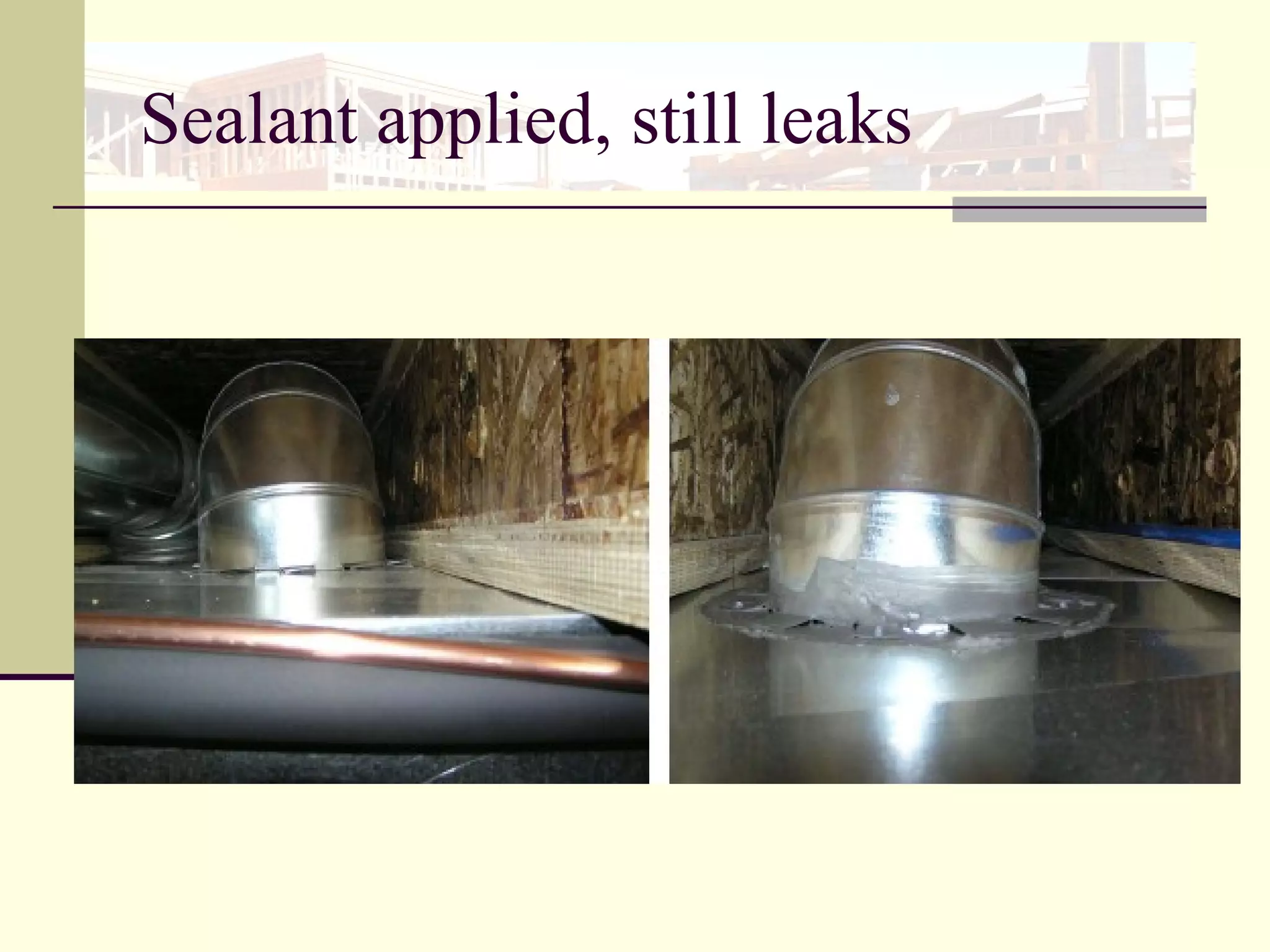

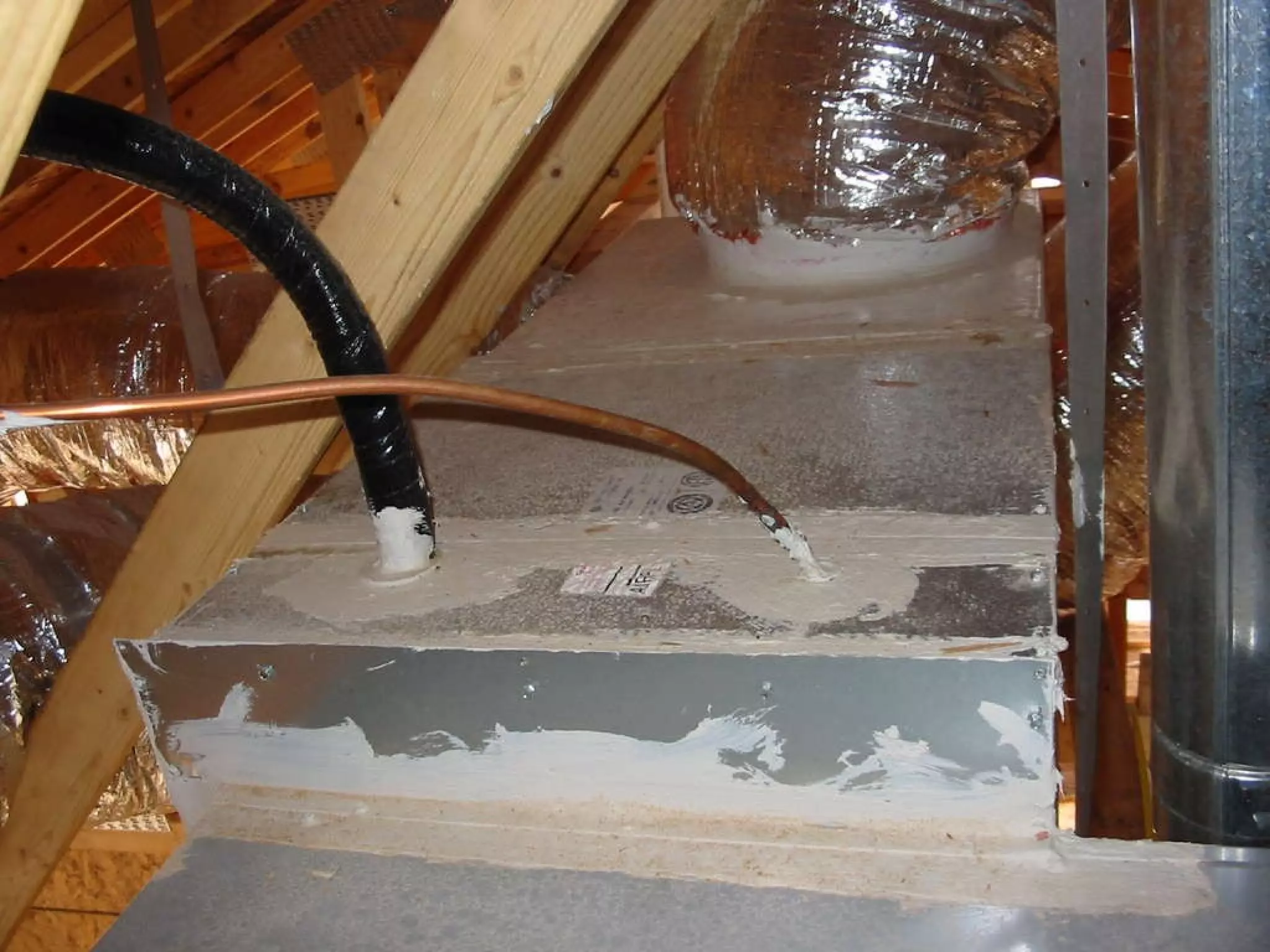
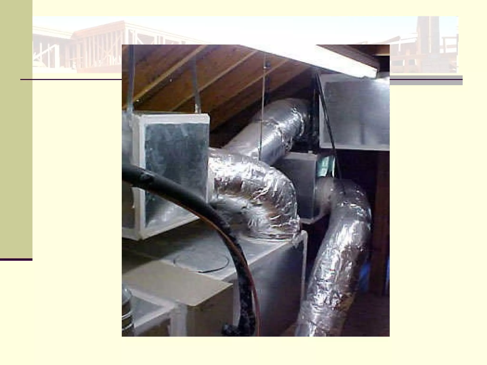
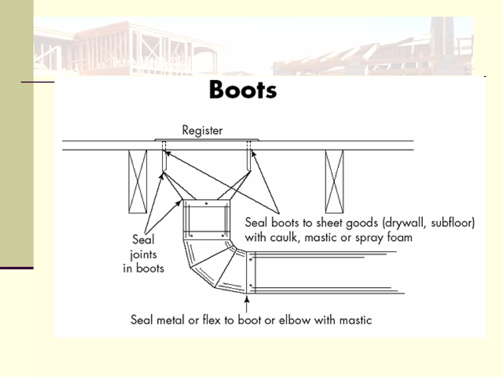

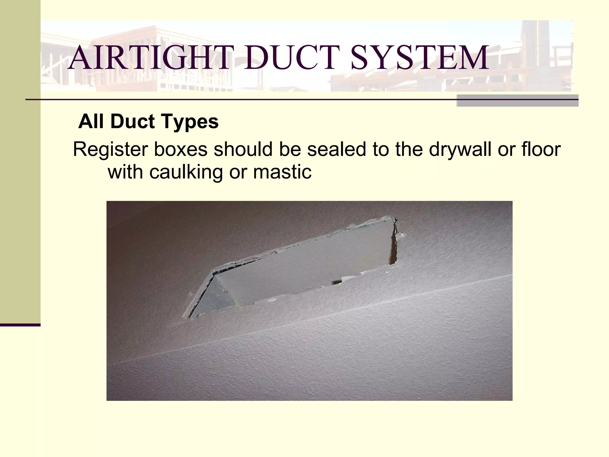


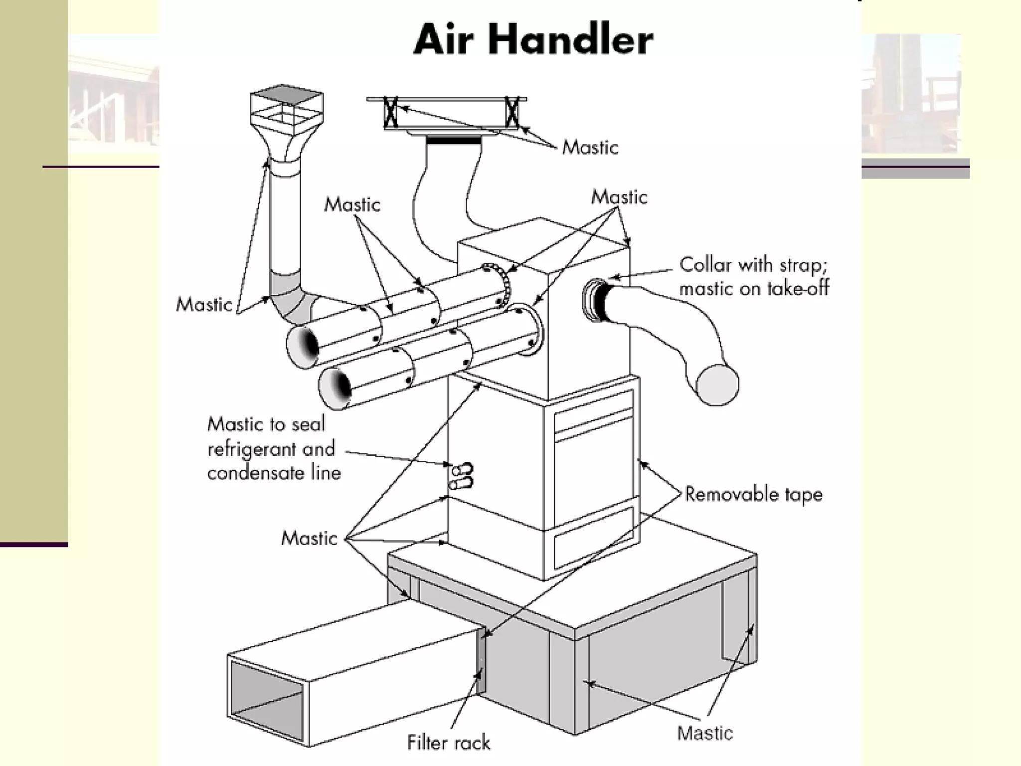

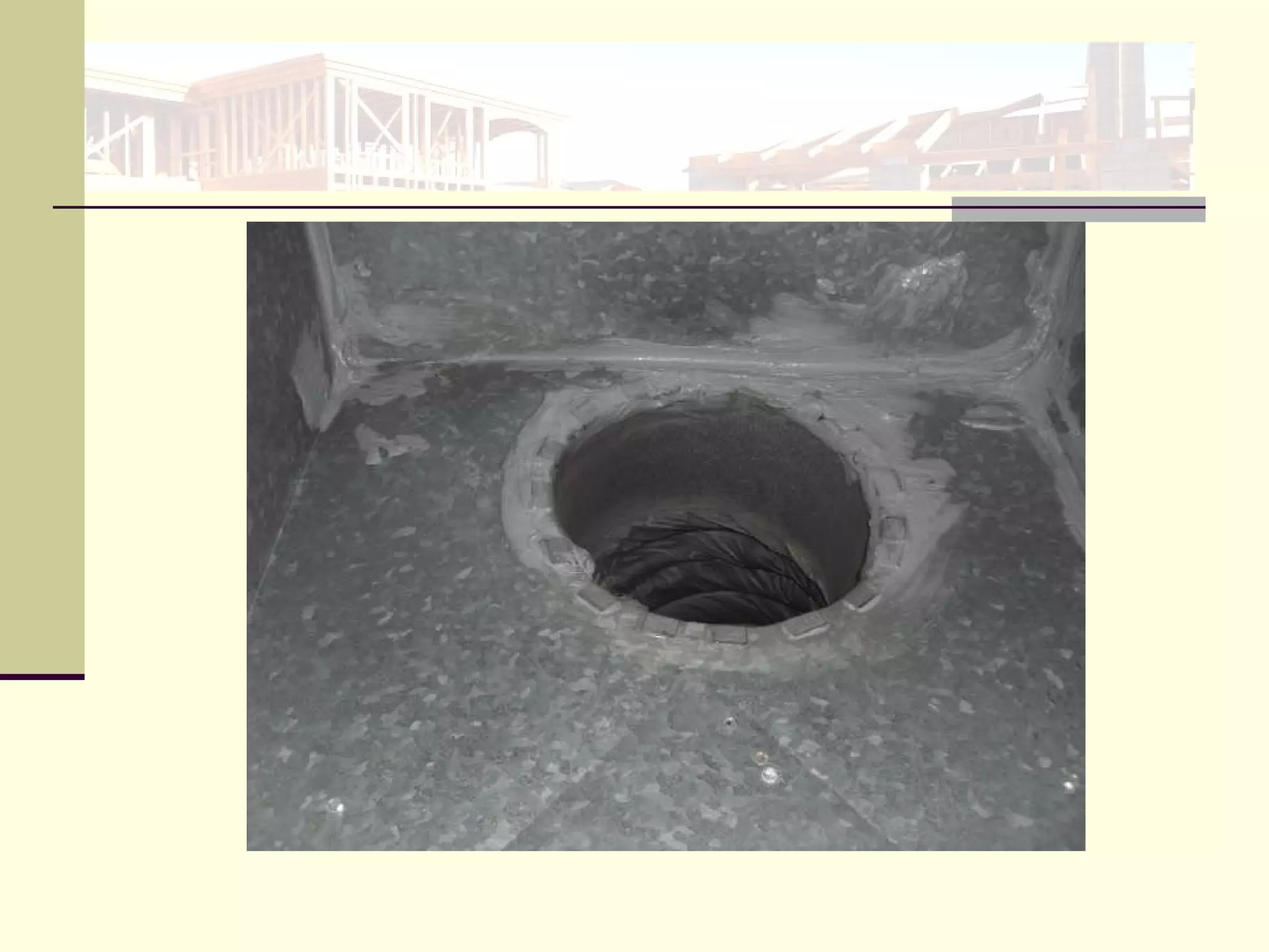


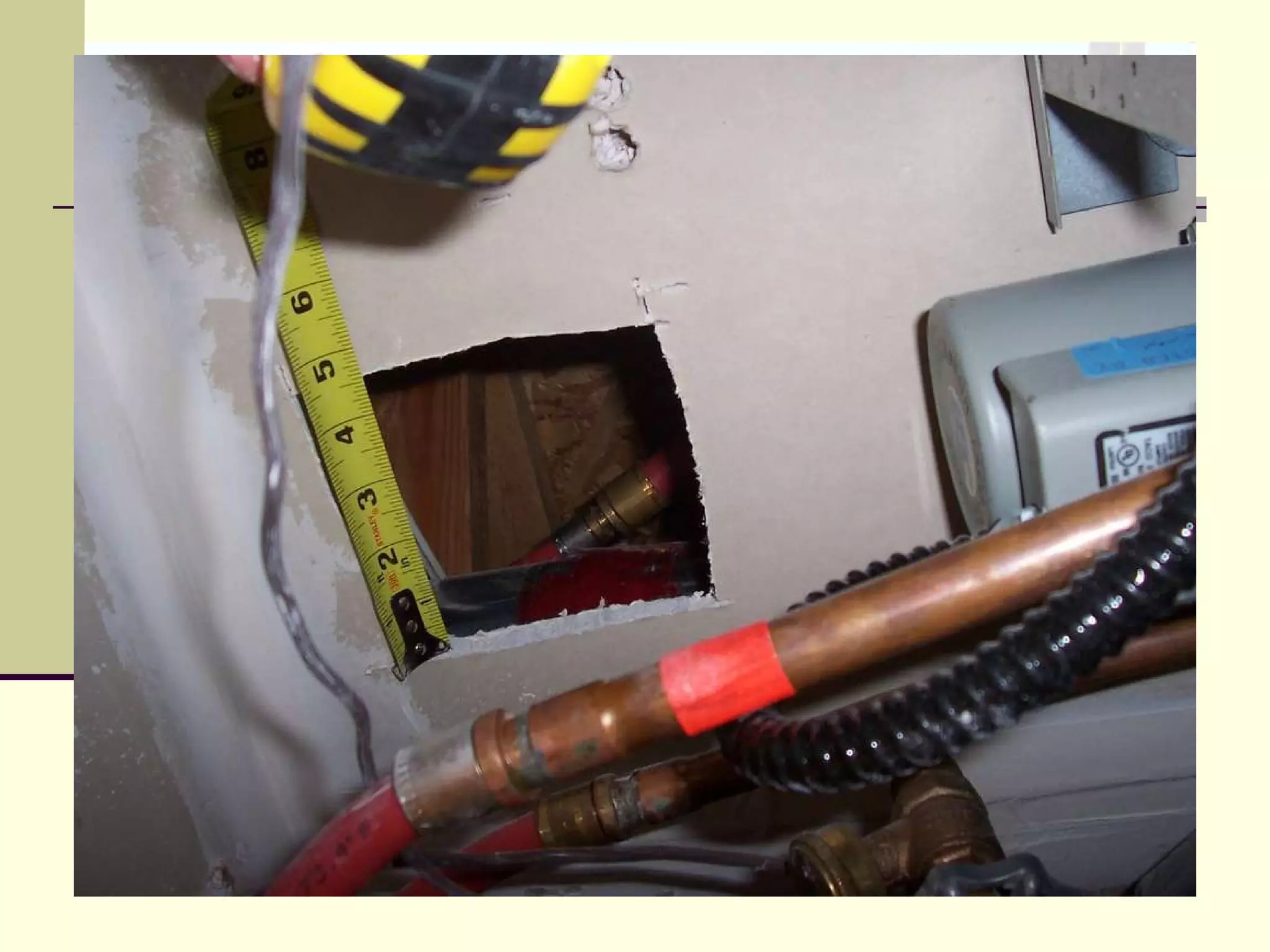
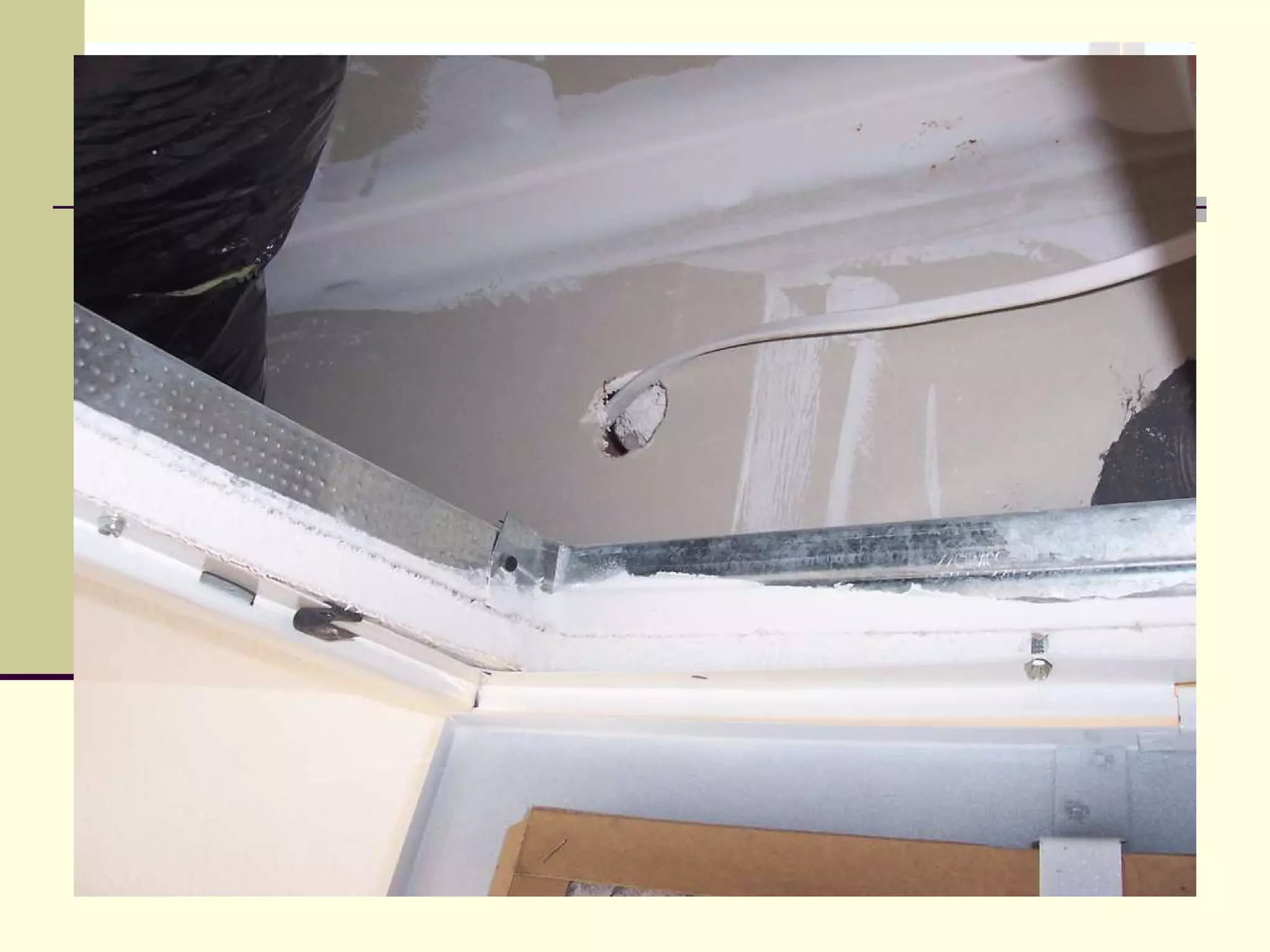

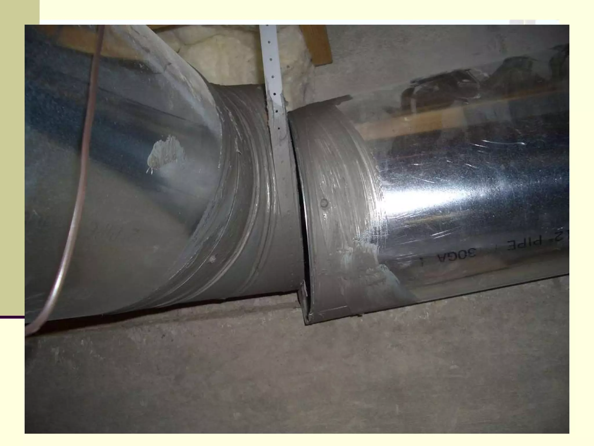
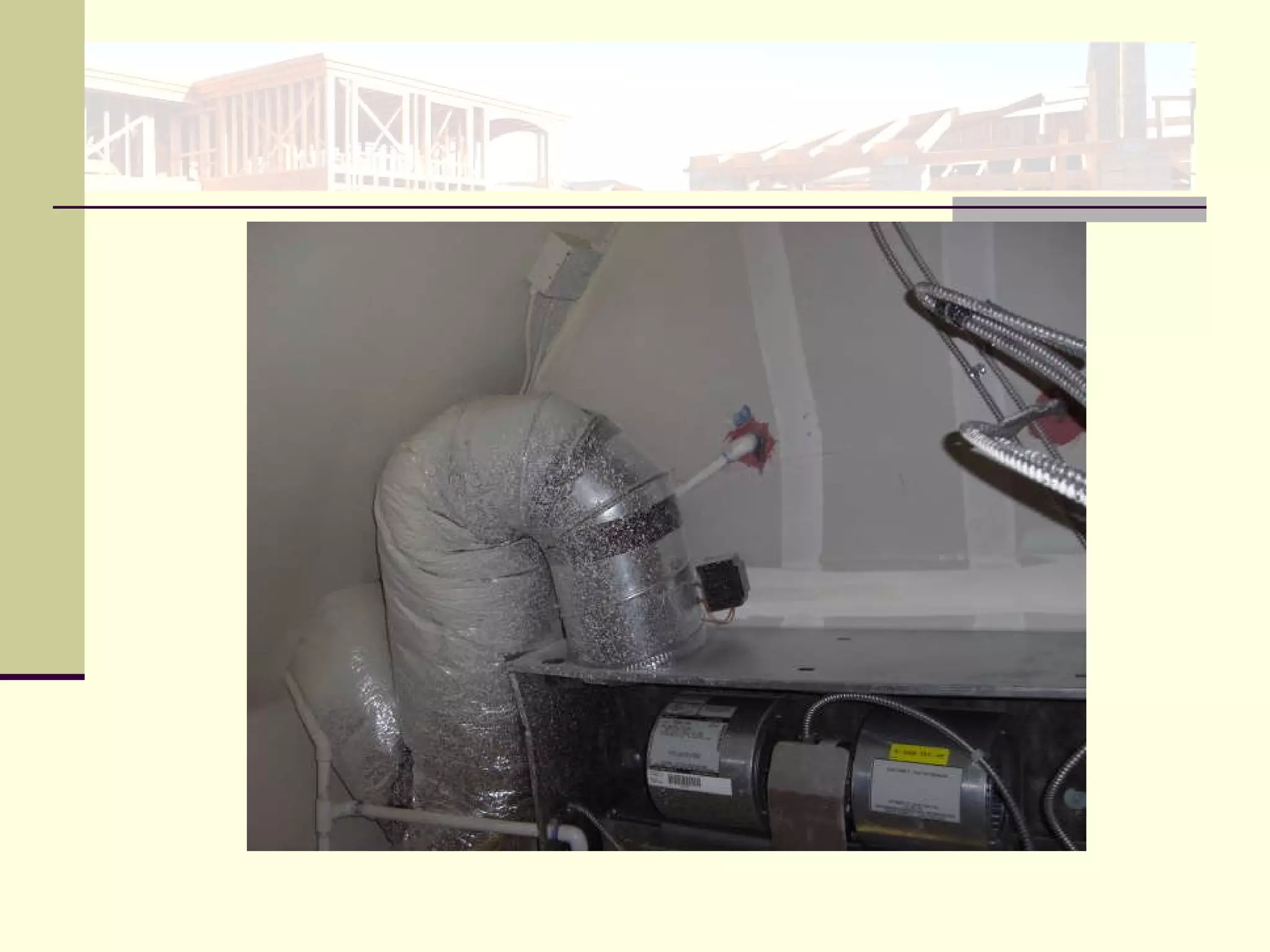


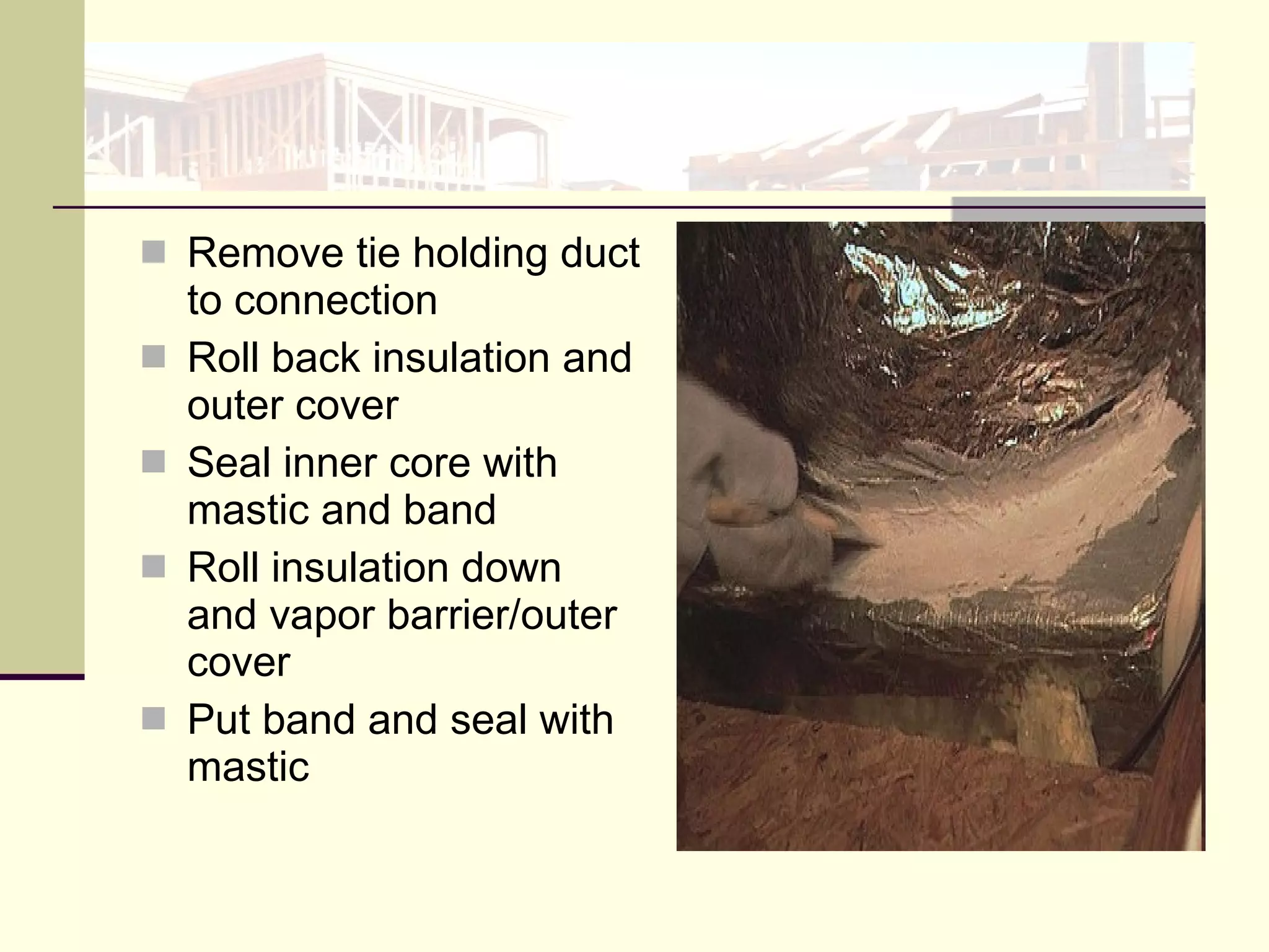
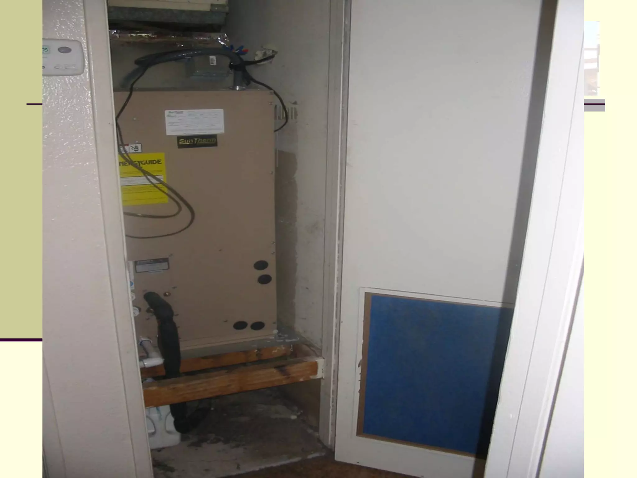

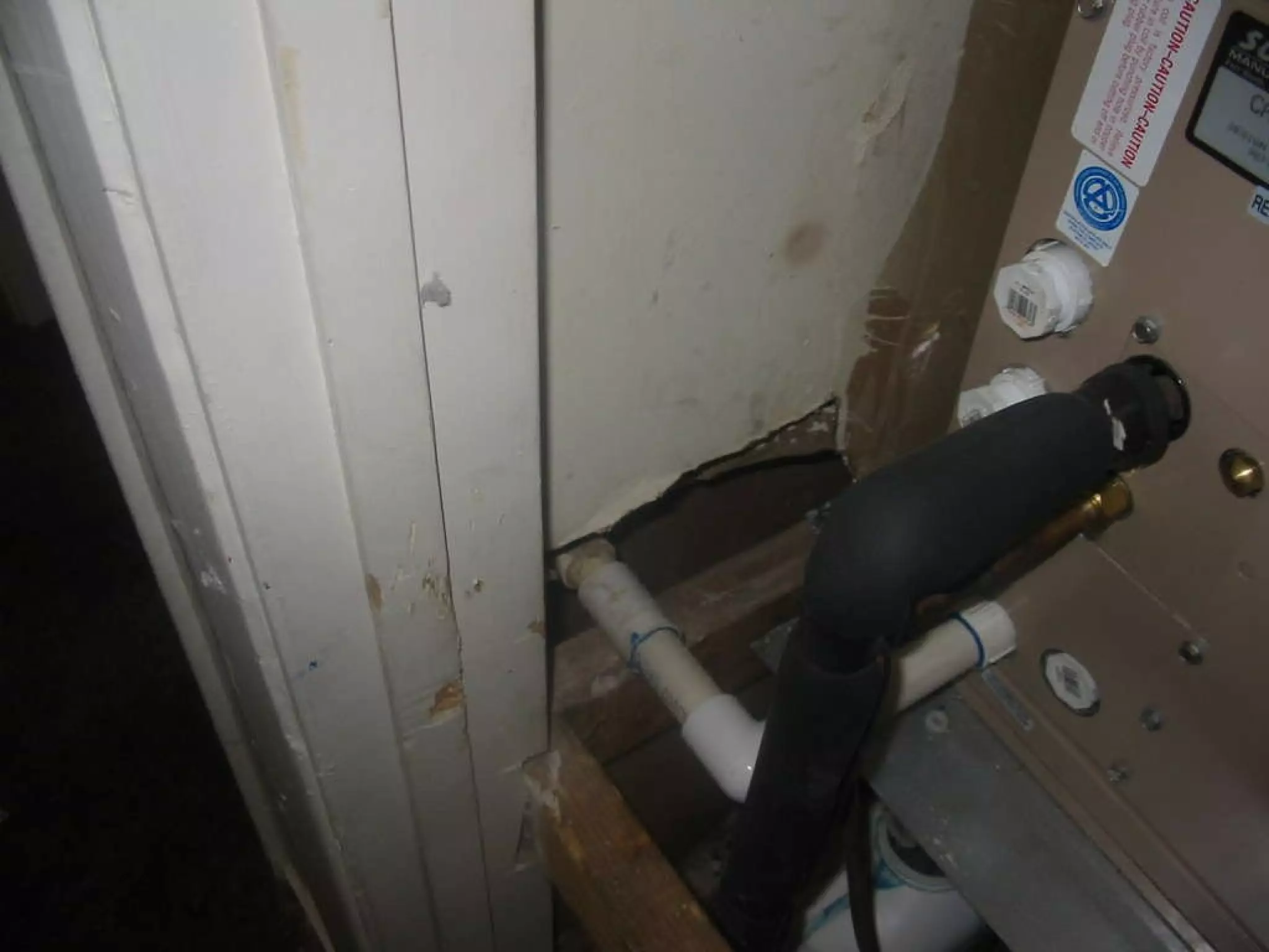

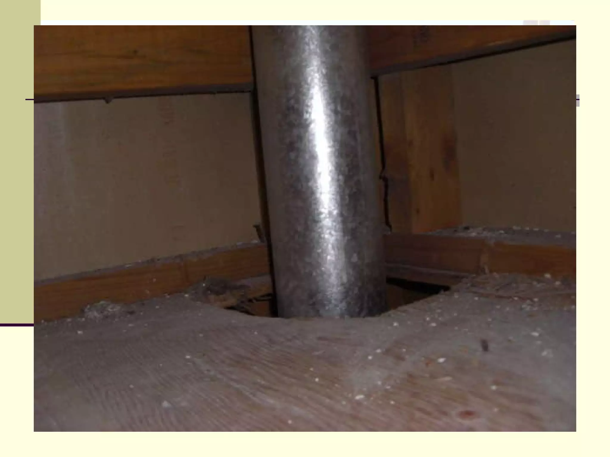

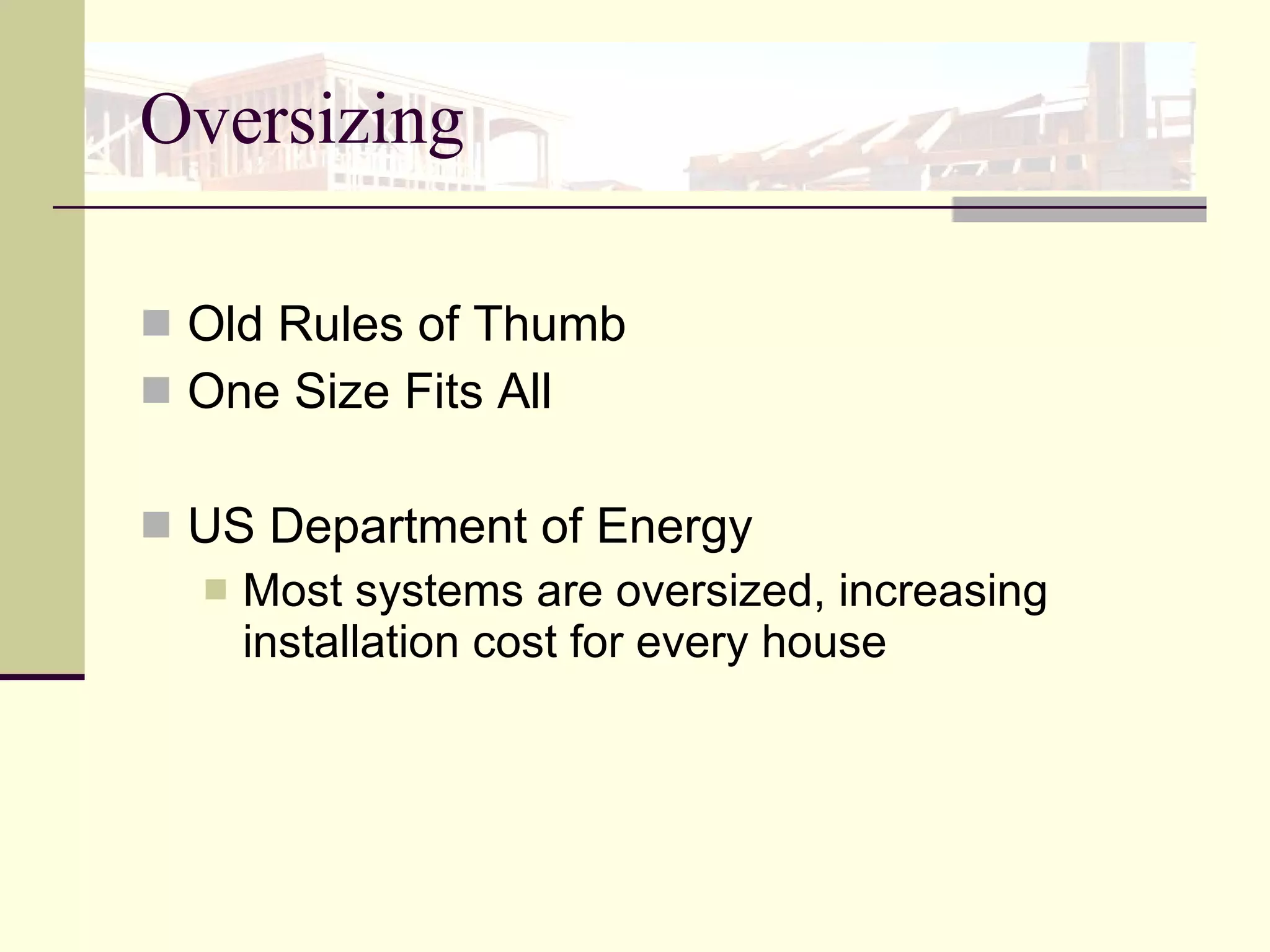
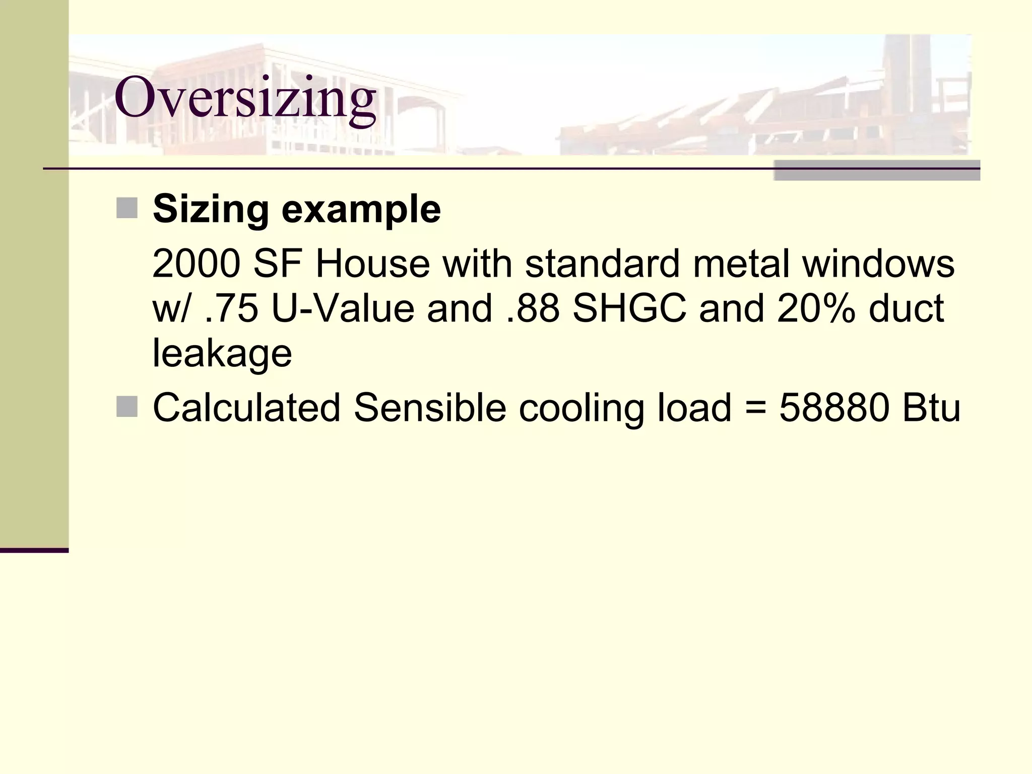

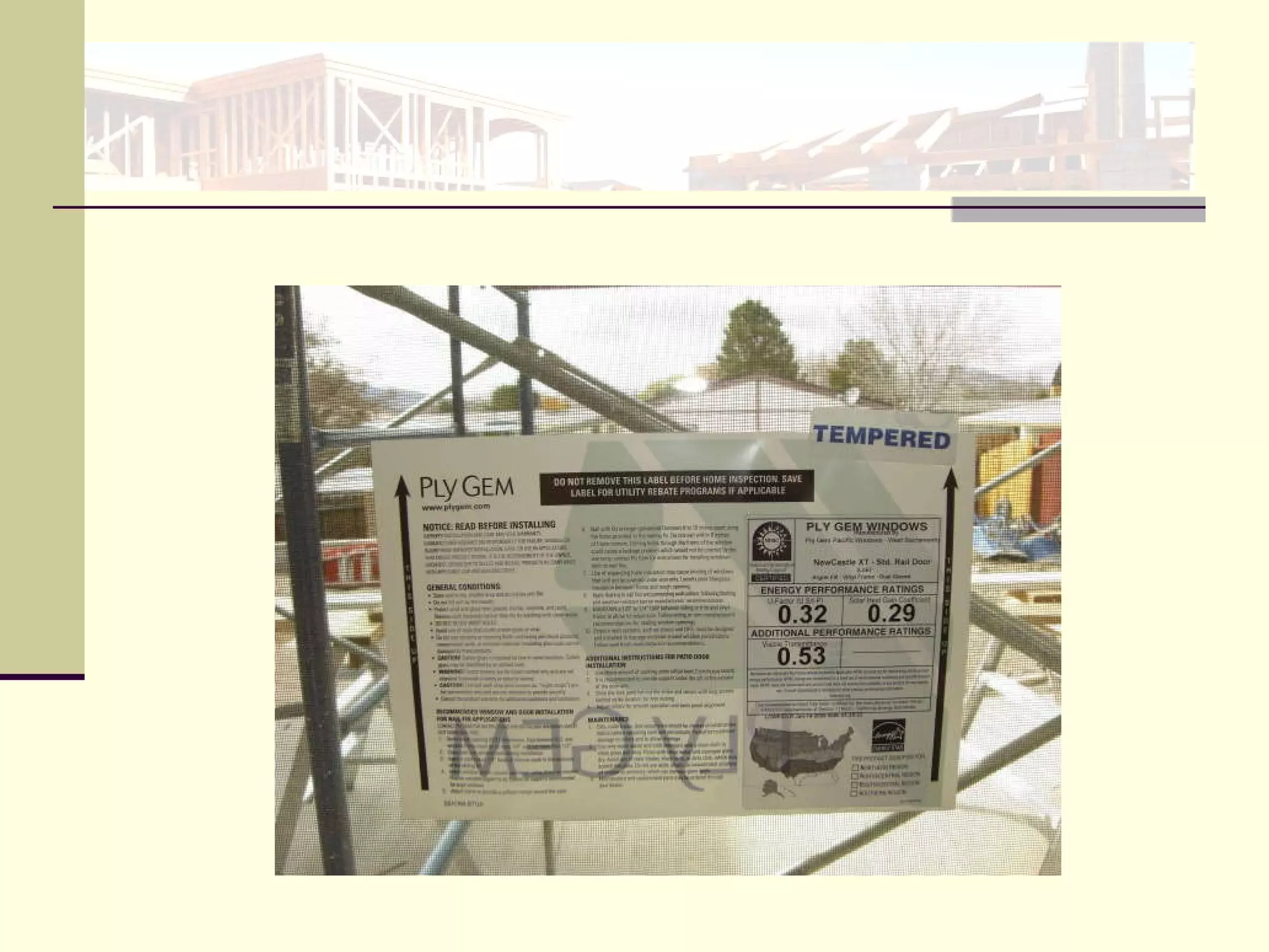


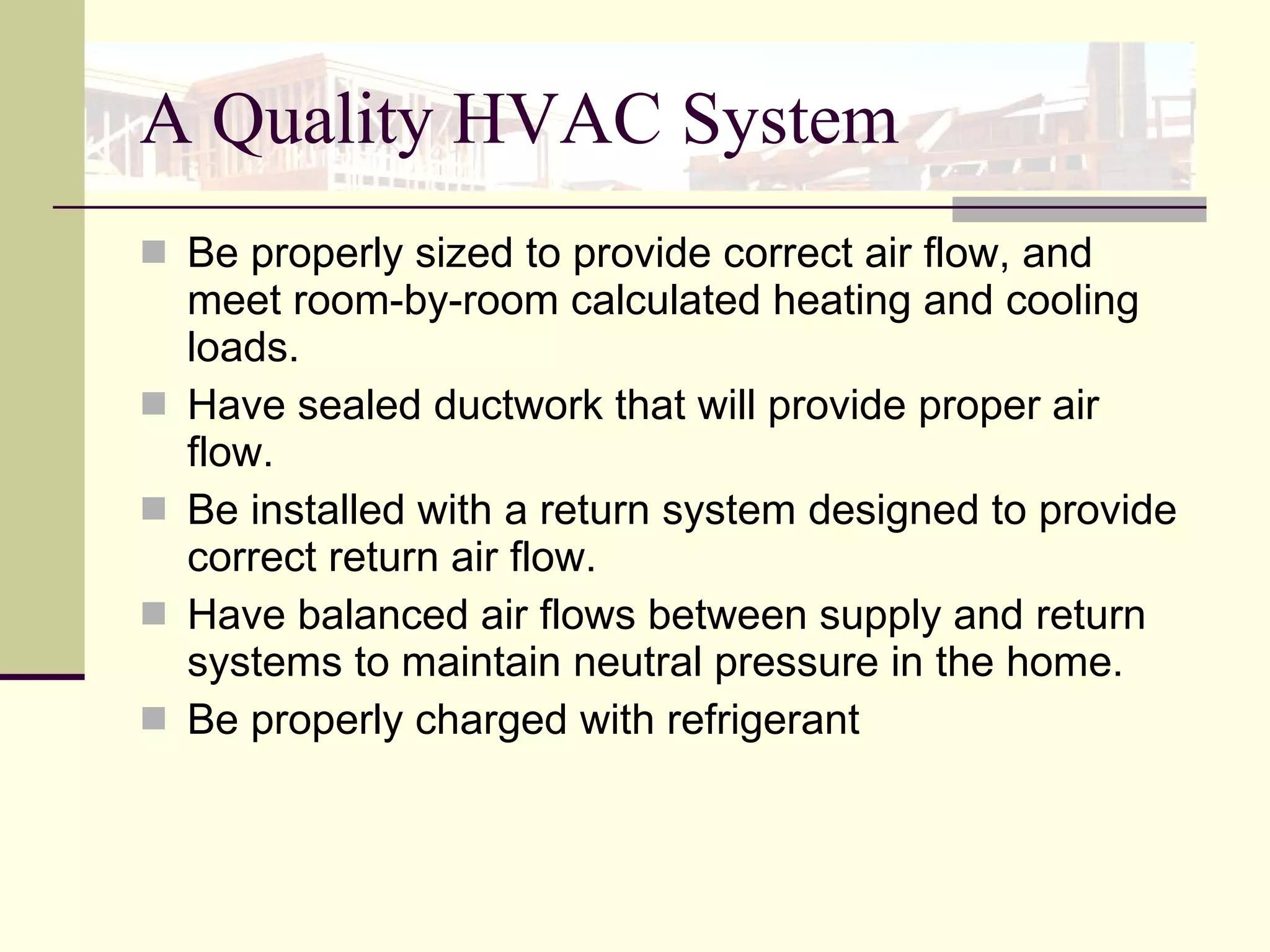
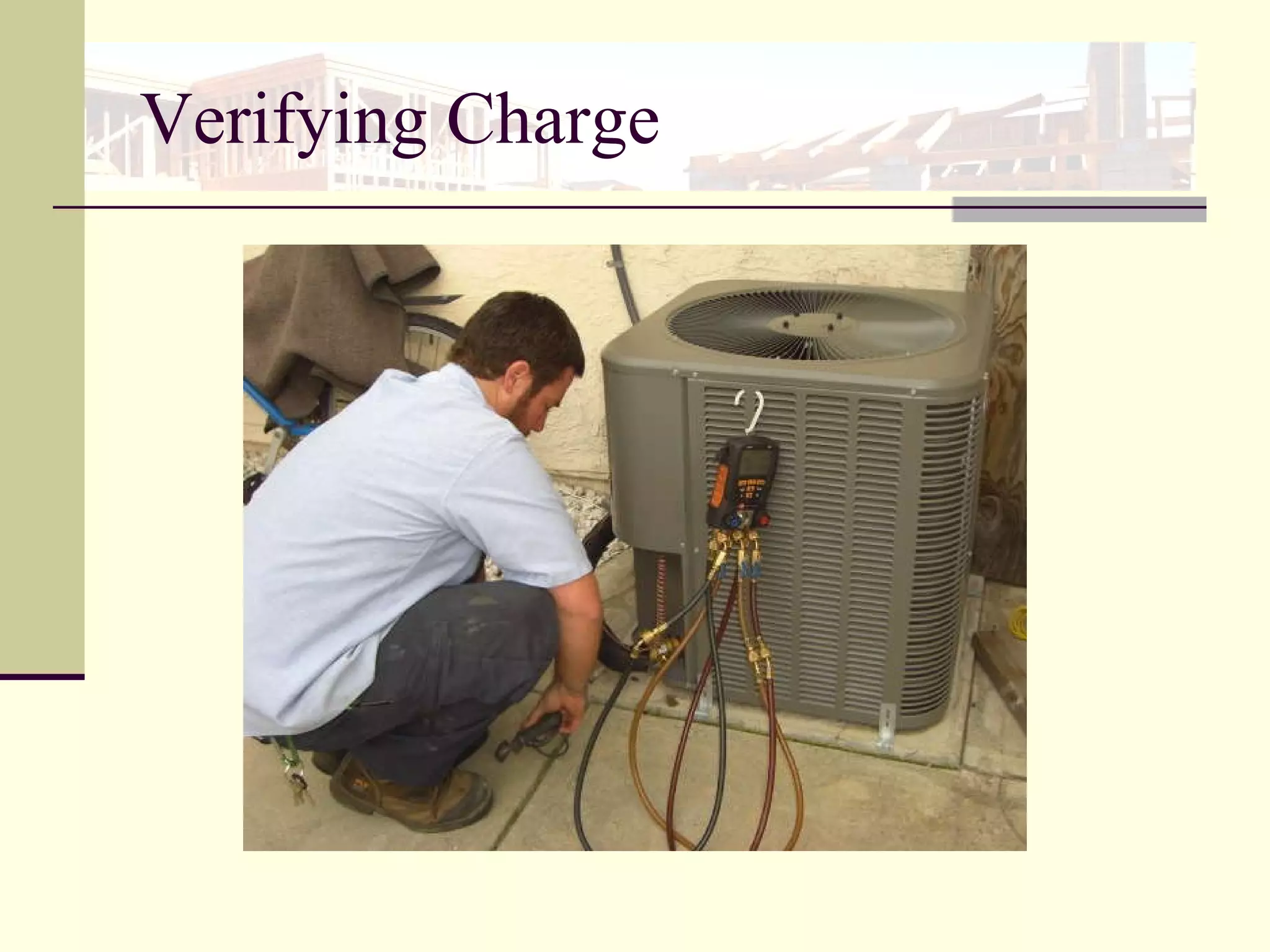


The document provides information about properly installing HVAC systems, including sealing ductwork to reduce energy losses and improve indoor air quality. It discusses code requirements for duct insulation, sealing, and leakage testing. Key points covered include the benefits of locating ducts within the thermal boundary, using mastic to seal ducts, proper sizing of HVAC equipment according to manual J load calculations, and sealing existing duct systems.


