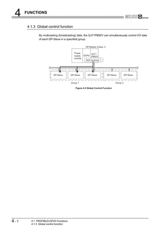
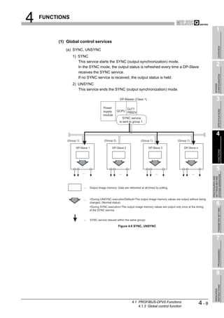
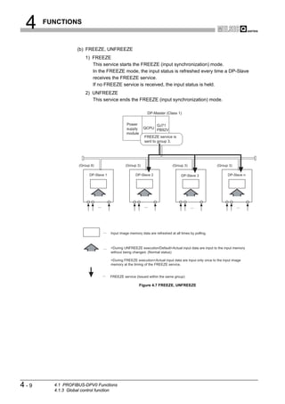
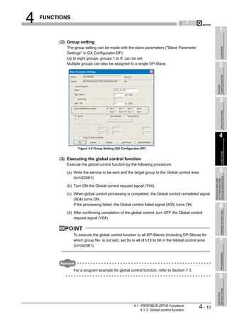
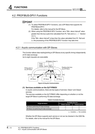
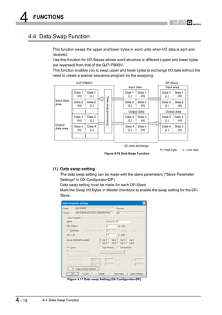
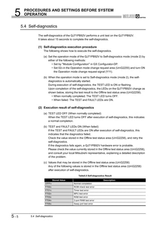
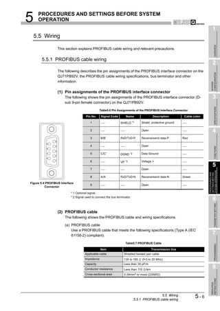
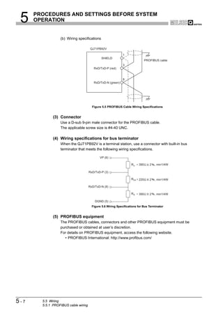
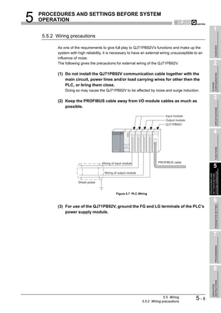
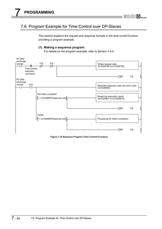
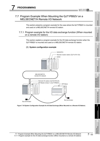
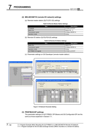
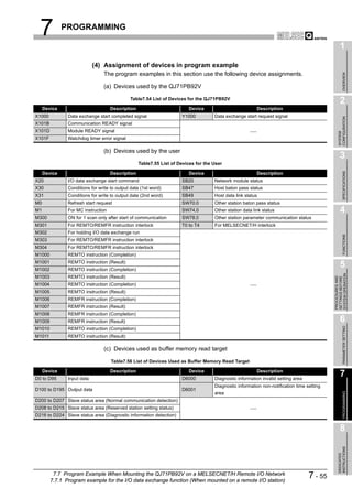
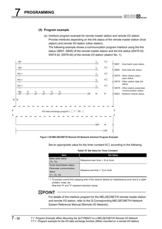
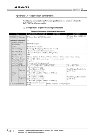
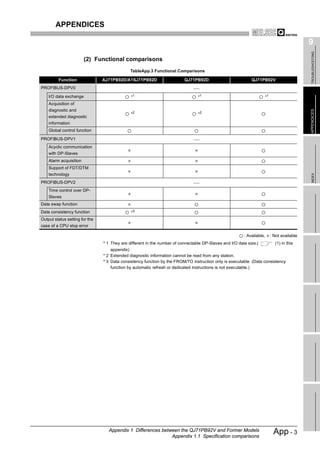
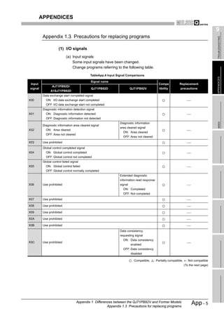
This document is the user's manual for the Mitsubishi QJ71PB92V PROFIBUS-DP Master Module. It contains safety precautions and design precautions related to installation and use of the module. Precautions include ensuring proper interlocking when communication errors occur, not outputting prohibited signals, and maintaining communication status depending on CPU error time output mode settings. The manual provides installation, wiring, and maintenance precautions and introduces compliance with EMC and low voltage directives.


![SAFETY PRECAUTIONS
(Read these precautions before using.)
Before using this product, please read this manual and the relevant manuals introduced in this manual
carefully and pay full attention to safety to handle the product correctly.
The instructions given in this manual are concerned with this product. For the safety instructions of the
programmable controller system, please read the user's manual of the CPU module used.
In this manual, the safety instructions are ranked as "DANGER" and "CAUTION".
DANGER Indicates that incorrect handling may cause hazardous conditions,
resulting in death or severe injury.
Indicates that incorrect handling may cause hazardous conditions,
CAUTION resulting in medium or slight personal injury or physical damage.
Note that the CAUTION level may lead to a serious consequence according to the circumstances.
Always follow the instructions of both levels because they are important to personal safety.
Please save this manual to make it accessible when required and always forward it to the end user.
[DESIGN PRECAUTIONS]
DANGER
When a communication error occurs on PROFIBUS-DP, the status of the faulty station is as shown
below.
Create an interlock circuit in the sequence program using the communication status information to
ensure the system operates safely (Input X1, buffer memory 5A20H to 5B19H (23072 to 23321)).
An erroneous output or malfunction may cause accidents.
(1) The QJ71PB92V holds the input data before the communication failure.
(2) When the QJ71PB92V has gone down, the output status of each DP-Slave is dependent on the
QJ71PB92V parameter setting on GX Configurator-DP.
(3) When a DP-Slave has gone down, the output status of the other DP-Slaves is dependent on the
QJ71PB92V parameter setting on GX Configurator-DP.
Do not output the "use prohibited" signal as the output signal to an intelligent function module from
the PLC CPU.
Wiring data into the "system area" or outputting a signal for "use prohibited" may cause system
malfunciton in the PLC.
A-1](https://image.slidesharecdn.com/qj71pb92v-091101233248-phpapp01/85/Qj71-Pb92-V-3-320.jpg)
![[DESIGN PRECAUTIONS]
DANGER
When a stop error has occurred on a CPU module, the communication status varies depending on
the error time output mode setting of GX Developer as shown below.
(1) When "Error time output mode" is set to "Hold".
(a) Communications with DP-Slaves are continued.
(b) Input data received from DP-Slaves are updated into the buffer memory of the QJ71PB92V.
(c) For the output data sent from the QJ71PB92V to DP-Slaves, the values at the time of the
CPU module stop error are held.
(2) When "Error time output mode" is set to "Clear"
(a) Communications with DP-Slaves are interrupted, and output data are not sent.
(b) Input data received from DP-Slaves are held in the buffer memory of the QJ71PB92V.
CAUTION
Do not install PROFIBUS cables together with the main circuit or power lines or bring them close to
each other.
Keep a distance of 100mm (3.9inch) or more between them.
Failure to do so may cause malfunctions due to noise.
[INSTALLATION PRECAUTIONS]
CAUTION
Use the PLC under the environment specified in the user’s manual of the CPU module to be used.
Otherwise, it may cause electric shocks, fires, malfunctions, product deterioration or damage.
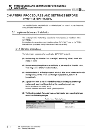
While pressing the installation lever located at the bottom of the module, insert the module fixing
projection into the fixing hole in the base unit to mount the module.
Incorrect mounting may cause malfunctions, a failure or a drop of the module.
In an environment of frequent vibrations, secure the module with the screw.
Tighten the screw within the specified torque range.
If the screw is too loose, it may cause a drop of the module, a short circuit or malfunctions.
Overtightening may damage the screw and/or the module, resulting in a drop of the module, a short
circuit or malfunctions.
Be sure to shut off all phases of the external power supply used by the system before mounting or
removing the module.
Failure to do so may damage the module.
A-2](https://image.slidesharecdn.com/qj71pb92v-091101233248-phpapp01/85/Qj71-Pb92-V-4-320.jpg)
![[INSTALLATION PRECAUTIONS]
CAUTION
Do not directly touch the conductive part or electronic components of the module.
Doing so may cause malfunctions or a failure of the module.
[WIRING PRECAUTIONS]
DANGER
Be sure to shut off all phases of the external power supply used by the system before wiring
PROFIBUS cables.
Failure to do so may result in failure or malfunctions of the module.
CAUTION
Carefully prevent foreign matter such as dust or wire chips from entering the module.
Failure to do so may cause a fire, failure or malfunctions.
Be sure to place the PROFIBUS cables in a duct or clamp them.
If not, dangling cables may be shifted or inadvertently pulled, resulting in damages to the module or
cables or malfunctions due to poor cable contact.
When disconnecting the PROFIBUS cable, do not pull it by holding the cable part.
Be sure to hold its connector which is plugged into the module.
Pulling the cable with it connected to the module may damage the module and/or cable, or cause
malfunctions due to poor contact of the cable.
A protective film is attached onto the module top to prevent foreign matter such as wire chips from
entering the module when wiring.
Do not remove the film during wiring.
Remove it for heat dissipation before system operation.
A-3](https://image.slidesharecdn.com/qj71pb92v-091101233248-phpapp01/85/Qj71-Pb92-V-5-320.jpg)
![[STARTING AND MAINTENANCE PRECAUTIONS]
DANGER
Before cleaning, be sure to shut off all phases of the external power supply used by the system.
Failure to do so may cause electrical shocks.
CAUTION
Do not disassemble or modify the module.
Doing so may cause failure, malfunctions, personal injuries and/or a fire.
Be sure to shut off all phases of the external power supply before mounting or removing the module.
Failure to do so may result in failure or malfunctions of the module.
Module installation to or removal from the base unit is limited to 50 times after the first use of the
product. (IEC 61131-2 compliant)
Exceeding 50 times may cause malfunctions.
Before handling modules, touch a grounded metal object to discharge the static electricity from the
human body.
Not doing so may cause failure or malfunctions of the module.
[DISPOSAL PRECAUTIONS]
CAUTION
When disposing of this product, treat is as an industrial waste.
A-4](https://image.slidesharecdn.com/qj71pb92v-091101233248-phpapp01/85/Qj71-Pb92-V-6-320.jpg)

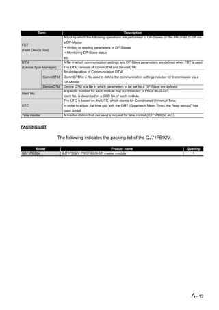
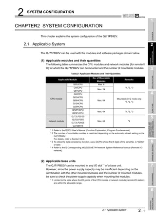
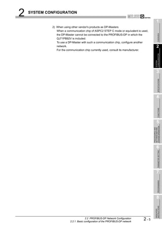
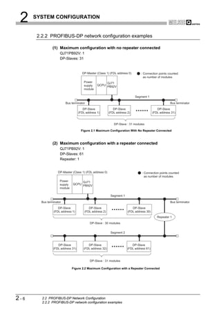
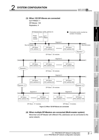
![2 SYSTEM CONFIGURATION
2.3 Checking the Function Version and Serial No.
This section explains how to check the function version and serial No. of the QJ71PB92V.
(1) Checking the "Rating plate" on the side of the module
The serial No. and function version of the module are printed in the SERIAL section of
the rating plate.
Serial No. (Upper 5 digits)
Function version
07091 B
Conformed standard
Figure 2.4 Rating Plate
(2) Checking through GX Developer
The following explains how to check the serial No. and function version of the module
through GX Developer.
The serial No. and function version are displayed on the "Product information list" or
"Module's Detailed Information" screen of GX Developer.
The procedure for checking the serial No. and function version on the "Product
information list" screen is shown below.
Start Procedure
[Diagnostics] [System monitor] [Product information list]
Figure 2.5 Product Information List
[Serial No., Ver.]
• The serial No. of the module is displayed in the "Serial No." column.
• The function version of the module is displayed in the "Ver." column.
2-8 2.3 Checking the Function Version and Serial No.](https://image.slidesharecdn.com/qj71pb92v-091101233248-phpapp01/85/Qj71-Pb92-V-26-320.jpg)
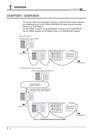
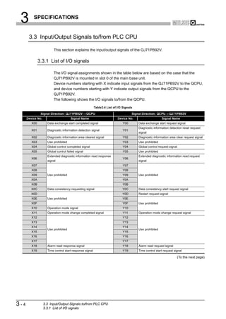
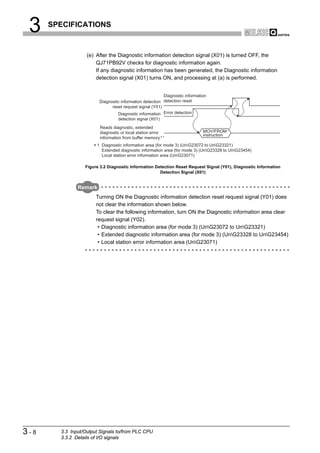
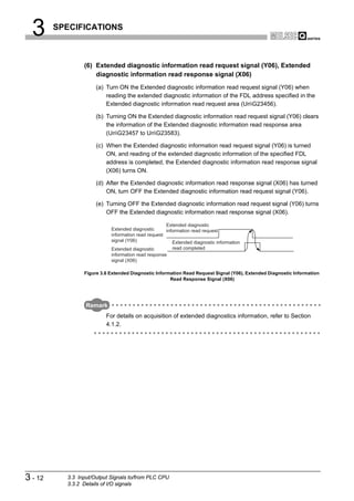
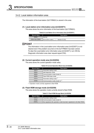
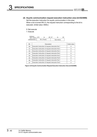
![3 SPECIFICATIONS
1
CHAPTER3 SPECIFICATIONS
OVERVIEW
This chapter explains the performance and transmission specifications of the QJ71PB92V.
For details of the general specifications, refer to the QCPU User's Manual (Hardware
Design, Maintenance and Inspection).
2
3.1 Performance Specifications
CONFIGURATION
SYSTEM
The performance specifications of the QJ71PB92V are given below.
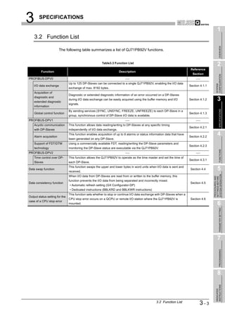
Table3.1 Performance Specifications
Item Specifications
3
PROFIBUS-DP station type DP-Master (Class 1)
SPECIFICATIONS
Transmission specifications
Electrical standard/
EIA-RS485 compliant
characteristics
Medium Shielded twisted pair cable ( Section 5.5.1)
Network topology Bus topology (Tree topology when repeaters are used)
• Between DP-Master and DP-Master: Token passing method 4
Data link method
• Between DP-Master and DP-Slave: Polling method
Encoding method NRZ
Transmission speed *1 9.6 kbps to 12 Mbps ( (1) in this section)
FUNCTIONS
Transmission distance Differs depending on the transmission speed( (1) in this section)
Max. No. of repeaters 3 repeaters
Max. No. of stations 32 per segment (including repeater(s))
Max. No. of DP-Slaves 125 per QJ71PB92V 5
I/O data Input data Max. 8192 bytes (Max. 244 bytes per DP-Slave)
SYSTEM OPERATION
PROCEDURES AND
SETTINGS BEFORE
size Output data Max. 8192 bytes (Max. 244 bytes per DP-Slave)
Number of writes to flash
Max. 100000 times
ROM
No. of occupied I/O points 32 (I/O assignment: 32 intelligent points)
Internal current consumption
0.57 A
(5VDC) 6
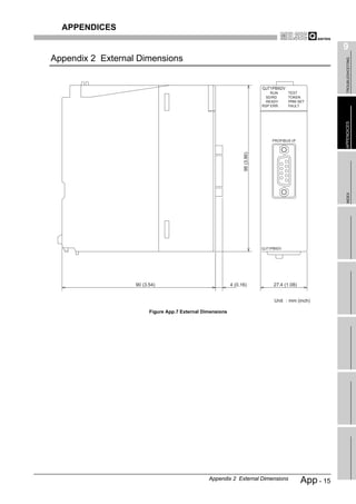
External dimensions 98(3.86 in.) (H) x 27.4(1.08 in.) (W) x 90(3.54 in.) (D) [mm]
PARAMETER SETTING
Weight 0.13 kg
* 1 The transmission speed is controlled within 0.2%. (Compliant with IEC 61158-2)
7
PROGRAMMING
8
INSTRUCTIONS
DEDICATED
3.1 Performance Specifications 3-1](https://image.slidesharecdn.com/qj71pb92v-091101233248-phpapp01/85/Qj71-Pb92-V-27-320.jpg)
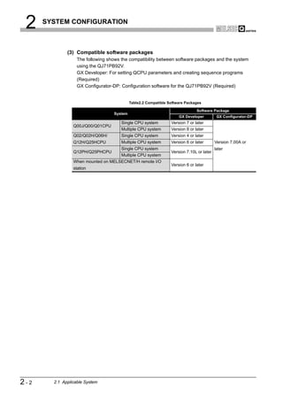
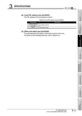
![3 SPECIFICATIONS
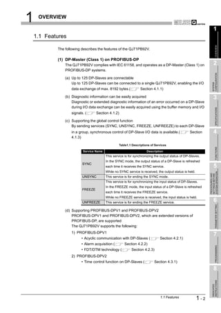
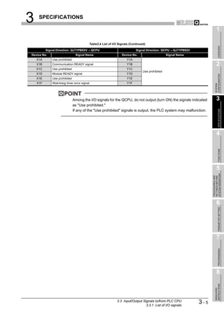
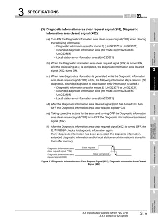
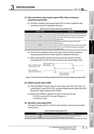
(1) Transmission distance
Table3.2 Transmission Distance
Max. Transmission Distance when
Transmission Speed Transmission Distance
Repeater is Used *1
9.6 kbps
19.2 kbps 1200 m (3937 ft.)/segment 4800 m (15748 ft.)/network
93.75 kbps
187.5 kbps 1000 m (3281 ft.)/segment 4000 m (13123 ft.)/network
500 kbps 400 m (1312 ft.)/segment 1600 m (5249 ft.)/network
1.5 Mbps 200 m (656 ft.)/segment 800 m (2625 ft.)/network
3 Mbps
6 Mbps 100 m (328 ft.)/segment 400 m (1312 ft.)/network
12 Mbps
* 1 The max. transmission distance in the table above is based on the case where 3 repeaters are
used.
The calculation formula for the transmission distance extended using a repeater(s) is:
Max. transmission distance [m/network] = (Number of repeaters + 1) x Transmission distance [m/segment]
3-2 3.1 Performance Specifications](https://image.slidesharecdn.com/qj71pb92v-091101233248-phpapp01/85/Qj71-Pb92-V-28-320.jpg)
![3 SPECIFICATIONS
1
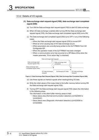
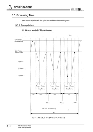
(a) Bus cycle time (Bc) calculation formula
The bus cycle time (Bc) of the DP-Master can be obtained from the following
OVERVIEW
calculation formula.
The symbols within the brackets [] indicate units.
n
Bc[s] Max (MSI,
i 1
(Pt (i) Tsdi (M)) Lr) 2
n=number of DP-Slaves
CONFIGURATION
Max (A, B) = A or B, whichever is greater
SYSTEM
Table3.20 Items in the bus cycle time (Bc) calculation formula
Item Description
MSI[s] Minimum polling cycle (Min. slave interval) *1 3
(Polling time to i-th station) = Treq(i) + Max_Tsdr(i)+ Tres(i)
SPECIFICATIONS
• Treq(i)[s] = (Request transmission time of i-th station)
= [{(Number of bytes output to i-th station) + 9} 11[bit]] / (Transmission speed[bps])
Pt(i)[s]
• Max_Tsdr(i)[s] = (Response time [TBit] of i-th station) *2, *3 / (Transmission speed[bps])
• Tres(i)[s] = (Response transmission time of i-th station)
= [{(Number of bytes input from i-th station) + 9} 11[bit]] / (Transmission speed[bps])
4
(Request/response processing time [TBit] of DP-Master(QJ71PB92V)*4 / (Transmission
Tsdi(M)[s]
speed[bps])
FUNCTIONS
Lr[s] (Data refresh time) = 5.50 10-3 + (Number of DP-Slaves) 100 10-6
* 1 The value set on the Master Settings screen of GX Configurator-DP
* 2 The MaxTsdr value described in the GSD (DDB) file of the DP-Slave
* 3 [TBit] (Bit Time) is a unit that expresses the time required for 1-bit data transmission as "1". 5
The actual processing time differs as shown below depending on the transmission speed.
SYSTEM OPERATION
PROCEDURES AND
SETTINGS BEFORE
[Transmission speed is 1.5 Mbps]
1[TBit]=1 / (1.5 106)=0.667 10 -6[s]
[Transmission speed is 12 Mbps]
1[TBit]=1 / (12 106)=0.083 10 -6[s]
* 4 The Tsdi value described in the GSD (DDB) file of the QJ71PB92V
The Tsdi value varies as shown below depending on the transmission speed.
Refer to *3 for the unit [TBit]. 6
PARAMETER SETTING
Table3.21 Request/Response Processing Time of DP-Master
Transmission Speed Request/Response Processing Time of DP-Master
9.6 kbps 10 TBit
19.2 kbps, 93.75 kbps 15 TBit
197.5 kbps, 500 kbps 80 TBit
1.5 Mbps, 3 Mbps, 6 Mbps, 12 Mbps, 150 TBit 7
PROGRAMMING
8
INSTRUCTIONS
DEDICATED
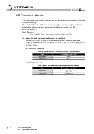
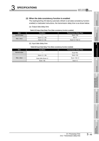
3.5 Processing Time
3.5.1 Bus cycle time
3 - 45](https://image.slidesharecdn.com/qj71pb92v-091101233248-phpapp01/85/Qj71-Pb92-V-71-320.jpg)
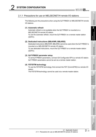
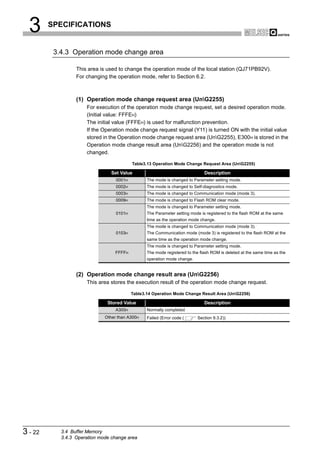
![3 SPECIFICATIONS
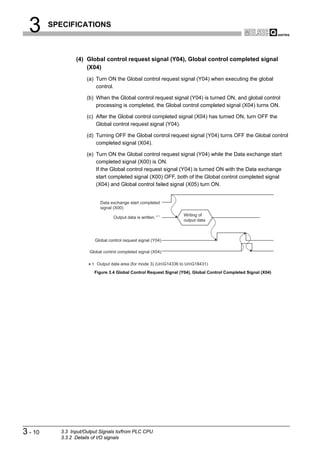
(b) Bus cycle time calculation example
The following shows a calculation example of the bus cycle time:
Transmission speed : 1.5Mbps
DP-Master (FDL address 0) : 3 modules
No. of DP-Slave
QJ71PB92V
PROFIBUS-DP
DP-Slave (FDL address 1) DP-Slave (FDL address 2) DP-Slave (FDL address 3)
AJ95TB2-16T AJ95TB3-16D QJ71PB93D
Input : 0 points Input : 16 points Input : 1 word
Output: 16 points Output: 0 points Output: 2 words
AJ95TB2-16T AJ95TB3-16D QJ71PB93D
Output data size [byte] 2 0 4
Input data size [byte] 0 2 2
Figure 3.29 System Configuration Example
1) MSI[s] value
MSI[s]=80 100 10-6=8.0 10-3
2) Pt(i)[s] value
Table3.22 Pt(i) Value
DP-Slave
Item
AJ95TB2-16T (FDL address 1) AJ95TB3-16D (FDL address 2) QJ71PB93D (FDL address 3)
{(2 + 9) 11} (1.5 106) {(0 + 9) 11} (1.5 106) {(4 + 9) 11} (1.5 106)
Treq(i)[s]
= 0.081 10-3 = 0.066 10-3 = 0.095 10-3
Response time
150 150 150
[TBit] of i-th station
Max_Tsdr(i)[s] 150 (1.5 106) = 0.1 10-3 150 (1.5 106) = 0.1 10-3 150 (1.5 106) = 0.1 10-3
{(0 + 9) 11} (1.5 106) {(2 + 9) 11} (1.5 106) {(2 + 9) 11} (1.5 106)
Tres(i)[s]
-3 -3 -3
= 0.066 10 = 0.081 10 = 0.081 10
-3 -3 -3 -3
0.081 10 + 0.1 10 + 0.066 0.066 10 + 0.1 10 + 0.081 0.095 10-3 + 0.1 10-3 + 0.081
Pt(i)[s] 10-3 10-3 10-3
-3 -3
= 0.247 10 = 0.247 10 = 0.276 10-3
3) Tsdi(M)[s] value
Request/response processing time [TBit] of DP-Master (QJ71PB92V)=150
Tsdi(M)[s]=150 / (1.5 106)=0.1 10-3
4) Lr[s] value
Lr[s]=5.50 10-3+3 100 10-6=5.80 10-3
Using the values obtained in above 2) to 4),
3
(Pt (i) Tsdi (M)) Lr {(Pt (1) Tsdi (M)) (Pt (2) Tsdi (M)) (Pt (3) Tsdi (M))} Lr
i 1
{ (0.347 10 3 ) (0.347 10 3 ) (0.376 10 3 )} 5.80 10 3
3 3
1.07 10 5.80 10
3
6.87 10
Therefore, the bus cycle time (Bc) value is as follows:
3
Bc[s] Max (MSI , (Pt (i) Tsdi (M)) Lr)
i 1
Max (8.0 10 3 , 6.87 10 3 )
8.0 10 3 [s]
3 - 46 3.5 Processing Time
3.5.1 Bus cycle time](https://image.slidesharecdn.com/qj71pb92v-091101233248-phpapp01/85/Qj71-Pb92-V-72-320.jpg)
![3 SPECIFICATIONS
1
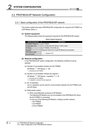
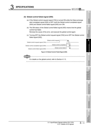
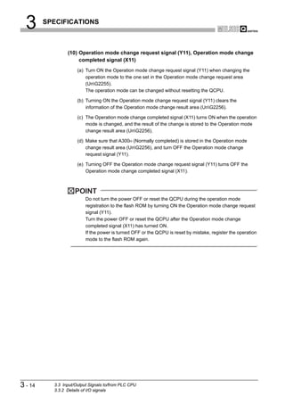
(2) When multiple DP-Masters are used
The bus cycle time (Bc) can be obtained by the following calculation formula when
OVERVIEW
there are multiple DP-Masters on the same network:
n
TBc[s] Bc (n)
i 1
n Number of DP-Masters
2
Bc Bus cycle time of each DP-Master ( (1) in this section)
CONFIGURATION
The following shows an example where two DP-Masters exist on the same network.
SYSTEM
DP-Master 1 executes polling DP-Master 2 executes polling DP-Master 1 executes polling
3
DP-Master 2 bus cycle Time
DP-Master 1 bus cycle
time Bc(1) time Bc(2)
SPECIFICATIONS
TBc
Figure 3.30 Bus Cycle Time When Two DP-Masters Exist on the Same Network 4
FUNCTIONS
5
SYSTEM OPERATION
PROCEDURES AND
SETTINGS BEFORE
6
PARAMETER SETTING
7
PROGRAMMING
8
INSTRUCTIONS
DEDICATED
3.5 Processing Time
3.5.1 Bus cycle time
3 - 47](https://image.slidesharecdn.com/qj71pb92v-091101233248-phpapp01/85/Qj71-Pb92-V-73-320.jpg)
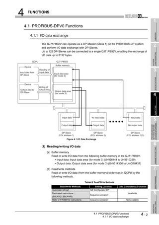
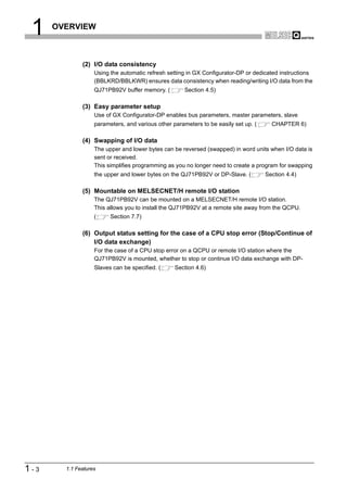
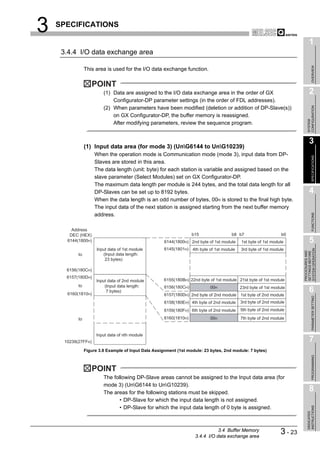
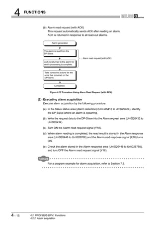
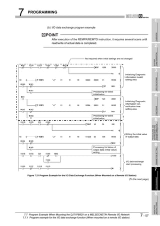
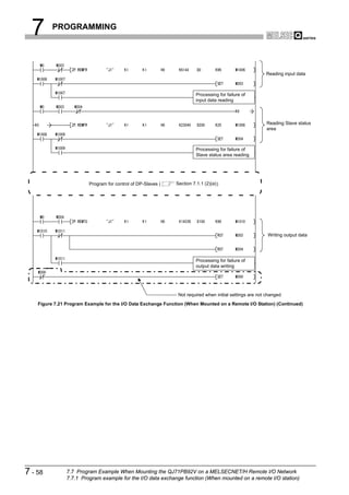
![4 FUNCTIONS
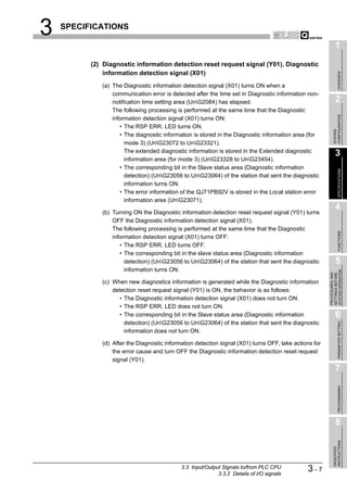
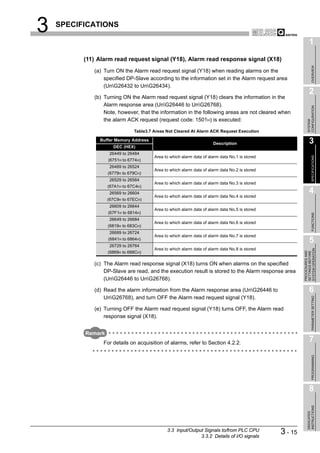
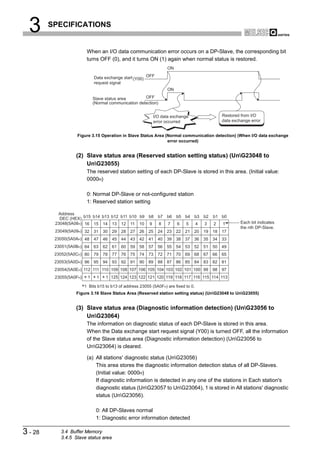
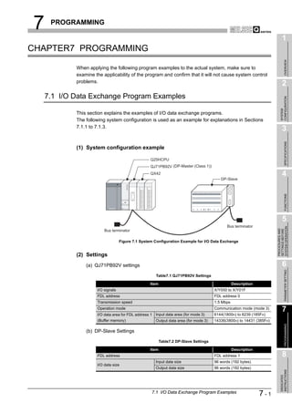
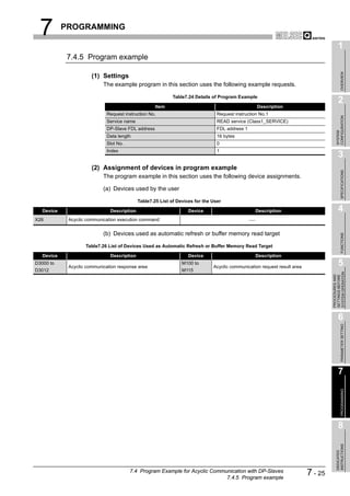
(2) Starting and stopping I/O data exchange
(a) Write the initial value of the output data to the Output data area (for mode 3)
(UnG14336 to UnG18431).
(b) Turn ON the Data exchange start request signal (Y00).
(c) When I/O data exchange is started after turning ON the Data exchange start
request signal (Y00), the Data exchange start completed signal (X00) turns ON.
(d) Input data from DP-Slaves are stored in the Input data area (for mode 3)
(UnG6144 to UnG10239).
(e) Turning OFF the Data exchange start request signal (Y00) stops I/O data
exchange.
[Input data exchange]
Data exchange start
request signal(Y00)
Data exchange start
completed signal(X00)
Bus cycle time (Bc) Bc Bc Bc
I/O data exchange I/O data exchange
started stopped
Input data area (for mode 3) Data of previous exchange Input data Input data Input data
(UnG6144 to UnG10239) at Bc at Bc at Bc
[Output data exchange]
Data exchange start
request signal(Y00)
Data exchange start
completed signal(X00)
Bus cycle time (Bc) Bc Bc Bc
I/O data exchange I/O data exchange
started stopped
Output data area (for mode 3) Output data Output data Output data Output data
(UnG14336 to UnG18431) at Bc at Bc at Bc at Bc
Figure 4.2 I/O Data Exchange Processing
Remark
For program examples for the I/O data exchange function, refer to Sections 7.1
and 7.7.
4-3 4.1 PROFIBUS-DPV0 Functions
4.1.1 I/O data exchange](https://image.slidesharecdn.com/qj71pb92v-091101233248-phpapp01/85/Qj71-Pb92-V-78-320.jpg)
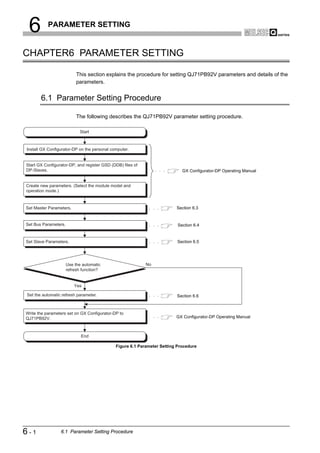
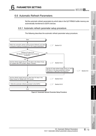
![6 PARAMETER SETTING
1
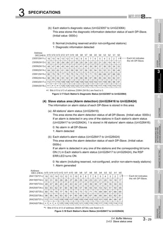
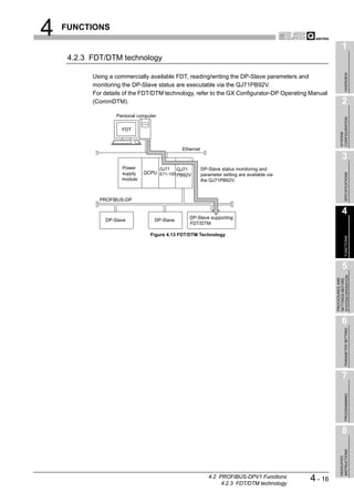
6.3 Master Parameters
OVERVIEW
Set the QJ71PB92V's transmission speed, FDL address and other parameters.
(1) Start procedure
2
(a) Right-click on the DP-Master graphic [Modify Settings].
CONFIGURATION
SYSTEM
3
Right-click on the graphic.
Figure 6.2 Master Settings Screen Start Procedure
SPECIFICATIONS
(2) Setting items
4
FUNCTIONS
5
SYSTEM OPERATION
PROCEDURES AND
SETTINGS BEFORE
6
PARAMETER SETTING
7
Figure 6.3 Master Settings Screen
PROGRAMMING
Table6.2 Master Parameter Setting Items
Item Description
Set the name of the DP-Master.
Name
Setting range: Up to 17 alphanumeric characters
Baudrate
Set the transmission speed of the PROFIBUS-DP. 8
Setting range: 9.6 kbps to 12 Mbps (Default: 1.5 Mbps)
Set the FDL address.
FDL address
INSTRUCTIONS
Setting range: 0 to 125 (Default: 0)
DEDICATED
(To the next page)
6.3 Master Parameters 6-4](https://image.slidesharecdn.com/qj71pb92v-091101233248-phpapp01/85/Qj71-Pb92-V-113-320.jpg)
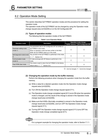
![6 PARAMETER SETTING
1
6.4 Bus Parameters
OVERVIEW
Set the PROFIBUS-DP parameters.
Normally, the bus parameters are used as default values.
When changing some of the bus parameters, make sure of the PROFIBUS-DP standard in
advance. 2
CONFIGURATION
(1) Start procedure
(a) Right-click on the graphic of DP-Master [Modify Settings].
SYSTEM
(b) Click the Bus Param. button in the Master Settings screen.
3
(2) Setting items
SPECIFICATIONS
4
FUNCTIONS
5
SYSTEM OPERATION
PROCEDURES AND
SETTINGS BEFORE
Figure 6.4 Bus Parameter Screen 6
PARAMETER SETTING
Table6.3 Bus Parameter Setting Items
Item Description
Sets the transmission speed of the PROFIBUS-DP.
When the set value is changed on this screen, the "Baudrate" value in the master parameter settings is
Select Baudrate
also changed automatically.
Setting range: 9.6 kbps to 12 Mbps (Default: 1.5 Mbps)
Set the slot time (maximum time for waiting for a response).
7
Slot Time (T_sl) If this set time is exceeded, an error will be detected.
Setting range: 37 to 16383 (Unit: TBit, Default: 300 TBit)
PROGRAMMING
Set the minimum response time of responders.
min T_sdr
Setting range: 11 to 1023 (Unit: TBit, Default: 11 TBit)
Set the maximum response time of responders.
max T_sdr
Setting range: 37 to 1023 (Unit: TBit, Default: 150 TBit)
Set the repeater switching time (the time required for switching the transmission direction of the 8
repeater).
Quiet Time (T_qui)
Set 0 when the network does not contain a repeater.
INSTRUCTIONS
Setting range: 0 to 127 (Unit: TBit, Default: 0 TBit)
DEDICATED
(To the next page)
6.4 Bus Parameters 6-6](https://image.slidesharecdn.com/qj71pb92v-091101233248-phpapp01/85/Qj71-Pb92-V-115-320.jpg)
![6 PARAMETER SETTING
Table6.3 Bus Parameter Setting Items (Continued)
Item Description
Set the setup time.
Setup Time (T_set)
Setting range: 1 to 255 (Unit: TBit, Default: 1 TBit)
Set the target token rotation time.
Target Rot. Time (T_tr)
Setting range: 256 to 16777215 (Unit: TBit, Default: 50000 TBit)
Set a constant for controlling the GAP update time (T_gud).
GAP factor
Setting range: 1 to 100 (Default: Depends on the transmission speed)
Set the highest FDL address of DP-Slaves that exist on the network.
HSA
Setting range: 2 to 126 (Default: 126)
Set the maximum number of retries for individual data transmission.
Max retry limit
Setting range: 1 to 7 (Default: Depends on the transmission speed)
Remark
[TBit] (Bit Time) is a unit that expresses the time required for 1-bit data
transmission as "1".
The actual processing time differs as shown below depending on the transmission
speed.
• In the case of 1.5 Mbps, 1[TBit]=1 / (1.5 106)=0.667 10-6[s]
• In the case of 12 Mbps, 1[TBit]=1 / (12 106)=0.083 10-6[s]
TBit is converted into ms automatically on GX Configurator-DP.
The results of the conversion (ms) are displayed on the right side of the screen.
(3) Precautions for bus parameter setting
For each set value of the max T_sdr, Quiet Time (T_qui) and Setup Time (T_set), set
the maximum value among those of the stations connected to PROFIBUS-DP
(including the DP-Master).
The default value of the QJ71PB92V varies depending on the transmission speed.
Table6.4 Default Values of max T_sdr, Quiet Time (T_qui) and Setup Time (T_set)
Default Values of QJ71PB92V
Item 187.5kbps
500kbps 1.5Mbps 3Mbps 6Mbps 12Mbps
or less
max T_sdr 60 100 150 250 450 800
Quiet Time (T_qui) 0 0 0 3 6 9
Setup Time (T_set) 1 1 1 4 8 16
6-7 6.4 Bus Parameters](https://image.slidesharecdn.com/qj71pb92v-091101233248-phpapp01/85/Qj71-Pb92-V-116-320.jpg)
![6 PARAMETER SETTING
1
6.5 Slave Parameters
OVERVIEW
Set parameters for each DP-Slave.
(1) Start procedure
2
(a) Right-click on the graphic of DP-Master [Insert DP-Slave].
CONFIGURATION
(b) Select a DP-Slave in the Device Database screen.
SYSTEM
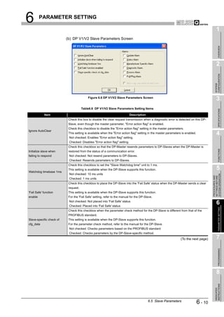
(2) Setting items
(a) Slave Parameter Settings screen
3
SPECIFICATIONS
4
FUNCTIONS
5
SYSTEM OPERATION
PROCEDURES AND
SETTINGS BEFORE
6
PARAMETER SETTING
Figure 6.5 Slave Parameter Settings Screen
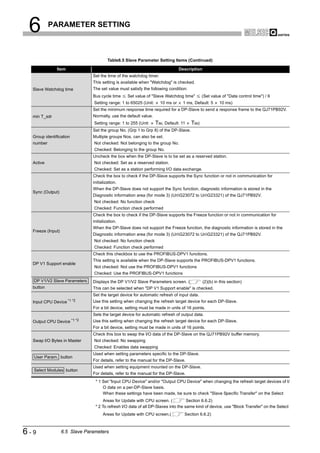
Table6.5 Slave Parameter Setting Items
Item Description
Set the name of the DP-Slave.
Name
Setting range: max. 17 alphanumeric characters
Set the FDL address.
7
FDL Address
Setting range: 0 to 125
Check this checkbox to use a watchdog timer.
PROGRAMMING
When this setting is enabled, a communication error is detected if no data are received from the
QJ71PB92V within the time specified in "Slave Watchdog time".
(When disabled, a communication error is not detected even if data are no longer received from the
Watchdog QJ71PB92V.)
Once the "Watchdog" checkbox has been checked in the master parameter setting, "Watchdog" in the 8
slave parameters cannot be set.
Not checked: Watchdog timer disabled (Default)
INSTRUCTIONS
Checked: Watchdog timer enabled
DEDICATED
(To the next page)
6.5 Slave Parameters 6-8](https://image.slidesharecdn.com/qj71pb92v-091101233248-phpapp01/85/Qj71-Pb92-V-117-320.jpg)
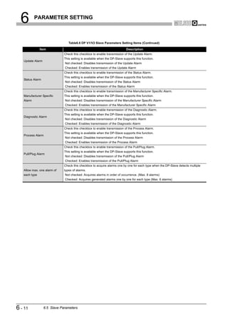
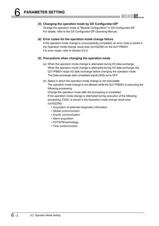
![6 PARAMETER SETTING
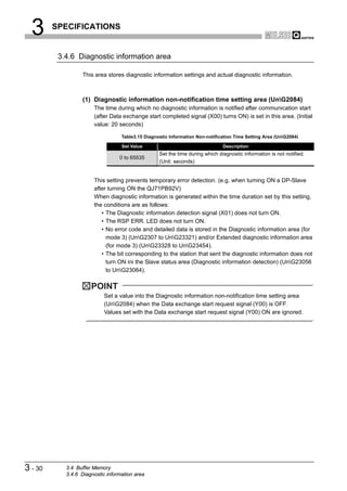
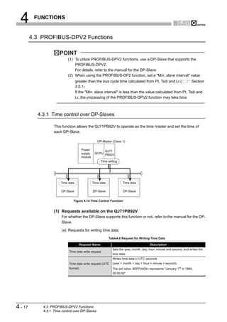
6.6.2 Automatic Refresh Settings (Select Areas for Update with CPU)
(1) Start procedure
(a) [Setup] [AutoRefresh Settings]
(2) Setting items
Figure 6.8 Writing Automatic Refresh Parameters
Table6.7 Setting Items for Automatic Refresh Settings (Select Areas for Update with CPU)
Item Description
Check this checkbox to enable the "Addresses in MELSEC CPU Memory" setting in the slave
parameters.
Check the box to change the refresh target device on a per-DP-Slave basis.
Slave Specific Transfer
When "Slave Specific Transfer" is checked, "Block Transfer" is unchecked.
Not checked: Disables the "Addresses in MELSEC CPU Memory" setting in slave parameters.
Checked: Enables the "Addresses in MELSEC CPU Memory" setting in slave parameters.
Check this checkbox to refresh I/O data of all DP-Slaves into the same kind of device.
When "Block Transfer" is checked, "Slave Specific Transfer" is unchecked.
Block Transfer
Not checked: Not refresh I/O data of all DP-Slaves into the same kind of device
Checked: Refresh I/O data of all DP-Slaves into the same kind of device.
Set the target device for automatic refresh of input data.
Input
For a bit device, setting must be made in units of 16 points.
Set the target device for automatic refresh of output data.
Output
For a bit device, setting must be made in units of 16 points.
Set the target device for automatic refresh of the Diagnostic information area (for mode 3) (UnG23072 to
Comm. Trouble Area
UnG23321).
Set the target device for automatic refresh of the Extended diagnostic information area (for mode 3)
Extd. Comm. Trouble Area
(UnG23328 to UnG23454).
Set the automatic refresh target devices of the following areas.
• Slave status area (Normal communication detection) (UnG23040 to UnG23047)
Slave Status Area
• Slave status area (Reserved station setting status) (UnG23048 to UnG23055)
• Slave status area (Diagnostic information detection) (UnG23056 to UnG23064)
6 - 13 6.6 Automatic Refresh Parameters
6.6.2 Automatic Refresh Settings (Select Areas for Update with CPU)](https://image.slidesharecdn.com/qj71pb92v-091101233248-phpapp01/85/Qj71-Pb92-V-122-320.jpg)
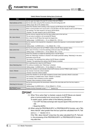
![6 PARAMETER SETTING
6.6.3 Writing Automatic Refresh Parameters
Write the automatic refresh parameters to the QCPU.
Reset the QCPU after writing the automatic refresh parameters.
(1) Start procedure
(a) [Actions] [Access Master Module]
(2) Setting items
Check "Update Autorefresh" and click the Download button.
Figure 6.9 Writing Automatic Refresh Parameters
POINT
When automatic refresh parameters were written from GX Configurator-DP while
GX Developer was running, they are not displayed in file lists such as Read from
PLC, Delete PLC data on GX Developer.
Update the file lists by the Refresh view button of the Read from PLC or Delete
PLC data on GX Developer.
6 - 15 6.6 Automatic Refresh Parameters
6.6.3 Writing Automatic Refresh Parameters](https://image.slidesharecdn.com/qj71pb92v-091101233248-phpapp01/85/Qj71-Pb92-V-124-320.jpg)


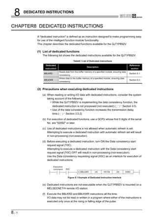
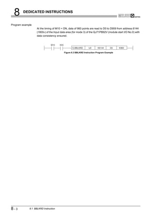
![8 DEDICATED INSTRUCTIONS
1
8.1 BBLKRD Instruction
OVERVIEW
Table8.2 Device Usable in the BBLKRD Instruction
Usable device
Internal device MELSECNET/10(H) Special
Index
Set data (System, user) File Direct J function
register
Constant
Other
2
register module K, H
Bit Word Bit Word Z
U G
CONFIGURATION
n1
SYSTEM
D
n2
3
SPECIFICATIONS
[Instruction [Execution
symbol] condition]
Command
BBLKRD G.BBLKRD Un n1 D n2
Figure 8.2 BBLKRD Instruction
4
Set data
Table8.3 Set Data in the BBLKRD Instruction
FUNCTIONS
Set data Description Setting range Data type
Un QJ71PB92V module start I/O number 0 to FFH
BIN 16 bits
n1 Start address of reading data Specified device range
D Start No. of the device to which read data are stored Specified device range Device name 5
SYSTEM OPERATION
n2 Number of read data 1 to 4096 (word) BIN 16 bits
PROCEDURES AND
SETTINGS BEFORE
Function
This instruction allows data reading from the buffer memory of a specified module with
data consistency ensured.
6
PARAMETER SETTING
Error
An operation error occurs in the following instances. (Error code: 4101)
• When a value outside the setting range is set to the set data field
• When the size, which is obtained by adding the number of read data to the start
address of reading data, exceeds the buffer memory size
• When the points available for the start address of reading data or after is less
than the number of read data
7
PROGRAMMING
8
INSTRUCTIONS
DEDICATED
8.1 BBLKRD Instruction 8-2](https://image.slidesharecdn.com/qj71pb92v-091101233248-phpapp01/85/Qj71-Pb92-V-187-320.jpg)
![8 DEDICATED INSTRUCTIONS
1
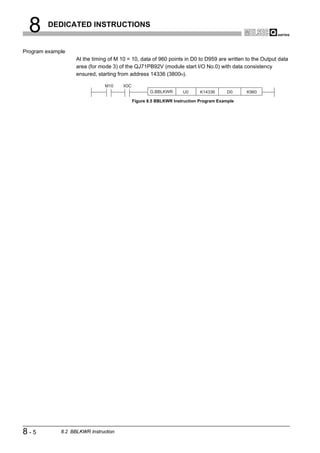
8.2 BBLKWR Instruction
OVERVIEW
Table8.4 Device Usable in the BBLKWR Instruction
Usable device
Internal device MELSECNET/10(H) Special
Index
Set data (System, user) File Direct J function
register
Constant
Other
2
register module K, H
Bit Word Bit Word Z
U G
CONFIGURATION
n1
SYSTEM
S
n2
3
SPECIFICATIONS
[Instruction [Execution
symbol] condition]
Command
BBLKWR G.BBLKWR Un n1 S n2
Figure 8.4 BBLKWR Instruction
4
Set data
Table8.5 Set Data in the BBLKWR Instruction
FUNCTIONS
Set data Description Setting range Data type
Un QJ71PB92V module start I/O number 0 to FFH
BIN 16 bits
n1 Start address for writing data Specified device range
S Start No. of the device storing write data Specified device range Device name 5
SYSTEM OPERATION
n2 Number of write data 1 to 4096 (word) BIN 16 bits
PROCEDURES AND
SETTINGS BEFORE
Function
This instruction allows data writing to the buffer memory of a specified module with data
consistency ensured.
6
Error
PARAMETER SETTING
An operation error occurs in the following instances. (Error code: 4101)
• When a value outside the setting range is set to the set data field
• When the size, which is obtained by adding the number of write data to the start
address for writing data, exceeds the buffer memory size
• When the points available for the start address for writing data or after is less than
the number of write data 7
PROGRAMMING
8
INSTRUCTIONS
DEDICATED
8.2 BBLKWR Instruction 8-4](https://image.slidesharecdn.com/qj71pb92v-091101233248-phpapp01/85/Qj71-Pb92-V-189-320.jpg)
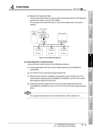
![9 TROUBLESHOOTING
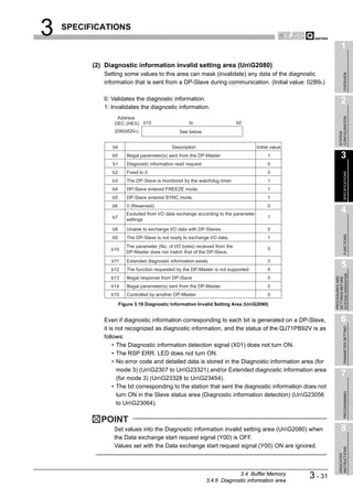
(2) Checking the LED status on GX Developer
The status of the QJ71PB92V's LEDs can be also checked on the H/W LED
Information screen (H/W LED information) of GX Developer.
For checking the LED status, use GX Developer Version 8.27D or later.
Start Procedure
[Diagnostics] [System monitor] Module's Detailed Information button
H/W Information button
Figure 9.1 H/W Information Screen
Table9.2 Values Displayed at H/W LED Information
Value Description
0000 The LED on the QJ71PB92V is OFF.
0001 The LED on the QJ71PB92V is ON.
Displaying "0000" and
The LED on the QJ71PB92V is flashing.
"0001" alternately.
9-2 9.1 Error Check Using the LEDs and Corrective Actions](https://image.slidesharecdn.com/qj71pb92v-091101233248-phpapp01/85/Qj71-Pb92-V-192-320.jpg)
![INDEX
[A] Diagnostic information detection signal (X01)•••••• 3-7
ABORT service (Class2_SERVICE) •••••••••••••••• 7-23 Diagnostic information invalid setting area ••••••••3-31
Acquisition of diagnostic and/or extended diagnostic Diagnostic information non-notification time setting
information •••••••••••••••••••••••••••••••••••••••••••••••• 4-4 area •••••••••••••••••••••••••••••••••••••••••••••••••••••••3-30
Acyclic communication area•••••••••••••••••••••••••• 3-39
Acyclic communication request area ••••••••••••••• 3-39 [E]
Acyclic communication request execution instruction Each station's alarm status •••••••••••••••••••••••••••3-29
area ••••••••••••••••••••••••••••••••••••••••••••••••••••••• 3-40 Each station's diagnostic status •••••••••••••••••••••3-29
Acyclic communication request result area•••••••• 3-41 Error check using the LEDs and corrective actions9-1
Acyclic communication response area ••••••••••••• 3-42 Error Codes ••••••••••••••••••••••••••••••••••••••••••••••• 9-5
Acyclic communication with DP-Slaves •••••••••••• 4-11 Extended diagnostic information area (for mode 3)
Address information area (for mode 3) ••••••••••••• 3-25 •••••••••••••••••••••••••••••••••••••••••••••••••••••••••••••3-34
Alarm ACK request••••••••••••••••••••••••••••••••••••• 7-32 Extended diagnostic information read area••••••••3-35
Alarm acquisition ••••••••••••••••••••••••••••••••••••••• 4-14 Extended diagnostic information read request area
Alarm area ••••••••••••••••••••••••••••••••••••••••••••••• 3-43 •••••••••••••••••••••••••••••••••••••••••••••••••••••••••••••3-35
Alarm read request signal (Y18) ••••••••••••••••••••• 3-15 Extended diagnostic information read request signal
Alarm read request (with ACK) •••••••••••••••••••••• 7-37 (Y06) ••••••••••••••••••••••••••••••••••••••••••••••••••••••3-12
Alarm read request (without ACK) •••••••••••••••••• 7-28 Extended diagnostic information read response area
Alarm read response signal (X18)••••••••••••••••••• 3-15 •••••••••••••••••••••••••••••••••••••••••••••••••••••••••••••3-35
Alarm request area ••••••••••••••••••••••••••••••••••••• 3-43 Extended diagnostic information read response signal
Alarm response area••••••••••••••••••••••••••••••••••• 3-43 (X06) ••••••••••••••••••••••••••••••••••••••••••••••••••••••3-12
All stations' alarm status •••••••••••••••••••••••••••••• 3-29
All stations' diagnostic status••••••••••••••••••••••••• 3-28 [F]
Automatic Refresh Parameters •••••••••••••••••••••• 6-12
FDT/DTM technology ••••••••••••••••••••••••••••••••••4-16
Flash ROM storage mode ••••••••••••••••••••••••••••3-20
[B]
Functions •••••••••••••••••••••••••••••••••••••••••••••••••• 4-1
BBLKRD Instruction••••••••••••••••••••••••••••••••••••• 8-2
BBLKWR Instruction •••••••••••••••••••••••••••••••••••• 8-4 [G]
Buffer memory list •••••••••••••••••••••••••••••••••••••• 3-17
Bus cycle time••••••••••••••••••••••••••••••••••••••••••• 3-44 Global control area •••••••••••••••••••••••••••••••••••••3-37
Bus cycle time area •••••••••••••••••••••••••••••••••••• 3-36 Global control completed signal (X04)••••••••••••••3-10
Bus parameters •••••••••••••••••••••••••••••••••••••••••• 6-6 Global control failed signal (X05) ••••••••••••••••••••3-11
Global control function •••••••••••••••••••••••••••••••••• 4-7
Global control request signal (Y04) •••••••••••••••••3-10
[C]
Checking the LED status on GX Developer •••••••• 9-2 [H]
Communication READY signal (X1B) •••••••••••••• 3-16
Connector ••••••••••••••••••••••••••••••••••••••••••••••••• 5-7 How to return the QJ71PB92V to Its factory-set
Current bus cycle time••••••••••••••••••••••••••••••••• 3-36 conditions ••••••••••••••••••••••••••••••••••••••••••••••••9-18
Current operation mode area •••••••••••••••••••••••• 3-20
[I]
[D] INITIATE service (Class2_SERVICE) ••••••••••••••7-19
Data consistency function••••••••••••••••••••••••••••• 4-21 Input data area (for mode 3)••••••••••••••••••••••••••3-23
Data consistency requesting signal (X0C) ••••••••• 3-13 Input data start address area (for mode 3) ••••••••3-26
Data consistency start request signal (Y0C) •••••• 3-13 I/O data exchange ••••••••••••••••••••••••••••••••••••••• 4-2
Data exchange start completed signal (X00)••••••• 3-6 I/O data exchange area •••••••••••••••••••••••••••••••3-23
Data exchange start request signal (Y00) •••••••••• 3-6
Data swap function ••••••••••••••••••••••••••••••••••••• 4-19 [L]
Diagnostic information area •••••••••••••••••••••••••• 3-30 List of I/O signals •••••••••••••••••••••••••••••••••••••••• 3-4
Diagnostic information area clear request signal (Y02) Local FDL address area•••••••••••••••••••••••••••••••3-21
•••••••••••••••••••••••••••••••••••••••••••••••••••••••••••••• 3-9 Local station error information area •••••••••••••••••3-20
Diagnostic information area cleared signal (X02) • 3-9 Local station information area••••••••••••••••••••••••3-20
Diagnostic information area (for mode 3) •••••••••• 3-32
Diagnostic information detection reset request signal [M]
(Y01) ••••••••••••••••••••••••••••••••••••••••••••••••••••••• 3-7
Master parameters •••••••••••••••••••••••••••••••••••••• 6-4
Index - 1](https://image.slidesharecdn.com/qj71pb92v-091101233248-phpapp01/85/Qj71-Pb92-V-224-320.jpg)
![Max. bus cycle time •••••••••••••••••••••••••••••••••••• 3-36 [W]
Min. bus cycle time ••••••••••••••••••••••••••••••••••••• 3-36 Watchdog timer error signal (X1F) ••••••••••••••••••3-16
9
Module READY signal (X1D)••••••••••••••••••••••••• 3-16 Wiring specifications for bus terminator ••••••••••••• 5-7
TROUBLESHOOTING
WRITE services (Class1_SERVICE,
[O] Class2_SERVICE) •••••••••••••••••••••••••••••••••••••7-16
Offline test status area •••••••••••••••••••••••••••••••• 3-21
Operation mode change area •••••••••••••••••••••••• 3-22
Operation mode change completed signal (X11) 3-14
Operation mode change request area•••••••••••••• 3-22
Operation mode change request signal (Y11) •••• 3-14
Operation mode change result area •••••••••••••••• 3-22
Operation mode setting •••••••••••••••••••••••••••••••• 6-2
APPENDICES
Operation mode signal (X10)••••••••••••••••••••••••• 3-13
Output data area (for mode 3) ••••••••••••••••••••••• 3-24
Output data start address area (for mode 3) •••••• 3-26
Output status setting for the case of a CPU stop error
••••••••••••••••••••••••••••••••••••••••••••••••••••••••••••• 4-24
[P]
Parameter setting•••••••••••••••••••••••••••••••••••••••• 6-1
Performance specifications •••••••••••••••••••••••••••• 3-1
INDEX
Pin assignments of the PROFIBUS interface
connector•••••••••••••••••••••••••••••••••••••••••••••••••• 5-6
PROFIBUS cable •••••••••••••••••••••••••••••••••••••••• 5-6
PROFIBUS-DP network configuration••••••••••••••• 2-4
PROFIBUS-DPV0 Functions •••••••••••••••••••••••••• 4-2
PROFIBUS-DPV1 Functions ••••••••••••••••••••••••• 4-11
PROFIBUS-DPV2 Functions ••••••••••••••••••••••••• 4-17
[R]
READ services (Class1_SERVICE,
Class2_SERVICE) ••••••••••••••••••••••••••••••••••••• 7-13
Restart request signal (Y0D) ••••••••••••••••••••••••• 3-13
[S]
Self-diagnostics •••••••••••••••••••••••••••••••••••••••••• 5-5
Slave parameters•••••••••••••••••••••••••••••••••••••••• 6-8
Slave status area ••••••••••••••••••••••••••••••••••••••• 3-27
Slave status area (Alarm detection) •••••••••••••••• 3-29
Slave status area (Diagnostic information detection)
••••••••••••••••••••••••••••••••••••••••••••••••••••••••••••• 3-28
Slave status area (Normal communication detection)
••••••••••••••••••••••••••••••••••••••••••••••••••••••••••••• 3-27
Slave status area (Reserved station setting status)
••••••••••••••••••••••••••••••••••••••••••••••••••••••••••••• 3-28
[T]
Time control area ••••••••••••••••••••••••••••••••••••••• 3-43
Time control over DP-Slaves••••••••••••••••••••••••• 4-17
Time control setting request area ••••••••••••••••••• 3-43
Time control setting response area ••••••••••••••••• 3-43
Time control start request signal (Y19)••••••••••••• 3-16
Time control start response signal (X19) •••••••••• 3-16
Time data read request•••••••••••••••••••••••••••••••• 7-45
Time data write request ••••••••••••••••••••••••••••••• 7-49
Time data write request (UTC format) •••••••••••••• 7-47
Transmission delay time •••••••••••••••••••••••••••••• 3-48
Index - 2](https://image.slidesharecdn.com/qj71pb92v-091101233248-phpapp01/85/Qj71-Pb92-V-225-320.jpg)
![WARRANTY
Please confirm the following product warranty details before using this product.
1. Gratis Warranty Term and Gratis Warranty Range
If a.ny faults or defects (hereinafter "Failure") found to be the responsibility of Mitsubishi occurs during use of the product within
the gratis warranty term, the product shall be repaired at no cost via the sales representative or Mitsubishi Service Company.
However, if repairs are required onsite at domestic or overseas location, expenses to send an engineer will be solely at the
customer's discretion. Mitsubishi shall not be held responsible for any re-commissioning, maintenance, or testing on-site that
involves replacement of the failed module.
[Gratis Warranty Term]
The gratis warranty term of the product shall be for one year after the date of purchase or delivery to a designated place.
Note that after manufacture and shipment from Mitsubishi, the maximum distribution period shall be six (6) months, and the
longest gratis warranty term after manufacturing shall be eighteen (18) months. The gratis warranty term of repair parts shall
not exceed the gratis warranty term before repairs.
[Gratis Warranty Range]
(1) The range shall be limited to normal use within the usage state, usage methods and usage environment, etc., which follow
the conditions and precautions, etc., given in the instruction manual, user's manual and caution labels on the product.
(2) Even within the gratis warranty term, repairs shall be charged for in the following cases.
1. Failure occurring from inappropriate storage or handling, carelessness or negligence by the user. Failure caused by the
user's hardware or software design.
2. Failure caused by unapproved modifications, etc., to the product by the user.
3. When the Mitsubishi product is assembled into a user's device, Failure that could have been avoided if functions or
structures, judged as necessary in the legal safety measures the user's device is subject to or as necessary by industry
standards, had been provided.
4. Failure that could have been avoided if consumable parts (battery, backlight, fuse, etc.) designated in the instruction
manual had been correctly serviced or replaced.
5. Failure caused by external irresistible forces such as fires or abnormal voltages, and Failure caused by force majeure
such as earthquakes, lightning, wind and water damage.
6. Failure caused by reasons unpredictable by scientific technology standards at time of shipment from Mitsubishi.
7. Any other failure found not to be the responsibility of Mitsubishi or that admitted not to be so by the user.
2. Onerous repair term after discontinuation of production
(1) Mitsubishi shall accept onerous product repairs for seven (7) years after production of the product is discontinued.
Discontinuation of production shall be notified with Mitsubishi Technical Bulletins, etc.
(2) Product supply (including repair parts) is not available after production is discontinued.
3. Overseas service
Overseas, repairs shall be accepted by Mitsubishi's local overseas FA Center. Note that the repair conditions at each FA
Center may differ.
4. Exclusion of loss in opportunity and secondary loss from warranty liability
Regardless of the gratis warranty term, Mitsubishi shall not be liable for compensation of damages caused by any cause found
not to be the responsibility of Mitsubishi, loss in opportunity, lost profits incurred to the user by Failures of Mitsubishi products,
special damages and secondary damages whether foreseeable or not , compensation for accidents, and compensation for
damages to products other than Mitsubishi products, replacement by the user, maintenance of on-site equipment, start-up test
run and other tasks.
5. Changes in product specifications
The specifications given in the catalogs, manuals or technical documents are subject to change without prior notice.
6. Product application
(1) In using the Mitsubishi MELSEC programmable logic controller, the usage conditions shall be that the application will not
lead to a major accident even if any problem or fault should occur in the programmable logic controller device, and that
backup and fail-safe functions are systematically provided outside of the device for any problem or fault.
(2) The Mitsubishi programmable logic controller has been designed and manufactured for applications in general industries,
etc. Thus, applications in which the public could be affected such as in nuclear power plants and other power plants
operated by respective power companies, and applications in which a special quality assurance system is required, such
as for Railway companies or Public service purposes shall be excluded from the programmable logic controller
applications.
In addition, applications in which human life or property that could be greatly affected, such as in aircraft, medical
applications, incineration and fuel devices, manned transportation, equipment for recreation and amusement, and safety
devices, shall also be excluded from the programmable logic controller range of applications.
However, in certain cases, some applications may be possible, providing the user consults their local Mitsubishi
representative outlining the special requirements of the project, and providing that all parties concerned agree to the
special circumstances, solely at the users discretion.](https://image.slidesharecdn.com/qj71pb92v-091101233248-phpapp01/85/Qj71-Pb92-V-226-320.jpg)