Downloaded 16 times


![1Before starting use
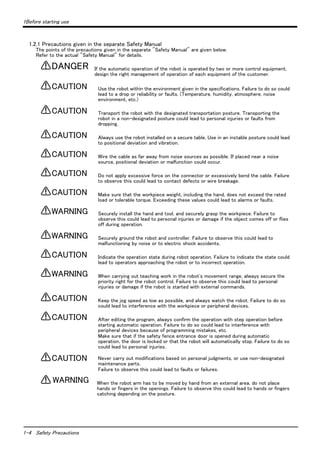
1.1.2 Symbols used in instruction manual
The symbols and expressions shown in Table 1-1 are used throughout this instruction manual. Learn the meaning
of these symbols before reading this instruction manual.
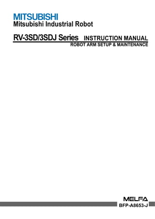
Table 1-1 : Symbols in instruction manual
Terminology Item/Symbol Meaning
Item
The "Robot controller" or the "Controller"
DANGER
WARNING
CAUTION
1-2 Using the instruction manuals
Indicates the controller which controls the robot arm.
Indicates the box which arranged control parts, such as robot CPU, servo
amplifier, and the safety circuit.
Symbol Precaution indicating cases where there is a risk of operator fatality or
serious injury if handling is mistaken. Always observe these precautions to
safely use the robot.
Precaution indicating cases where the operator could be subject to fatalities
or serious injuries if handling is mistaken. Always observe these precautions to
safely use the robot.
Precaution indicating cases where operator could be subject to injury or
physical damage could occur if handling is mistaken. Always observe these
precautions to safely use the robot.
[JOG]
If a word is enclosed in brackets or a box in the text, this refers to a key on
the teaching pendant.
[RESET] + [EXE]
(A) (B)
This indicates to press the (B) key while holding down the (A) key.
In this example, the [RESET] key is pressed while holding down the [+EXE]
key.
T/B This indicates the teaching pendant.
O/P This indicates the operating panel on the front of the controller.](https://image.slidesharecdn.com/bfp-a8653j-141003204745-conversion-gate01/85/Mitsubshi-10-320.jpg)


![2Unpacking to Installation
Setting the origin 2-19
2.4 Setting the origin
The origin is set so that the robot can be used with a high accuracy. After purchasing the robot, always carry out
this step before starting work. This step must also be carried out if the combination of robot and controller being
used is changed.
There are several methods for setting the origin, but the origin data input method will be explained here. Refer to
"5.6 Resetting the origin" on page 76 for the other methods.
The teaching pendant is required for this operation.
[Caution] If the origin data at shipment is erased due to out of battery, it is necessary to set the origin again.
Refer to "5.6 Resetting the origin" on page 76 and reset the origin using the jig method or ABS
method.
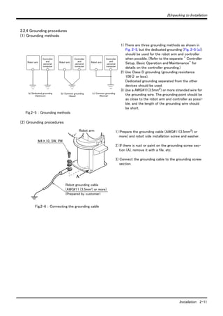
2.4.1 Installing the teaching pendant (T/B)
When installing and removing the T/B, turn off the controller power supply. If T/B is installed or removed in the
state of power supply ON, emergency stop alarm will occur.
If you use the robot wherein T/B is removed, please install the attached dummy connector. With the connector,
put the dummy connector or draw it out.
Please do not pull the cable of T/B strongly or do not bend it too much.
It becomes the breaking of a wire of the cable and the cause of breakage of the
connector. Please installing and removing so that stress does not start the cable
with the connector itself.
CAUTION
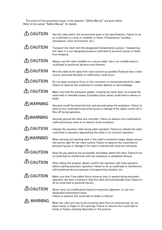
Explain the installation method of T/B below.
1) Check that the POWER (power supply) switch of the robot controller is OFF.
2) Connects T/B connector to the robot controller. Use as the upper surface the lock lever shown in Fig. 2-
13, and push in until there is sound.
Fig.2-13 : Installing and removing the T/B
The installation of T/B is finished.
(T/B)
Details of the A section
Lock lever
B
When removing the connector for T/B connection,
use lock release (state which raised the lock lever
to the up side), make the case of the B section
slide to the front, and remove and pull up out the latch.
T/B connector
Teaching pendant
Dummy connector
A部
◇◆◇ If error C0150 occurs ◇◆◇
At the time of the first power supply injection, error:C0150 (the serial number of the robot arm has not been
set up) occur the robot after purchase.
Parameter: Please input the serial number of the robot body into RBSERIAL. Refer to "instructions manual /
controller setup, and basic operation & maintenance" for the operation method.](https://image.slidesharecdn.com/bfp-a8653j-141003204745-conversion-gate01/85/Mitsubshi-27-320.jpg)
![2Unpacking to Installation
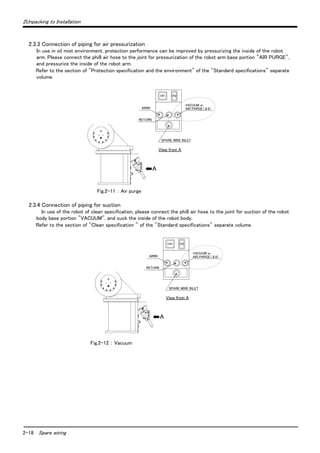
2.4.2 Setting the origin with the origin data input method
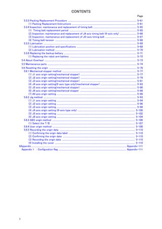
(1) Confirming the origin data
● Origin data history table (Origin Data History) Serial No.ES804008
Date Default . . . . . . . . .
D V!#S29
J 1 06DTYY
J 2 2?HL9X
J 3 1CP55V
J 4 T6!M$Y
J 5 Z2IJ%Z
J 6 A12%Z0
Method E E ・N ・S P E ・N ・
WARNING
CAUTION
2-20 Setting the origin
The origin data to be input is noted in the
origin data sheet enclosed with the arm,
or on the origin data history table
attached to the back side of the shoulder
cover A. (Refer to Fig. 2-14).
Referring to "5.3.2 Installing/removing
the cover" on page 58, remove the
shoulder cover A and confirm the value.
The value given in the default setting
column is the origin settings set with the
calibration jig before shipment.
Note that the 5-axis type does not have
the J4 axis.
S P
E ・N ・S P
(O: O(Alphabet), 0: Zero)
Note) Meanings of symbols in method column
E: Jig method
N: Not used
SP: Not used
Fig.2-14 : Origin data label (an example)
* The origin data to input is found on also the robot examination report sheet.
Always install/remove the cover with the controller control power turned OFF.
Failure to do so could lead to physical damage or personal injury should the robot
start moving due to incorrect operations.
(2) Turning ON the control power
Confirm that there are no operators near the robot before turning the power ON.
1) Turn the controller [POWER] switch ON.
The control power will be turned ON, and "o. 100" will appear on the STATUS NUMBER display on the
front of the controller.](https://image.slidesharecdn.com/bfp-a8653j-141003204745-conversion-gate01/85/Mitsubshi-28-320.jpg)
![2Unpacking to Installation
Setting the origin 2-21
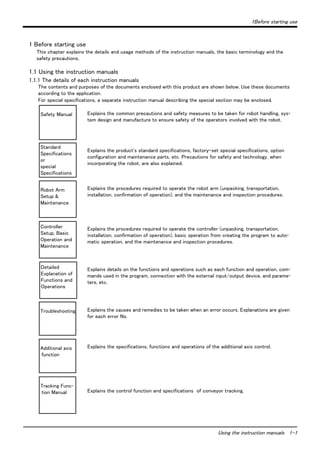
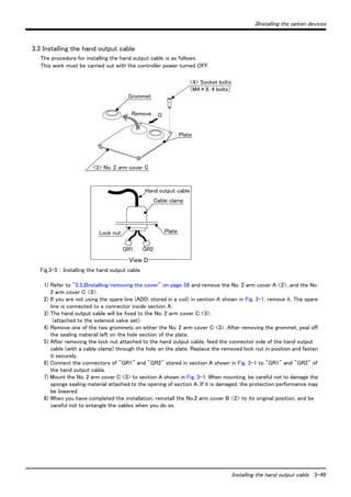
(3) Preparing the T/B
Next, prepare to use the T/B
1) Set the [MODE] switch on the front of the controller to "MANUAL".
2) Set the T/B [ENABLE] switch to "ENABLE". The menu selection
screen will appear.
The following operations are carried out with the T/B.
MODE
MANUAL AUTOMATIC
上:DISABLE
下:ENABLE
*ランプ点灯
T/B背面
Up: Disable
Down: Enable
(Lighting)
◇◆◇ Operating from the T/B ◇◆◇
Always set the [MODE] switch (mode selection key switch) on the front of the controller to "MAMNUAL", and
then set the T/B [ENABLE] switch to "ENABLE".
When the T/B is valid, only operations from the T/B are possible. Operations from the controller or external
signals will not be accepted.](https://image.slidesharecdn.com/bfp-a8653j-141003204745-conversion-gate01/85/Mitsubshi-29-320.jpg)
![2Unpacking to Installation
(4) Selecting the origin setting method
2-22 Setting the origin
1) Press the [4] key on the menu screen, and display the
ORIGIN/BRAKE screen.
2) Press the [1] key on the ORIGIN/BRAKE screen, and
display the origin setting method selection screen.
3) Press the [1] key on the origin setting method selection
screen, and select the data input method.
4) Display the origin data input screen
<MENU>
1.FILE/EDIT 2.RUN
3.PARAM. 4.ORIGIN/BRK
5.SET/INIT. 6.ENHANCED
123 CLOSE
<ORIGIN/BRAKE>
1.ORIGIN 2.BRAKE
123 CLOSE
<ORIGIN>
1.DATA 2.MECH
3.TOOL 4.ABS
5.USER
123 CLOSE
<ORIGIN> DATA
D:(■ )
J1( ) J2( ) J3( )
J4( ) J5( ) J6( )
J7( ) J8( )
123 CLOSE
◇◆◇ Selecting a menu ◇◆◇
The menu can be selected with one of the following methods.
A: Press the numeral key for the No. of the item to be selected.
B: Using the [ ↓ ] and [ ↑ ] keys, etc., move the cursor to the item to be selected, and then press the [INP] key.
◇◆◇ The input method of numeral ◇◆◇
The number can be inputted if the key displayed on the lower left of each key is pressed. Press the
[CHARACTER] key, and in the condition that "123" is displayed on the screen lower side, press the number key.](https://image.slidesharecdn.com/bfp-a8653j-141003204745-conversion-gate01/85/Mitsubshi-30-320.jpg)
![2Unpacking to Installation
Setting the origin 2-23
(5) Inputting the origin data
Input the value confirmed in section "(1) Confirming the
origin data" on page 20.
The correspondence of the origin data label value and axis to
be input is shown in Fig. 2-15.(For the 5-axis robot, the J4
axis is meaningless.)
Origin data label
(D,J1,J2,J3,J4,J5,J6,J7,J8)
Fig.2-15 : Correspondence of origin data label and axis
The method for inputting the origin data is explained below. The value shown in Fig. 2-14 will be input as an
example.
1) Confirm that the cursor is at the "D" position on the T/B
display screen.
2) Input the D value "V!%S29".
Inputting "V"
Press the [CHARACTER] key and set to the character input
mode. (Condition that "ABC" was displayed under the
screen)
Press the [TUV] key three times. "V" will be set.
Inputting "!"
Press the [ , % ] key five times. "!" will be set.
Press the [ → ] key once and advance the cursor.
Press the [ , % ] key twice (input "%"), and press the [PQRS]
key four times (input "S").
Press the [CHARACTER] key and set to the numeral input
mode. (Condition that "123" was displayed under the
screen)
Press the [2] key (input "2"), and press the [9] key (input
"9").
"V!%S29" will appear at the "D" data on the teaching
pendant screen.
3) Press the [ ↓ ] key, and move the cursor to the J1 input
position.
4) Input the J1 value in the same manner as above.
Input the J2, J3, J4, J5 and J6 values in the same manner.
Note that the J4 axis is not required for the 5-axis type.
<ORIGIN> DATA
D:(■ )
J1( ) J2( ) J3( )
J4( ) J5( ) J6( )
J7( ) J8( )
123 CLOSE
T/B screen
,
,
<ORIGIN> DATA
D:(V )
J1( ) J2( ) J3( )
J4( ) J5( ) J6( )
J7( ) J8( )
123 CLOSE
<ORIGIN> DATA
D:(V! )
J1( ) J2( ) J3( )
J4( ) J5( ) J6( )
J7( ) J8( )
123 CLOSE
<ORIGIN> DATA
D:(V!%S29)
J1( ) J2( ) J3( )
J4( ) J5( ) J6( )
J7( ) J8( )
123 CLOSE
<ORIGIN> DATA
D:(V!%S29)
J1( ) J2( ) J3( )
J4( ) J5( ) J6( )
J7( ) J8( )
123 CLOSE
:
:
:
<ORIGIN> DATA
D:(■ )
J1( ) J2( ) J3( )
J4( ) J5( ) J6( )
J7( ) J8( )
123 CLOSE
ABC
ABC](https://image.slidesharecdn.com/bfp-a8653j-141003204745-conversion-gate01/85/Mitsubshi-31-320.jpg)
![2Unpacking to Installation
2-24 Setting the origin
5) After inputting all of the values, press the [EXE] key. The
origin setting confirmation screen will appear.
6) Press [F1] (Yes) to end the origin setting
(6) Installing the shoulder cover A.
Return the shoulder cover A removed in section "(1) Confirming the origin data" on page 20 to its original
position.
This completes the setting of the origin with the origin data input method.
Always remove and install the cover with the controller power turned OFF. Failure
to do so could lead to the robot moving because of incorrect operations, or to
physical damage or personal injury.
<ORIGIN> DATA
D:( V!%S29)
J1( 06DTYY) J2( 2?HL9X) J3( 1CP55V)
J4( T6!MSY) J5( Z21J%Z) J6( A12%Z0)
J7( ) J8( )
ABC CLOSE
<ORIGIN> DATA
CHANGE TO ORIGIN. OK?
Yes 123 No
◇◆◇ Moving the cursor ◇◆◇
Press the [ ↑ ], [ ↓ ], [ ← ] and [ → ] keys.
◇◆◇ Inputting characters ◇◆◇
Press the [CHARACTER] key and set to the character input mode. (Condition that "ABC" was
displayed under the screen). The displayed character is scrolled each time at pressing the key.
◇◆◇ Correcting an input ◇◆◇
After returning one character by pressing the [ C L E A R ] key, input the character again.
WARNING
◇◆◇ If the origin input data is incorrect ◇◆◇
If the origin input data is incorrect, the alarm No. 1760 (origin setting data illegal) will occur when origin data input.
In this case, reconfirm the value input for the origin data.](https://image.slidesharecdn.com/bfp-a8653j-141003204745-conversion-gate01/85/Mitsubshi-32-320.jpg)
![2 Unpacking to Installation
-
Confirming the operation 2-25
2.5 Confirming the operation
In this section, the robot will be moved manually using the T/B to confirm that the operation is correct.
Moving the robot manually is called "jog operation". This operation includes the JOINT jog that moves each axis,
the XYZ jog that moves along the base coordinate system, the TOOL jog that moves along the tool coordinate
system, and the CYLNDER jog that moves along the circular arc.
This operation is carried out while pressing the deadman switch on the back of the T/B.
The robot will move during this operation. Make sure that there are no operators
near the robot, and that there are no obstacles, such as tools, in the robot operation
range.
To immediately stop the robot, release the deadman switch on the back of the T/B.
The servo power will turn OFF, and the robot will stop.
The robot will also stop if the [EMG.STOP] switch (emergency stop switch) on the
front of the T/B or the [EMG.STOP] switch (emergency stop) on the front of the
controller is pressed.
Confirm that the origin has been set. If the origin has not been set, "****" will
appear at the current position display on the teaching pendant, the JOINT jog oper-ation
will take place in any jog mode selected.
Refer to "2.4 Setting the origin" on page 19 for details on setting the origin.
CAUTION
CAUTION
WARNING
-
+
Fig.2-16 : JOINT jog operation
J5 axis
J6 axis
+
-
J1 axis
J4 axis
+
-
J3 axis
+
+
-
J2 axis
-
+
-
+
+
-
J1 axis
J3 axis
-
+
J2 axis
-
+
+
J5 axis
J6 axis
-
5-axis type 6-axis type
* Each axis moves independently.
The 5-axis type does not have the J4 axis.](https://image.slidesharecdn.com/bfp-a8653j-141003204745-conversion-gate01/85/Mitsubshi-33-320.jpg)


![2 Unpacking to Installation
J1 axis jog operation
- X(J1) + X(J1) - X(J1) + X(J1)
- + - +
J1 axis J1 axis
5-axis type 6-axis type
Confirming the operation 2-29
(1) JOINT jog operation
[JOG] Press the key and display the jog screen.
("JOG" is displayed on the screen bottom)
Check that the "joint" in jog mode is displayed on
the screen.
If other jog modes are displayed, please press the
function key corresponding to the "joint." (If the
jog mode which he wishes under the screen is not
displayed, it is displayed that the [FUNCTION]
key is pressed)
If it finishes jog operation, press the [JOG] key
again, or function key which correspond to
"close."
Whenever it presses the key of [OVRD ↑ ], the
override goes up. Conversely, if the [OVRD ↓ ]
key is pressed, it will go down.
The current setting speed is displayed on screen
upper right, and "STATUS NUMBER" of the
controller.
Set the override to 10% here for confirmation
work
Select joint jog mode
<CURRENT> JOINT 100% M1 T0
J1: +0.00 J5: +0.00
J2: +0.00 J6: +0.00
J3: +90.00 :
J4: +0.00 :
XYZ TOOL JOG 3-XYZ CYLNDR ⇒
Set jog speed
Joint jog mode
<CURRENT> JOINT 100% M1 T0
J1: +0.00 J5: +0.00
J2: +0.00 J6: +0.00
J3: +90.00 :
J4: +0.00 :
XYZ TOOL JOG 3-XYZ CYLNDR ⇒
Setting the speed
・When the [+X (J1)] keys are pressed, the J1 axis will rotate in the plus direction.
When the [-X (J1)] keys are pressed, Rotate in the minus direction.
- Y(J2)
J2 axis jog operation
J2 axis J2 axis
+ Y(J2)
5-axis type 6-axis type
- Y(J2)
+ Y(J2)](https://image.slidesharecdn.com/bfp-a8653j-141003204745-conversion-gate01/85/Mitsubshi-37-320.jpg)
![2 Unpacking to Installation
・When the [+Y (J2)] keys are pressed, the J2 axis will rotate in the plus direction.
When the [-Y (J2)] keys are pressed, Rotate in the minus direction.
◇◆◇ When the robot is in the transportation posture ◇◆◇
The axes may be outside the movement area. Move these axes toward the inner side of the movement area.
5-axis type 6-axis type
J3 axis
・When the [+Z (J3)] keys are pressed, the J3 axis will rotate in the plus direction.
When the [-Z (J3)] keys are pressed, Rotate in the minus direction.
+C(J6)
-B(J5)
- C(J6) J4 axis
J4, J5 and J6 axis jog operation
+C(J6)
-B(J5)
・When the [+A (J4)] keys are pressed, the J4 axis will rotate in the plus direction.
When the [-A (J4)] keys are pressed, Rotate in the minus direction. (6-axis type only)
・When the [+B (J5)] keys are pressed, the J5 axis will rotate in the plus direction
When the [-B (J5)] keys are pressed, Rotate in the minus direction.
・When the [+C (J6)] keys are pressed, the J6 axis will rotate in the plus direction
When the [-C (J6)] keys are pressed, Rotate in the minus direction.
2-30 Confirming the operation
J3 axis
- Z(J3)
+ Z(J3)
- Z(J3)
+ Z(J3)
J3 axis jog operation
5-axis type 6-axis type
-
+
+
-
J6 axis
J5 axis
+
-
-
+
+
-
J6 axis
J5 axis
+B(J5)
+A(J4)
-A(J4)
- C(J6)
+B(J5)
◇◆◇If the buzzer of T/B sounds and the robot does not move ◇◆◇
If it is going to move the robot across the operation range, the buzzer of T/B sounds and the robot does not
move. In this case, please move to the counter direction.](https://image.slidesharecdn.com/bfp-a8653j-141003204745-conversion-gate01/85/Mitsubshi-38-320.jpg)
![2 Unpacking to Installation
+Z
-Y -X
+X +Y
-Z
-Y -X
+X +Y
- Y(J2)
+ Z(J3)
5-axis type 6-axis type
Confirming the operation 2-31
(2) XYZ jog operation
[JOG] Press the key and display the jog screen.
("JOG" is displayed on the screen bottom)
Check that the "XYZ" in jog mode is displayed on
the screen.
If other jog modes are displayed, please press the
function key corresponding to the "XYZ." (If the
jog mode which he wishes under the screen is not
displayed, it is displayed that the [FUNCTION]
key is pressed)
If it finishes jog operation, press the [JOG] key
again, or function key which correspond to
"close."
Whenever it presses the key of [OVRD ↑ ], the
override goes up. Conversely, if the [OVRD ↓ ]
key is pressed, it will go down.
The current setting speed is displayed on screen
upper right, and "STATUS NUMBER" of the
controller.
Set the override to 10% here for confirmation
work
Select XYZ jog mode
<CURRENT> JOINT 100% M1 T0
J1: +0.00 J5: +0.00
J2: +0.00 J6: +0.00
J3: +90.00 :
J4: +0.00 :
XYZ TOOL JOG 3-XYZ CYLNDR ⇒
Set jog speed
XYZ jog mode
<CURRENT> JOINT 100% M1 T0
J1: +0.00 J5: +0.00
J2: +0.00 J6: +0.00
J3: +90.00 :
J4: +0.00 :
XYZ TOOL JOG 3-XYZ CYLNDR ⇒
Setting the speed
- Y(J2)
+ Z(J3)
・When the [+X (J1)] keys are pressed, the robot will move along the X axis plus direction.
When the [-X (J1)] keys are pressed, Move along the minus direction.
・When the [+Y (J2)] keys are pressed, the robot will move along the Y axis plus direction.
When the [-Y (J2)] keys are pressed, Move along the minus direction.
・When the [+Z (J3)] keys are pressed, the robot will move along the Z axis plus direction.
When the [-Z (J3)] keys are pressed, Move along the minus direction.
+Z
-Z
+X
+Y
+Z
Tool length
+X
+Y
+Z
Tool length
- X(J1)
+ X(J1)
+ Y(J2)
- Z(J3)
- X(J1)
+ X(J1)
+ Y(J2)
- Z(J3)
Moving along the base coordinate system
* The direction of the flange will not change
◇◆◇ When the robot is in the transportation posture ◇◆◇
There are directions from which linear movement is not possible from the transportation posture. In this case, the
robot will not move. Refer to section "(1) JOINT jog operation" on page 29", and move the robot to a position
where linear movement is possible, and then carry out XYZ jog.](https://image.slidesharecdn.com/bfp-a8653j-141003204745-conversion-gate01/85/Mitsubshi-39-320.jpg)
![2 Unpacking to Installation
◇◆◇If the buzzer of T/B sounds and the robot does not move ◇◆◇
If it is going to move the robot across the operation range, the buzzer of T/B sounds and the robot does not
move. In this case, please move to the counter direction.
+Z
-
-Y -X
+X +Y
-Z
+Z
-
-Y -X
+X +Y
- +
Control point
(Tool coordinate system)
・When the [+A (J4)] keys are pressed,
6-axis type: The X axis will rotate in the plus direction.
5-axis type: The Z axis will rotate in the plus direction of the tool coordinate system.
When the [-A (J4)] keys are pressed, Rotate in the minus direction.
・When the [+B (J5)] keys are pressed,
6-axis type: The Y axis will rotate in the plus direction.
5-axis type: The Y axis will rotate in the plus direction of the tool coordinate system.
When the [-B (J5)] keys are pressed, Rotate in the minus direction.
・When the [+C (J6)] keys are pressed,
6-axis type: The Z axis will rotate in the plus direction.
5-axis type: There is no operation.
When the [-C (J6)] keys are pressed,
6-axis type: Rotate in the minus direction.
5-axis type: There is no operation.
2-32 Confirming the operation
-Z
5-axis type 6-axis type
+Y
+
-
+
+X
+Z
+
- +
+Y
Control point
Tool length
+Z
Tool length
- C(J6) +C(J6)
+B(J5)
-B(J5)
+A(J4)
-A(J4)
+B(J5)
-B(J5)
+A(J4)
-A(J4)
Changing the flange surface posture
* The control point does not change.
◇◆◇ When alarm No. 5150 occurs ◇◆◇
If alarm No. 5150 (ORIGIN NOT SET) occurs, the origin has not been set correctly. Reconfirm the value input for
the origin data.
◇◆◇ Tool length ◇◆◇
The default tool length is 0mm, and the control point is the center of the end axis.
After installing the hand, set the correct tool length in the parameters. Refer to the separate manual "Detailed
Explanation of Functions and Operations" for details.](https://image.slidesharecdn.com/bfp-a8653j-141003204745-conversion-gate01/85/Mitsubshi-40-320.jpg)
![2 Unpacking to Installation
- Z(J3)
+Y
+X
- X(J1)
+Z
Tool length
Control point
+ Y(J2)
+ X(J1)
- Y(J2)
+ Z(J3)
Moving along the tool coordinate system
5-axis type 6-axis type
* The direction of the flange will not change
Confirming the operation 2-33
(3) TOOL jog operation
[JOG] Press the key and display the jog screen.
("JOG" is displayed on the screen bottom)
Check that the "TOOL" in jog mode is displayed
on the screen.
If other jog modes are displayed, please press the
function key corresponding to the "TOOL." (If
the jog mode which he wishes under the screen is
not displayed, it is displayed that the [FUNC-TION]
key is pressed)
If it finishes jog operation, press the [JOG] key
again, or function key which correspond to
"close."
Whenever it presses the key of [OVRD ↑ ], the
override goes up. Conversely, if the [OVRD ↓ ]
key is pressed, it will go down.
The current setting speed is displayed on screen
upper right, and "STATUS NUMBER" of the
controller.
Set the override to 10% here for confirmation
work
Select TOOL jog mode
<CURRENT> JOINT 100% M1 T0
J1: +0.00 J5: +0.00
J2: +0.00 J6: +0.00
J3: +90.00 :
J4: +0.00 :
XYZ TOOL JOG 3-XYZ CYLNDR ⇒
Set jog speed
TOOL jog mode
<CURRENT> JOINT 100% M1 T0
J1: +0.00 J5: +0.00
J2: +0.00 J6: +0.00
J3: +90.00 :
J4: +0.00 :
XYZ TOOL JOG 3-XYZ CYLNDR ⇒
~
Setting the speed
- Z(J3)
+Y
+X
- X(J1)
+Z
Tool length
Control point
+ Z(J3)
+ X(J1)
・When the [+X (J1)] keys are pressed, the robot will move along the X axis plus direction of the tool coordinate
system.
When the [-X (J1)] keys are pressed, Move along the minus direction.
・When the [+Y (J2)] keys are pressed, the robot will move along the Y axis plus direction of the tool coordinate
system.
When the [-Y (J2)] keys are pressed, Move along the minus direction. (6-axis type only)
・When the [+Z (J3)] keys are pressed, the robot will move along the Z axis plus direction of the tool coordinate
system.
When the [-Z (J3)] keys are pressed, Move along the minus direction.
◇◆◇ When the robot is in the transportation posture ◇◆◇
There are directions from which linear movement is not possible from the transportation posture. In this case, the
robot will not move. Refer to section "(1) JOINT jog operation" on page 29", and move the robot to a position
where linear movement is possible, and then carry out XYZ jog.](https://image.slidesharecdn.com/bfp-a8653j-141003204745-conversion-gate01/85/Mitsubshi-41-320.jpg)
![2 Unpacking to Installation
◇◆◇If the buzzer of T/B sounds and the robot does not move ◇◆◇
If it is going to move the robot across the operation range, the buzzer of T/B sounds and the robot does not
move. In this case, please move to the counter direction.
Changing the flange surface posture
-
+
-
-B(J5)
+Y
-
+
+
+X
+Z
5-axis type 6-axis type
Control point
・When the[+A (J4)] keys are pressed,
6-axis type: The X axis will rotate in the plus direction of the tool coordinate system.
5-axis type: There is no operation.
When the[-A (J4)] keys are pressed,
6-axis type: Rotate in the minus direction.
5-axis type: There is no operation.
・When the[+B (J5)] keys are pressed,
6-axis type: The Y axis will rotate in the plus direction of the tool coordinate system.
5-axis type: The J5 axis will rotate in the plus direction.
When the[-B (J5)] keys are pressed, Rotate in the minus direction.
・When the[+C (J6)] keys are pressed,
6-axis type: The Z axis will rotate in the plus direction of the tool coordinate system.
5-axis type: The J6 axis will rotate in the plus direction.
When the[-C (J6)] keys are pressed, Rotate in the minus direction.
2-34 Confirming the operation
* The control point does not change.
-
+
-
+
+Z
+Y
(Tool coordinate system)
Tool length
Tool length
- C(J6)
+C(J6)
+B(J5)
+A(J4)
-A(J4)
+C(J6)
- C(J6)
-B(J5)
+B(J5)
◇◆◇ When alarm No. 5150 occurs ◇◆◇
If alarm No. 5150 (ORIGIN NOT SET) occurs, the origin has not been set correctly. Reconfirm the value input for
the origin data.
◇◆◇ Tool length ◇◆◇
The default tool length is 0mm, and the control point is the center of the end axis.
After installing the hand, set the correct tool length in the parameters. Refer to the separate manual "Detailed
Explanation of Functions and Operations" for details.](https://image.slidesharecdn.com/bfp-a8653j-141003204745-conversion-gate01/85/Mitsubshi-42-320.jpg)
![2 Unpacking to Installation
+Z
-Y -X
+X +Y
-Z
-Y -X
+X +Y
- Y(J2)
+ Z(J3)
5-axis type 6-axis type
Confirming the operation 2-35
(4) 3-axis XYZ jog operation
[JOG] Press the key and display the jog screen.
("JOG" is displayed on the screen bottom)
Check that the "XYZ456" in jog mode is
displayed on the screen.
If other jog modes are displayed, please press the
function key corresponding to the "XYZ456." (If
the jog mode which he wishes under the screen is
not displayed, it is displayed that the [FUNC-TION]
key is pressed)
If it finishes jog operation, press the [JOG] key
again, or function key which correspond to
"close."
Whenever it presses the key of [OVRD ↑ ], the
override goes up. Conversely, if the [OVRD ↓ ]
key is pressed, it will go down.
The current setting speed is displayed on screen
upper right, and "STATUS NUMBER" of the
controller.
Set the override to 10% here for confirmation
work
Select XYZ456 jog mode
<CURRENT> JOINT 100% M1 T0
J1: +0.00 J5: +0.00
J2: +0.00 J6: +0.00
J3: +90.00 :
J4: +0.00 :
XYZ TOOL JOG 3-XYZ CYLNDR ⇒
Set jog speed
XYZ456 jog mode
<CURRENT> JOINT 100% M1 T0
J1: +0.00 J5: +0.00
J2: +0.00 J6: +0.00
J3: +90.00 :
J4: +0.00 :
XYZ TOOL JOG 3-XYZ CYLNDR ⇒
~
Setting the speed
- Y(J2)
+ Z(J3)
・When the[+X (J1)] keys are pressed, the robot will move along the X axis plus direction.
When the[-X (J1)] keys are pressed, Move along the minus direction.
・When the[+Y (J2)] keys are pressed, the robot will move along the Y axis plus direction.
When the[-Y (J2)] keys are pressed, Move along the minus direction.
・When the[+Z (J3)] keys are pressed, the robot will move along the Z axis plus direction.
When the[-Z (J3)] keys are pressed, Move along the minus direction.
+Z
-Z
+X
+Y
+Z
Tool length
+X
+Y
+Z
Tool length
- X(J1)
+ X(J1)
+ Y(J2)
- Z(J3)
- X(J1)
+ X(J1)
+ Y(J2)
- Z(J3)
Moving along the base coordinate system
* The direction of the flange will change
◇◆◇ The flange surface end axis posture cannot be maintained with 3-axis XYZ jog. ◇◆◇
With 3-axis XYZ jog, the flange surface end axis posture (orientation) is not maintained when moving linearly in
the X, Y or Z axis direction.
Use XYZ jog to maintain the posture.](https://image.slidesharecdn.com/bfp-a8653j-141003204745-conversion-gate01/85/Mitsubshi-43-320.jpg)
![2 Unpacking to Installation
+C(J6)
-B(J5)
- C(J6) J4 axis
+C(J6)
-B(J5)
・When the[+A (J4)] keys are pressed, the J4-axis will rotate in the plus direction.
At this time, to maintain the flange's position, other axes move simultaneously except J5 and J6.
When the[-A (J4)] keys are pressed, Rotate in the minus direction. (6-axis type only)
・When the[+B (J5)] keys are pressed, the J5-axis will rotate in the plus direction.
At this time, to maintain the flange's position, other axes move simultaneously except J4 and J6.
When the[-B (J5)] keys are pressed, Rotate in the minus direction.
・When the[+C (J6)] keys are pressed, the J6-axis will rotate in the plus direction.
When the[-C (J6)] keys are pressed, Rotate in the minus direction.
2-36 Confirming the operation
5-axis type 6-axis type
-
+
+
-
J6 axis
J5 axis
+
-
-
+
+
-
J6 axis
J5 axis
+B(J5)
+A(J4)
-A(J4)
- C(J6)
+B(J5)
* The flange position changes.
This is the same as the J4, J5 and J6 axis JOINT jog operation.
Changing the flange surface posture](https://image.slidesharecdn.com/bfp-a8653j-141003204745-conversion-gate01/85/Mitsubshi-44-320.jpg)
![2 Unpacking to Installation
Moving along an arc centering on the Z axis
+Z
- X(J1)
+ Y(J2)
-Y -X
+ Z(J3)
- Y(J2)
Arc
+X +Y
-Z
+Z
- X(J1)
+ Y(J2)
-Y -X
+ Z(J3)
- Y(J2)
Arc
+X +Y
-Z
Vertical
Tool length
Radius
+ X(J1)
Control point
- Z(J3)
5-axis type 6-axis type
* The direction of the frange will not change.
Confirming the operation 2-37
(5) CYLNDER jog operation
[JOG] Press the key and display the jog screen.
("JOG" is displayed on the screen bottom)
Check that the "CYLNDER" in jog mode is
displayed on the screen.
If other jog modes are displayed, please press the
function key corresponding to the "CYLNDER."
(If the jog mode which he wishes under the
screen is not displayed, it is displayed that the
[FUNCTION] key is pressed)
If it finishes jog operation, press the [JOG] key
again, or function key which correspond to
"close."
Whenever it presses the key of [OVRD ↑ ], the
override goes up. Conversely, if the [OVRD ↓ ]
key is pressed, it will go down.
The current setting speed is displayed on screen
upper right, and "STATUS NUMBER" of the
controller.
Set the override to 10% here for confirmation
work
Select cylindrical jog mode
<CURRENT> JOINT 100% M1 T0
J1: +0.00 J5: +0.00
J2: +0.00 J6: +0.00
J3: +90.00 :
J4: +0.00 :
XYZ TOOL JOG 3-XYZ CYLNDR ⇒
Set jog speed
CYLNDER jog mode
<CURRENT> JOINT 100% M1 T0
J1: +0.00 J5: +0.00
J2: +0.00 J6: +0.00
J3: +90.00 :
J4: +0.00 :
XYZ TOOL JOG 3-XYZ CYLNDR ⇒
~
Setting the speed
Vertical
Tool length
Radius
+ X(J1)
Control point
- Z(J3)
Assuming that the current position is on an arc centering on the Z axis, the robot moves along that arc.
・When the[+X (J1)] keys are pressed, the robot will expand in the radial direction.
When the[-X (J1)] keys are pressed, Contract in the radial direction.
・When the[+Y (J2)] keys are pressed, the robot will move along the arc in the plus direction.
When the[-Y (J2)] keys are pressed, Move in the minus direction.
・When the[+Z (J3)] keys are pressed, the robot will move along the Z axis plus direction.
When the[-Z (J3)] keys are pressed, Move along the minus direction.](https://image.slidesharecdn.com/bfp-a8653j-141003204745-conversion-gate01/85/Mitsubshi-45-320.jpg)
![2 Unpacking to Installation
+Z
-
-Y -X
+X +Y
-Z
+Z
-
- B
(J5)
+ C
(J6)
+ B
(J5)
-Y -X
+X +Y
Control point
(Tool coordinate system)
- +
- C
+ (J6)
+ A
(J4)
- A
(J4)
・When the [+A (J4)] keys are pressed,
6-axis type: The X axis will rotate in the plus direction.
5-axis type: The Z axis will rotate in the plus direction of the tool coordinate system.
When the [-A (J4)] keys are pressed, Rotate in the minus direction.
・When the [+B (J5)] keys are pressed,
6-axis type: The Y axis will rotate in the plus direction.
5-axis type: The Y axis will rotate in the plus direction of the tool coordinate system.
When the [-B (J5)] keys are pressed, Rotate in the minus direction.
・When the [+C (J6)] keys are pressed,
6-axis type: The Z axis will rotate in the plus direction.
5-axis type: There is no operation.
When the [-C (J6)] keys are pressed,
6-axis type: Rotates in the minus direction.
5-axis type: There is no operation.
2-38 Confirming the operation
-Z
5-axis type 6-axis type
+Y
+
-
+
+Z
Tool length
+B(J5)
-B(J5)
+A(J4)
-A(J4)
+X
+Z
+
- +
+Y
STEP
MO VE
0 ABC
7 YZ_
STEP
MO VE
+
2 GHI
STEP
MO VE
+
1 DEF
STEP
MOVE
+
6 VWX
STEP
MOVE
+
5 STU
STEP
MO VE
+
Tool length
Control point
Changing the flange surface posture
* The flange position does not change.
This is the same as the A, B and C axis XYZ jog operation.](https://image.slidesharecdn.com/bfp-a8653j-141003204745-conversion-gate01/85/Mitsubshi-46-320.jpg)
![2 Unpacking to Installation
Robot coordinates
system
Confirming the operation 2-39
(6) Work jog operation
Setting of the work coordinates system is necessary.
By this jog operation, robot can be move along with the direction of work (or working table etc.), so teaching
operations get easier.
When jog operation, select by which work coordinates the robot moves
The setting method of the work coordinates system using T/B (R32TB) is shown in the following.
(Parameter: Setting the coordinate value to WKnCORD ("n" is meaning the number (1-8) of work
coordinates) can also set up the work coordinates system. Refer to the separate manual "Detailed
Explanation of Functions and Operations" for details of parameter.)
In addition, this jog operation is available at the following software versions. The below-mentioned
"6.ENHANCED" menu is not displayed in the other versions.
T/B :Ver.1.3 or later
SQ series: N8 or later
SD series :P8 or later
The work coordinates system teaches and sets up the three points (WO, WX, WY).
+Zw
+Xw
+Yw
+Z
work coordinates
WO
Fig.2-22 : Setting of the work coordinates system (teaching point)
The setting (definition) method of the work coordinates system is shown in the following.
+Y
+X
< Teaching point>
WO: Work coordinates system origin
WX: Position on the "+X" axis of work coordinates system.
WY: Position at the side of "+Y" axis on the X-Y plane of work coordinates system
Work
WY
WX
Notes) The figure is the example of
RV-6SD, but other types are
the same
The jogging movement
based on this work is
possible.
[Supplement] : The coordinate values which use all three teaching points for setting of the
work coordinates system are each only X, Y, and the Z-axis. Although the coor-dinate
value of A, B, and C axis is not used, positioning will get easy if the XYZ
jog or TOOL jog movement is effected with the same value. (The direction of the
hand is the same)](https://image.slidesharecdn.com/bfp-a8653j-141003204745-conversion-gate01/85/Mitsubshi-47-320.jpg)
![2 Unpacking to Installation
1) Select "6.ENHANCED" screen on the <MENU> screen.
<MENU>
1.FILE/EDIT 2.RUN
3.PARAM. 4.ORIGIN/BRK
5.SET/INIT. 6.ENHANCED
123 CLOSE
2) Press the [2] keys in the menu screen and select "2. xxxxx."
3) Selection of the work coordinates number
Press the [FUNCTION] keys, and display "W: JUMP" function. Press the function key corresponding to
"W: JUMP"
Press numeral key [1] - [8] and specify the work coordinates number. The coordinate value of the specified
work coordinates system is displayed.
4) The teaching of the work coordinates system
Teach the three points shown in Fig. 2-22. Confirm the name currently displayed on the "TEACHING
POINT" at the upper right of the screen. If it differs, press the function key corresponding to each
point(WO, WX, WY) to teach. Move the robot's arm by jog operation (other jogging movement), and press
the function key corresponding to "TEACH."([F1]) The confirmation screen is displayed.
2-40 Confirming the operation
<EMHANCED>
1.SQ DIRECT 2.WORK COORD.
123 CLOSE
The screen shows the coordinate value of the origin
(WO) of the work coordinates number 1.
<EMHANCED>
1.SQ DIRECT 2.WORK COORD.
123 CLOSE
<WORK COORD> WORK NUMBER (1)
TEACHING POINT (WO)
X: 0.00
Y: 0.00
Z: 0.00
TEACH WX 123 WY DEFINE
<WORK COORD> WORK NUMBER (1)
TEACHING POINT (WO)
X: 0.00
Y: 0.00
Z: 0.00
W.JUMP W.GRID 123 CLOSE
<WORK JUMP>
CHOOSE ONE OF THE WORK NUMBER
1-8.
123 CLOSE
The screen is the example which specified
the work coordinates number 2. ("2" at the
upper right of the screen)
Operation will be canceled if the
[CLOSE] key is pressed.
<WORK JUMP>
CHOOSE ONE OF THE WORK NUMBER
1-8.
123 CLOSE
<WORK COORD> WORK NUMBER (2)
TEACHING POINT (WO)
X: 0.00
Y: 0.00
Z: 0.00
W.JUMP W.GRID 123 CLOSE
<WORK COORD> WORK NUMBER (2)
TEACHING POINT (WO)
X: 0.00
Y: 0.00
Z: 0.00
TEACH WX 123 WY DEFINE
Specify the teaching point [WO],[WX],[WY]
teaching the position [TEACH]
<WORK COORD> WORK NUMBER (2)
TEACHING POINT (WO)
RECORD CURRENT POSITION.
OK?
Yes 123 No](https://image.slidesharecdn.com/bfp-a8653j-141003204745-conversion-gate01/85/Mitsubshi-48-320.jpg)
![2 Unpacking to Installation
Presses the function key corresponding to"Yes", the robot's current position is registered, and the
registered coordinates value is displaye. Operation will be canceled if the [CLOSE] key is pressed.
<WORK COORD> WORK NUMBER (2)
TEACHING POINT (WO)
RECORD CURRENT POSITION.
OK?
Yes 123 No
<WORK COORD> WORK NUMBER (2)
TEACHING POINT (WO)
X: 214.12
Y: -61.23
Z: 553.30
W.JUMP W.GRID 123 CLOSE
Teach the three points, WO, WX, and WY, by the same operation.
The position data taught here is each registered into the following parameters. ("n" means the work coor-dinates
<WORK COORD> WORK NUMBER (2)
WORK COORDINATES DATA
(3.53, -220.00, 5.14, 0.00, 0.
123 CLOSE
<WORK COORD> WORK NUMBER (2)
TEACHING POINT (WO)
TEACH WX 123 WY DEFINE
Confirming the operation 2-41
numbers 1-8)
WO= parameter: WKnWO
WX= parameter: WKnWX
WY= parameter: WKnWY
5) Setting of work coordinates (definition)
If the function key corresponding to "DEFINE" ([F1]) is pressed, the work coordinates system will be
calculated using the three points, and the result will be displayed.
<WORK COORD> WORK NUMBER (2)
TEACHING POINT (WO)
X: 214.12
Y: -61.23
Z: 553.30
TEACH WX 123 WY DEFINE
00, 0.00)
The alarm occurs if the work coordinates system is incalculable. (There are the three points on the straight
line, or the two points have overlapped) In this case, reset alarm and re-teach the three points.
This work coordinate data is registered into parameter: WKnCORD. ("n" means the work coordinates
numbers 1-8)
If the function key corresponding to "CLOSE" is pressed, it will return to the previous screen.
<WORK COORD> WORK NUMBER (2)
WORK COORDINATES DATA
(3.53, -220.00, 5.14, 0.00, 0.
00, 0.00)
123 CLOSE
6) Finishing of setting the work coordinates
X: 214.12
Y: -61.23
Z: 553.30
Press the [FUNCTION] keys, and display "CLOSE" function. Press the function key corresponding to
"CLOSE". Returns to the <MENU> screen.
<WORK COORD> WORK NUMBER (2)
TEACHING POINT (WO)
X: 214.12
Y: -61.23
Z: 553.30
W.JUMP W.GRI D 123 CLOSE
<EMHANCED>
1.SQ DIRECT 2.WORK COORD.
123 CLOSE](https://image.slidesharecdn.com/bfp-a8653j-141003204745-conversion-gate01/85/Mitsubshi-49-320.jpg)
![2 Unpacking to Installation
Although setting of work coordinates is finishing above, confirmation of work coordinates can be done by press-ing
the function key corresponding to "W GRID."([F2])
Then, the operation method of the work jog is shown.
Change to the work jog after nearing the work.
<CURRENT> WORK 100% M1 T0 W1
J1: +0.00 J5: +0.00
J2: +0.00 J6: +0.00
J3: +90.00 :
J4: +0.00 :
XYZ TOOL JOG 3-XYZ CYLNDR ⇒
<CURRENT> WORK 100% M1 T0 W1
J1: +0.00 J5: +0.00
J2: +0.00 J6: +0.00
J3: +90.00 :
J4: +0.00 :
XYZ TOOL JOG 3-XYZ CYLNDR ⇒
<CURRENT> JOINT 100% M1 T0
J1: +0.00 J5: +0.00
J2: +0.00 J6: +0.00
J3: +90.00 :
J4: +0.00 :
XYZ TOOL JOG 3-XYZ CYLNDR ⇒
2-42 Confirming the operation
Return to the previous screen by pressing
the [CLOSE] ([F4]) key.
[JOG] Press the key and display the jog
screen. ("JOG" is displayed on the screen
bottom)
Check that the "WORK" in jog mode is
displayed on the screen.
If other jog modes are displayed, please press
the function key corresponding to the "WORK."
(If the jog mode which he wishes under the
screen is not displayed, it is displayed that the
[FUNCTION] key is pressed)
If it finishes jog operation, press the [JOG] key
again, or function key which correspond to
"close."
Confirm the target work coordinates system.
The current target number is displayed on the
screen upper right. (W1Å`W8)
The number of work coordinates can be
changed by the arrow key [Upper arrow],
[Lower arrow]
Push the key [Upper arrow], the number will
increase. (W1, W2, ..... W8) Conversely, push
the key [Lower arrow], the number will
decrease
~
Target work
coordinates system
Always confirm that the number of the target work coordinates system is displayed
correctly (Display of W1-W8 at the upper right of the screen)
If mistaken, the robot will move in the direction which is not meant and will cause the
damage and the personal injuries.
Whenever it presses the key of [OVRD(Upper
arrow)], the override goes up. Conversely, if
the [OVRD(Lower arrow)] key is pressed, it will
go down.
The current setting speed is displayed on
screen upper right, and "STATUS NUMBER" of
the controller.
Set the override to 10% here for confirmation
work
<WORK COORD> WORK NUMBER (2)
TEACHING POINT (WO)
X: 214.12
Y: -61.23
Z: 553.30
W.JUMP W.GRI D 123 CLOSE
<WORK COORD> WORK NUMBER (2)
WORK COORDINATES DATA
(3.53, -220.00, 5.14, 0.00, 0.
00, 0.00)
123 CLOSE
Select WORK jog mode
WORK jog mode
Confirmation and selection of the
work coordinates system
Select the work coordinates system
CAUTION
Set jog speed
Setting the speed](https://image.slidesharecdn.com/bfp-a8653j-141003204745-conversion-gate01/85/Mitsubshi-50-320.jpg)
![2 Unpacking to Installation
+Z
-Y -X
+Z
-Y -X
Tool length
Controll point
Work coordinates system Work coordinates system
・When the[+X (J1)] keys are pressed, the robot will move along the X axis plus direction on the work
coordinates system.
When the[-X (J1)] keys are pressed, Move along the minus direction.
・When the[+Y (J2)] keys are pressed, the robot will move along the Y axis plus direction on the work
coordinates system.
When the[-Y (J2)] keys are pressed, Move along the minus direction.
・When the[+Z (J3)] keys are pressed, the robot will move along the Z axis plus direction on the work
coordinates system.
When the[-Z (J3)] keys are pressed, Move along the minus direction.
Confirming the operation 2-43
5軸タイプ
6軸タイプ
+X +Y
-Z
+X +Y
-Z
ツール長
+Xw
+Yw
+Zw
ツール長
+Xw
+Yw
+Zw
制御点
制御点
The jog movement based on work coordinates system
* The direction of the flange will not
change. Move the control point
with a straight line in accordance
with the work coordinates system
Tool length
Controll point
5 axis type 6 axis type](https://image.slidesharecdn.com/bfp-a8653j-141003204745-conversion-gate01/85/Mitsubshi-51-320.jpg)
![2 Unpacking to Installation
+Z
-
-Y -X
+X +Y
-Z
Tool length
ツール長
Controll point
Work coordinates system Work coordinates system
・When the[+A (J4)] keys are pressed,
6-axis type: The X axis will rotate in the plus direction of the work coordinate system.
5-axis type: There is no operation.
When the[-A (J4)] keys are pressed,
6-axis type: Rotate in the minus direction.
5-axis type: There is no operation.
・When the [+B (J5)] keys are pressed,
6-axis type: The Y axis will rotate in the plus direction of the work coordinate system..
5-axis type: The Y axis will rotate in the plus direction of the tool coordinate system.
When the [-B (J5)] keys are pressed, Rotate in the minus direction.
・When the [+C (J6)] keys are pressed,
6-axis type: The Z axis will rotate in the plus direction of the work coordinate system...
5-axis type: There is no operation.
When the [-C (J6)] keys are pressed,
6-axis type: Rotate in the minus direction.
5-axis type: There is no operation.
2-44 Confirming the operation
+Z
-Y
+X +Y
-Z
5軸タイプ6軸タイプ
-X
ツール長
+Xw
+Yw
+Zw
+
-
+
-
-
+Xw +
+Yw
+Zw
+
-
+
+Z
+Y
制御点
制御点
Changing the flange surface posture
* The position of the control point does not change.
Change the direction of the flange in accordance with
the work coordinates system. (6 axis type)
Tool length
Controll point
5 axis type 6 axis type
◇◆◇ When the robot is in the transportation posture ◇◆◇
There are directions from which linear movement is not possible from the transportation posture. In this case, the
robot will not move. Refer to section "(1) JOINT jog operation" on page 29", and move the robot to a position
where linear movement is possible, and then carry out XYZ jog.
◇◆◇If the buzzer of T/B sounds and the robot does not move ◇◆◇
If it is going to move the robot across the operation range, the buzzer of T/B sounds and the robot does not
move. In this case, please move to the counter direction.
◇◆◇ Tool length ◇◆◇
The default tool length is 0mm, and the control point is the center of the end axis.
After installing the hand, set the correct tool length in the parameters. Refer to the separate manual "Detailed
Explanation of Functions and Operations" for details.](https://image.slidesharecdn.com/bfp-a8653j-141003204745-conversion-gate01/85/Mitsubshi-52-320.jpg)


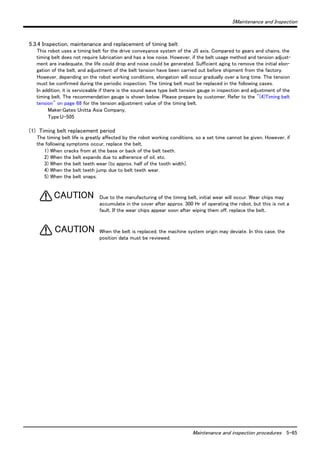
![5Maintenance and Inspection
1,000 Hr Monthly inspection 3-month inspection 6-month inspection
2,000 Hr Monthly inspection 3-month inspection 6-month inspection Yearly inspection
4,000 Hr Monthly inspection 3-month inspection 6-month inspection Yearly inspection 2-year inspection
8 Hr/day × 20 days/month × 3 months = approx. 500 Hr
10 Hr/day × 20 days/month × 3 months = approx. 600 Hr
15 Hr/day × 20 days/month × 3 months = approx. 1000 Hr
[Caution] When using two lines, the 3-month inspection, 6-month inspection and yearly
inspection must be carried out when half the time has passed.
Maintenance and inspection interval 5-53
5 Maintenance and Inspection
The maintenance and inspection procedures to be carried out to use the robot for a long time without trouble are
described in this chapter. The types and replacement methods of consumable parts are also explained.
5.1 Maintenance and inspection interval
Maintenance and inspection are divided into the inspections carried out daily, and the periodic inspections carry
out at set intervals. Always carry these out to prevent unforeseen trouble, to maintain the product for a long time,
and to secure safety.
(1) Inspection schedule
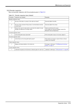
In addition to the monthly inspection, add the following inspection items every three months (estimated at 500 Hr
operation hours).
0 Hr
500 Hr Monthly inspection 3-month inspection
Daily inspection
Monthly inspection
Monthly inspection
Monthly inspection
Monthly inspection
Monthly inspection
Monthly inspection
1,500 Hr Monthly inspection 3-month inspection
Monthly inspection
Monthly inspection
Operating time
<Guideline for inspection period>
For one shift
For two shifts
Fig.5-1 : Inspection schedule](https://image.slidesharecdn.com/bfp-a8653j-141003204745-conversion-gate01/85/Mitsubshi-61-320.jpg)


![5Maintenance and Inspection
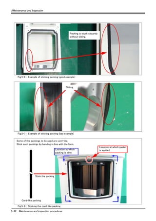
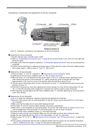
A 1mm overlap
[2] Apply liqu [1] Cut the packing so that there is a 1mm overlap at id gasket to the cut edges.
Maintenance and inspection procedures 5-63
Join by liquid gasket
the end.
[3] Stick the packing so that there is no gap between the
adjacent pieces.
Fig.5-9 : Examples of packing overlaps
ガスケットを塗布していない
パッキンが接触していない
パッキンがずれている
パッキンが重なっている
パッキンの切断面が乱れている
パッキンが斜めに切断されている
Unsuitable overlap of packing
Gasket is not applied.
Ends of packing are not in contact with each
other.
Displacement at the ends of packing
Ends of packing overlap each other.
Cut edge of packing is irregular.
End of packing is cut diagonally.](https://image.slidesharecdn.com/bfp-a8653j-141003204745-conversion-gate01/85/Mitsubshi-71-320.jpg)


![5Maintenance and Inspection
The lubrication specifications for each place are shown in Fig. 5-6.
[Caution]
・The brands of grease given in Table 5-6 are those filled when the robot is shipped.
・The lubrication time is a cumulative value of the operation at the maximum speed. If the operation has been sus-pended,
or if the designated speed is slow, the lubrication time can be lengthened in proportion.
(The "Lubrication interval " in Table 5-6 is usually based on the three-year inspection. 8Hr x 20 days x 36
months = 6,000Hr. )
・Depending on the robot operation state, the lubrication time will fluctuate, so determine the time according to
the state so that the grease does not run out.
・With the maintenance forecast function of the personal computer support software (option), the guidance of
lubrication time is calculated according to the operating environment of the customer.
・The numbers in theTable 5-6 correspond to the supply positions in Fig. 5-14.
・Avoid excessive lubrication since it may lead to grease leak. Also, the number of lubrications is limited to 3 times.
(2) Lubrication method
1) Set the robot to the posture shown in Fig. 5-14.
2) Refer to the "5.3.2Installing/removing the cover" on page 58 and remove the covers.
3) Remove the drain bolt or plug of J1 to J5. (About the J6 axis, removing is unnecessary.).
4) Insert the grease shown in Table using a grease gun from the lubrication grease nipple.
5) IInstall the drain bolt or plug of J1 to J5.
6) Replace the covers with the removal procedure in reverse.
When lubricating axes that require removal of air bleed bolts and plugs (axes J1 to
J5 on products affected by the change, or all axes on other products), always
remove the applicable bolts and plugs prior to lubrication. If these bolts and plugs
remain installed during lubrication, the seals of the reduction gears may be damaged,
causing grease to leak or the product to malfunction.
Use manual grease gun, and inject grease with pressure 0.03Mpa or less. Do not use
the grease gun, which derived by the factory air presser to avoid injecting by too
high pressure.
CAUTION
CAUTION
5-70 Maintenance and inspection procedures](https://image.slidesharecdn.com/bfp-a8653j-141003204745-conversion-gate01/85/Mitsubshi-78-320.jpg)
![5Maintenance and Inspection
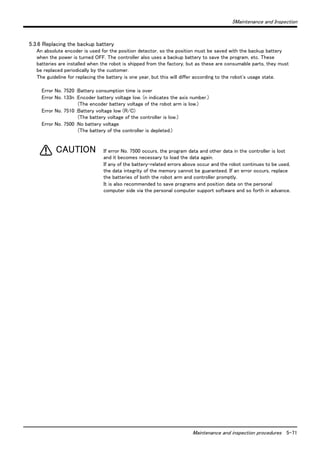
(1) Replacing the robot arm battery
Don't disconnect connector, etc. While replacing the battery, the encoder position
data is saved by the power supplied from the controller. Thus, if the cable
connection is incomplete, the encoder position data will be lost when the controller
power is turned OFF. Several batteries are used in the robot arm, but replace all old
batteries with new batteries at the same time.
CAUTION
Fig.5-15 : Replacing the battery
<2> Socket bolt (7 pcs.)
1) Confirm that the robot arm and controller are connected with a cable.
2) Turn the controller control power ON.
The position data is retained by the power supplied from the controller while replacing the battery. Thus, if
the cable is not connected correctly, or if the controller power is OFF, the position data will be lost.
3) Press the emergency stop button to set the robot in the emergency stop state. This is a measure for safety,
and must always be carried out.
4) Remove the seven socket bolt <2>, and remove the shoulder cover A. (Refer to "5.3.2Installing/removing
the cover" on page 58.)
5) The battery holder is located in the shoulder. Remove the old battery from the holder, and disconnect the
lead connector.
6) Insert the new battery into the holder, and connect the lead connector. Replace all batteries with new ones
at the same time.
7) All the batteries should check that it has been exchanged newly. If the old battery is contained, generating
heat and damaging may occur.
8) Install the shoulder cover A.
9) Initialize the battery consumption time.
Always carry out this step after replacing the battery, and initialize the battery usage time. Refer to the
separate "Instruction Manual/Detailed Explanation of Functions and Operations" for details on the opera-tion
methods.
[Caution] If the old battery is replaced because it has been used up, it is necessary to set the origin again.
Refer to "5.6Resetting the origin" on page 76 and reset the origin using the jig method or mechanical
stopper method or ABS origin method.
5-72 Maintenance and inspection procedures
Shoulder cover A
Battery
Shoulder
Lead connector](https://image.slidesharecdn.com/bfp-a8653j-141003204745-conversion-gate01/85/Mitsubshi-80-320.jpg)


![5 Maintenance and Inspection
5.6 Resetting the origin
The origin is set so that the robot can be used with a high accuracy. After purchasing the robot, always carry out
this step before starting work. The origin must be reset if the combination of robot and controller being used is
changed or if the motor is changed causing an encoder area. The types of origin setting methods are shown in
Table 5-10.
[Caution] If the old battery is replaced because it has been used up, it is necessary to set the origin again.Reset
the origin using the jig method or mechanical stopper method or ABS origin method.
.
Table 5-10 : Origin setting method
No Method Explanation Remarks
1 Origin data input
method
5-76 Resetting the origin
The origin data set as the default is input from
the T/B.
The setting method is explained in "2.4Setting the
origin" on page 19 .
2 Mechanical stopper
method
This origin posture is set by contacting each axis
against the mechanical stopper.
The setting method is explained in "5.6.1Mechanical
stopper method" on page 77 .
3 Jig method The origin posture is set with the calibration jig
installed.
The setting method is explained in "5.6.2Jig method" on
page 93 .
4 ABS origin method This method is used when the encoder backup
data lost in the cause such as battery cutting.
Before using this method, the origin must be set with the
other method with same encoder. The setting method is
explained in "5.6.3ABS origin method" on page 106.
5 User origin method A randomly designated position is set as the
origin posture.
The setting method is explained in "5.6.4User origin
method" on page 108.](https://image.slidesharecdn.com/bfp-a8653j-141003204745-conversion-gate01/85/Mitsubshi-84-320.jpg)
![5 Maintenance and Inspection
Resetting the origin 5-77
5.6.1 Mechanical stopper method
The method for setting the origin with the transportation jig is explained below.
This operation is carried out with the T/B. Set the [MODE] switch on the front of the controller to "MANUAL",
and set the T/B [ENABLE] switch to "ENABLE" to validate the T/B.
Here, if an axis is equipped with a brake, release the brake and move the arm with
both hands.At this point release the brakes and move the arm with both hands.
To ensure safety, the brake-release procedure described below should always be
done by two persons.
(1) J1 axis origin setting(mechanical stopper)
1) Press the [4] key on the menu screen, and dis-play
the Origin/BRK selection screen.
2) Press the [2] key , and display the Break release
selection screen.
3) Release the brake of the J1 axis.
Input "1" into the J1 axis. Set "0" to other
axes.
4) Confirm the axis for which the brakes are to be
released.
5) Pressing the [F1] key is kept with the enabling
switch of T/B pressed down. The brake is
released while pressing the key.
6) With both hands, slowly move the J1 axis in +
(plus) direction , and contact the axis against
the mechanical stopper.
CAUTION
~
SPACE
<MENU>
1.FILE/EDIT 2.RUN
3.PARAM. 4.ORIGIN/BRK
5.SET/INIT. 6.ENHANCED
123 CLOSE
<ORIGIN/BRAKE>
1.ORIGIN 2.BRAKE
<BRAKE>
123 CLOSE
J1:( 0 )J2:( 0 )J3:( 0 )
J4:( 0 )J5:( 0 )J6:( 0 )
J7:( 0 )J8:( 0 )
REL. 123 CLOSE
<BRAKE>
1
J1:( 0 )J2:( 0 )J3:( 0 )
J4:( 0 )J5:( 0 )J6:( 0 )
J7:( 0 )J8:( 0 )
REL. 123 CLOSE
J1(+)
Base front](https://image.slidesharecdn.com/bfp-a8653j-141003204745-conversion-gate01/85/Mitsubshi-85-320.jpg)
![5 Maintenance and Inspection
1
5-78 Resetting the origin
7) Detach the [F1] key and work the brake.
Press the [F4] key and return to the origin /
brake screen.
8) Press the [1] key , and display the Origin setting
selection screen.
9) Press the [2] key , and display the Mechanical
stopper selection screen.
10) Input "1" into the J1 axis. Set "0" to other
axes.
11) Press the [EXE] key , and display Confirmation
screen.
12) Press the [F1] key , and the origin position is
set up.
13) Setting of the origin is completed.
14) Refer to "5.6.5Recording the origin data" on
page 110 in this manual, and record the origin
data on the origin data seal.
<BRAKE>
J1:( 0 )J2:( 0 )J3:( 0 )
J4:( 0 )J5:( 0 )J6:( 0 )
J7:( 0 )J8:( 0 )
REL. 123 CLOSE
~
SPACE
<ORIGIN/BRAKE>
1.ORIGIN 2.BRAKE
123 CLOSE
<ORIGIN>
1.DATA 2.MECH
3.TOOL 4.ABS
5.USER
123 CLOSE
<ORIGIN> MECH
J1( 1 ) J2( ) J3( )
J4( ) J5( ) J6( )
J7( ) J8( )
123 CLOSE
<ORIGIN> MECH COMPLETED
J1( 1 ) J2( ) J3( )
J4( ) J5( ) J6( )
J7( ) J8( )
123 CLOSE
<ORIGIN> MECH
CHANGE TO ORIGIN. OK?
Yes 123 No
◇◆◇ Release the brake ◇◆◇
Do cursor movement into the parenthesis of each axis by the arrow key. The brakes can be released only for
the axis for which a "1" is displayed on the screen. If the brakes are not to be released, press the [0] key and
display a "0". If the [F1] key on the teaching pendant or the enabling switch is detached while the brakes are
released, the brakes will be work immediately.
◇◆◇ Select the axis of origin setting ◇◆◇
Do cursor movement into the parenthesis of each axis by the arrow key. The origin is set only for the axis for
which a "1" is displayed on the screen. If the origin is not to be set, press the [0] key and display a "0".](https://image.slidesharecdn.com/bfp-a8653j-141003204745-conversion-gate01/85/Mitsubshi-86-320.jpg)
![5 Maintenance and Inspection
Resetting the origin 5-79
(2) J2 axis origin setting(mechanical stopper)
1) Press the [4] key on the menu screen, and dis-play
the Origin/BRK selection screen.
2) Press the [2] key , and display the Break release
selection screen.
3) Release the brake of the J2 axis.
Input "1" into the J2 axis. Set "0" to other
axes.
4) Confirm the axis for which the brakes are to be
released.
5) Pressing the [F1] key is kept with the enabling
switch of T/B pressed down. The brake is
released while pressing the key.
6) With both hands, slowly move the J2 axis in +
(plus) direction , and contact the axis against
the mechanical stopper.
7) Detach the [F1] key and work the brake.
Press the [F4] key and return to the Origin /
BRK screen.
~
SPACE
<MENU>
1.FILE/EDIT 2.RUN
3.PARAM. 4.ORIGIN/BRK
5.SET/INIT. 6.ENHANCED
123 CLOSE
<ORIGIN/BRAKE>
1.ORIGIN 2.BRAKE
123 CLOSE
<BRAKE>
J1:( 0 )J2:( 0 )J3:( 0 )
J4:( 0 )J5:( 0 )J6:( 0 )
J7:( 0 )J8:( 0 )
REL. 123 CLOSE
<BRAKE>
1
J1:( 0 )J2:( 0 )J3:( 0 )
J4:( 0 )J5:( 0 )J6:( 0 )
J7:( 0 )J8:( 0 )
REL. 123 CLOSE
J2(-) J2(-)
Front of base Front of base
5-axis type 6-axis type
<BRAKE>
1
J1:( 0 )J2:( 0 )J3:( 0 )
J4:( 0 )J5:( 0 )J6:( 0 )
J7:( 0 )J8:( 0 )
REL. 123 CLOSE](https://image.slidesharecdn.com/bfp-a8653j-141003204745-conversion-gate01/85/Mitsubshi-87-320.jpg)
![5 Maintenance and Inspection
5-80 Resetting the origin
8) Press the [1] key , and display the Origin setting
selection screen.
9) Press the [2] key , and display the Mechanical
stopper selection screen.
10) Input "1" into the J2 axis. Set "0" to other
axes.
11) Press the [EXE] key , and display Confirmation
screen.
12) Press the [F1] key , and the origin position is
set up.
13) Setting of the origin is completed.
14) Refer to "5.6.5Recording the origin data" on
page 110 in this manual, and record the origin
data on the origin data seal.
~
SPACE
<ORIGIN/BRAKE>
1.ORIGIN 2.BRAKE
123 CLOSE
<ORIGIN>
1.DATA 2.MECH
3.TOOL 4.ABS
5.USER
123 CLOSE
<ORIGIN> MECH
J1( ) J2( 1 ) J3( )
J4( ) J5( ) J6( )
J7( ) J8( )
123 CLOSE
<ORIGIN> MECH
CHANGE TO ORIGIN. OK?
Yes 123 No
<ORIGIN> MECH COMPLETED
J1( ) J2( 1 ) J3( )
J4( ) J5( ) J6( )
J7( ) J8( )
123 CLOSE
◇◆◇ Release the brake ◇◆◇
Do cursor movement into the parenthesis of each axis by the arrow key. The brakes can be released only for
the axis for which a "1" is displayed on the screen. If the brakes are not to be released, press the [0] key and
display a "0". If the [F1] key on the teaching pendant or the enabling switch is detached while the brakes are
released, the brakes will be work immediately.
◇◆◇ Select the axis of origin setting ◇◆◇
Do cursor movement into the parenthesis of each axis by the arrow key. The origin is set only for the axis for
which a "1" is displayed on the screen. If the origin is not to be set, press the [0] key and display a "0".](https://image.slidesharecdn.com/bfp-a8653j-141003204745-conversion-gate01/85/Mitsubshi-88-320.jpg)
![5 Maintenance and Inspection
Resetting the origin 5-81
(3) J3 axis origin setting(mechanical stopper)
1) Press the [4] key on the menu screen, and dis-play
the Origin/BRK selection screen.
2) Press the [2] key , and display the Break release
selection screen.
3) Release the brake of the J3 axis.
Input "1" into the J3 axis. Set "0" to other
axes.
4) Confirm the axis for which the brakes are to be
released.
5) Pressing the [F1] key is kept with the enabling
switch of T/B pressed down. The brake is
released while pressing the key.
6) With both hands, slowly move the J3 axis in +
(plus) direction , and contact the axis against
the mechanical stopper.
7) Detach the [F1] key and work the brake.
Press the [F4] key and return to the Origin /
BRK screen.
~
SPACE
<MENU>
1.FILE/EDIT 2.RUN
3.PARAM. 4.ORIGIN/BRK
5.SET/INIT. 6.ENHANCED
123 CLOSE
<ORIGIN/BRAKE>
1.ORIGIN 2.BRAKE
123 CLOSE
<BRAKE>
0
J1:( 0 )J2:( 0 )J3:( 1 )
J4:( 0 )J5:( 0 )J6:( 0 )
J7:( 0 )J8:( 0 )
REL. 123 CLOSE
<BRAKE>
J1:( 0 )J2:( 0 )J3:( 1 )
J4:( 0 )J5:( 0 )J6:( 0 )
J7:( 0 )J8:( 0 )
REL. 123 CLOSE
J3(+) J3(+)
Front of base Front of base
5-axis type 6-axis type
<BRAKE>
J1:( 0 )J2:( 0 )J3:( 1 )
J4:( 0 )J5:( 0 )J6:( 0 )
J7:( 0 )J8:( 0 )
REL. 123 CLOSE](https://image.slidesharecdn.com/bfp-a8653j-141003204745-conversion-gate01/85/Mitsubshi-89-320.jpg)
![5 Maintenance and Inspection
5-82 Resetting the origin
8) Press the [1] key , and display the Origin setting
selection screen.
9) Press the [2] key , and display the Mechanical
stopper selection screen.
10) Input "1" into the J3 axis. Set "0" to other
axes.
11) Press the [EXE] key , and display Confirmation
screen.
12) Press the [F1] key , and the origin position is
set up.
13) Setting of the origin is completed.
14) Refer to "5.6.5Recording the origin data" on
page 110 in this manual, and record the origin
data on the origin data seal.
~
SPACE
<ORIGIN/BRAKE>
1.ORIGIN 2.BRAKE
123 CLOSE
<ORIGIN>
1.DATA 2.MECH
3.TOOL 4.ABS
5.USER
123 CLOSE
<ORIGIN> MECH
J1( ) J2( ) J3( 1 )
J4( ) J5( ) J6( )
J7( ) J8( )
123 CLOSE
<ORIGIN> MECH
CHANGE TO ORIGIN. OK?
Yes 123 No
<ORIGIN> MECH COMPLETED
J1( ) J2( ) J3( 1 )
J4( ) J5( ) J6( )
J7( ) J8( )
123 CLOSE
◇◆◇ Release the brake ◇◆◇
Do cursor movement into the parenthesis of each axis by the arrow key. The brakes can be released only for
the axis for which a "1" is displayed on the screen. If the brakes are not to be released, press the [0] key and
display a "0". If the [F1] key on the teaching pendant or the enabling switch is detached while the brakes are
released, the brakes will be work immediately.
◇◆◇ Select the axis of origin setting ◇◆◇
Do cursor movement into the parenthesis of each axis by the arrow key. The origin is set only for the axis for
which a "1" is displayed on the screen. If the origin is not to be set, press the [0] key and display a "0".](https://image.slidesharecdn.com/bfp-a8653j-141003204745-conversion-gate01/85/Mitsubshi-90-320.jpg)
![5 Maintenance and Inspection
Resetting the origin 5-83
(4) J4 axis origin setting(6-axis type only)(mechanical stopper)
"5.6.5Recording the origin data" on page 110
1) Press the [4] key on the menu screen, and dis-play
the Origin/BRK selection screen.
2) Press the [2] key , and display the Brake release
selection screen.
3) Before moving the J4 axis, move the J3 axis to
prevent arm interference.
Input "1" into the J3 axis. Set "0" to other axes.
4) Confirm the axis for which the brakes are to be
released.
5) Pressing the [F1] key is kept with the enabling
switch of T/B pressed down. The brake is
released while pressing the key.
6) With both hands, slowly move the J3 axis in -
(minus) direction. Stop at a position where the
arm will not interfere even if the J4 axis is
rotated, and then apply the brakes.
Then, set the J4 axis origin.
7) Detach the [F1] key and work the brake.
~
SPACE
1.FILE/EDIT 2.RUN
3.PARAM. 4.ORIGIN/BRK
5.SET/INIT. 6.ENHANCED
123 CLOSE
<ORIGIN/BRAKE>
1.ORIGIN 2.BRAKE
123 CLOSE
J3(-)
<MENU>
Front of base
<BRAKE>
J1:( 0 )J2:( 0 )J3:( 1 )
J4:( 0 )J5:( 0 )J6:( 0 )
J7:( 0 )J8:( 0 )
REL. 123 CLOSE
<BRAKE>
J1:( 0 )J2:( 0 )J3:( 1 )
J4:( 0 )J5:( 0 )J6:( 0 )
J7:( 0 )J8:( 0 )
REL. 123 CLOSE](https://image.slidesharecdn.com/bfp-a8653j-141003204745-conversion-gate01/85/Mitsubshi-91-320.jpg)
![5 Maintenance and Inspection
5-84 Resetting the origin
8) The type which does not have the brake in the
J4 axis skips to "1." .
The type with the brake release the brake. Input
"1" into the J4 axis. Set "0" to other axes.
9) Confirm the axis for which the brakes are to be
released.
10) Pressing the [F1] key is kept with the enabling
switch of T/B pressed down. The brake is
released while pressing the key.
11) With both hands, slowly move the J4 axis in +
(plus) direction , and contact the axis against
the mechanical stopper.
12) Detach the [F1] key and work the brake.
Press the [F4] key and return to the Origin /
BRK screen.
13) Press the [2] key , and display the Mechanical
stopper selection screen.
14) Input "1" into the J4 axis. Set "0" to other
axes.
15) Press the [EXE] key , and display Confirmation
screen.
~
SPACE
J4(+)
Front of base
~
SPACE
<BRAKE>
J1:( 0 )J2:( 0 )J3:( 0 )
J4:( 0 )J5:( 0 )J6:( 0 )
J7:( 0 )J8:( 0 )
REL. 123 CLOSE
<BRAKE>
J1:( 0 )J2:( 0 )J3:( 0 )
J4:( 0 )J5:( 0 )J6:( 0 )
J7:( 0 )J8:( 0 )
REL. 123 CLOSE
<BRAKE>
J1:( 0 )J2:( 0 )J3:( 0 )
J4:( 0 )J5:( 0 )J6:( 0 )
J7:( 0 )J8:( 0 )
REL. 123 CLOSE
<ORIGIN>
1.DATA 2.MECH
3.TOOL 4.ABS
5.USER
123 CLOSE
<ORIGIN> MECH
J1( ) J2( ) J3( )
J4( 1 ) J5( ) J6( )
J7( ) J8( )
123 CLOSE](https://image.slidesharecdn.com/bfp-a8653j-141003204745-conversion-gate01/85/Mitsubshi-92-320.jpg)
![5 Maintenance and Inspection
16) Press the [F1] key , and the origin position is
Resetting the origin 5-85
set up.
17) Setting of the origin is completed.
18) Refer to "5.6.3ABS origin method" on page 106
in this manual, and record the origin data on the
origin data seal.
<ORIGIN> MECH
CHANGE TO ORIGIN. OK?
Yes 123 No
<ORIGIN> MECH COMPLETED
J1( ) J2( ) J3( )
J4( 1 ) J5( ) J6( )
J7( ) J8( )
123 CLOSE
◇◆◇ Release the brake ◇◆◇
Do cursor movement into the parenthesis of each axis by the arrow key. The brakes can be released only for
the axis for which a "1" is displayed on the screen. If the brakes are not to be released, press the [0] key and
display a "0". If the [F1] key on the teaching pendant or the enabling switch is detached while the brakes are
released, the brakes will be work immediately.
◇◆◇ Select the axis of origin setting ◇◆◇
Do cursor movement into the parenthesis of each axis by the arrow key. The origin is set only for the axis for
which a "1" is displayed on the screen. If the origin is not to be set, press the [0] key and display a "0".](https://image.slidesharecdn.com/bfp-a8653j-141003204745-conversion-gate01/85/Mitsubshi-93-320.jpg)
![5 Maintenance and Inspection
(5) J5 axis origin setting(mechanical stopper)
5-86 Resetting the origin
1) Press the [4] key on the menu screen, and dis-play
the Origin/BRK selection screen.
2) Press the [2] key , and display the Break
release selection screen.
3) Release the brake of the J5 axis.
Input "1" into the J5 axis. Set "0" to other axes
4) Confirm the axis for which the brakes are to be
released.
5) Pressing the [F1] key is kept with the enabling
switch of T/B pressed down. The brake is
released while pressing the key.
6) With both hands, slowly move the J5 axis in +
(plus) direction , and contact the axis against
the mechanical stopper.
7) Detach the [F1] key and work the brake.
Press the [F4] key and return to the Origin /
BRK screen.
~
SPACE
J5(+)
5-axis type 6-axis type
J5(+)
J4(+)
Front of base Front of base
* The 6 axis type direction of J5 axis
shows the case where the J4 axis is
in the mechanical stopper position.
<MENU>
1.FILE/EDIT 2.RUN
3.PARAM. 4.ORIGIN/BRK
5.SET/INIT. 6.ENHANCED
123 CLOSE
<ORIGIN/BRAKE>
1.ORIGIN 2.BRAKE
123 CLOSE
<BRAKE>
J1:( 0 )J2:( 0 )J3:( 0 )
J4:( 0 )J5:( 0 )J6:( 0 )
J7:( 0 )J8:( 0 )
REL. 123 CLOSE
<BRAKE>
J1:( 0 )J2:( 0 )J3:( 0 )
J4:( 0 )J5:( 0 )J6:( 0 )
J7:( 0 )J8:( 0 )
REL. 123 CLOSE
<BRAKE>
J1:( 0 )J2:( 0 )J3:( 0 )
J4:( 0 )J5:( 0 )J6:( 0 )
J7:( 0 )J8:( 0 )
REL. 123 CLOSE](https://image.slidesharecdn.com/bfp-a8653j-141003204745-conversion-gate01/85/Mitsubshi-94-320.jpg)
![5 Maintenance and Inspection
8) Press the [1] key , and display the Origin setting
Resetting the origin 5-87
selection screen.
9) Press the [2] key , and display the Mechanical
stopper selection screen.
10) Input "1" into the J5 axis. Set "0" to other
axes.
11) Press the [EXE] key , and display Confirmation
screen.
12) Press the [F1] key , and the origin position is
set up.
13) Setting of the origin is completed.
14) Refer to "5.6.3ABS origin method" on page 106
in this manual, and record the origin data on the
origin data seal.
~
SPACE
<ORIGIN/BRAKE>
1.ORIGIN 2.BRAKE
123 CLOSE
<ORIGIN>
1.DATA 2.MECH
3.TOOL 4.ABS
5.USER
123 CLOSE
<ORIGIN> MECH
J1( ) J2( ) J3( )
J4( ) J5( 1 ) J6( )
J7( ) J8( )
123 CLOSE
<ORIGIN> MECH
CHANGE TO ORIGIN. OK?
Yes 123 No
<ORIGIN> MECH COMPLETED
J1( ) J2( ) J3( )
J4( ) J5( 1 ) J6( )
J7( ) J8( )
123 CLOSE
◇◆◇ Release the brake ◇◆◇
Do cursor movement into the parenthesis of each axis by the arrow key. The brakes can be released only for
the axis for which a "1" is displayed on the screen. If the brakes are not to be released, press the [0] key and
display a "0". If the [F1] key on the teaching pendant or the enabling switch is detached while the brakes are
released, the brakes will be work immediately.
◇◆◇ Select the axis of origin setting ◇◆◇
Do cursor movement into the parenthesis of each axis by the arrow key. The origin is set only for the axis for
which a "1" is displayed on the screen. If the origin is not to be set, press the [0] key and display a "0".](https://image.slidesharecdn.com/bfp-a8653j-141003204745-conversion-gate01/85/Mitsubshi-95-320.jpg)
![5 Maintenance and Inspection
(6) J6 axis origin setting(mechanical stopper
<MENU>
1.FILE/EDIT 2.RUN
3.PARAM. 4.ORIGIN/BRK
5.SET/INIT. 6.ENHANCED
123 CLOSE
<ORIGIN/BRAKE>
1.ORIGIN 2.BRAKE
123 CLOSE
Bolt (M5: 2 bolts)
5-88 Resetting the origin
1) Install the bolts (two M5 bolts prepared by
customer) at opposing positions on the
mechanical interface.
2) Press the [4] key on the menu screen, and dis-play
the Origin/BRK selection screen.
3) Press the [2] key , and display the Break
release selection screen.
4) The type which does not have the brake in the
J6 axis skips to "7." .
The type with the brake release the brake.
Input "1" into the J6 axis. Set "0" to other
axes.
5) Confirm the axis for which the brakes are to be
released.
6) Pressing the [F1] key is kept with the enabling
switch of T/B pressed down. The brake is
released while pressing the key.
7) Hold the bolts mounted in step "1)" above with
hands, rotate them slowly and align the ABS
mark of the J6 axis with the ABS mark of the
wrist area.
8) Detach the [F1] key and work the brake.
Press the [F4] key and return to the Origin /
BRK screen.
~
SPACE
The J6-axis dose not have a
mechanical stopper.
When setting the origin position ,
do not rotate the axis more than
themotion range( ± 200 deg.).
CAUTION
J6 axis
ABS mark
Prepared by customer
<ORIGIN/BRAKE>
1.ORIGIN 2.BRAKE
123 CLOSE
<BRAKE>
J1:( 0 )J2:( 0 )J3:( 0 )
J4:( 0 )J5:( 0 )J6:( 0 )
J7:( 0 )J8:( 0 )
REL. 123 CLOSE
<BRAKE>
J1:( 0 )J2:( 0 )J3:( 0 )
J4:( 0 )J5:( 0 )J6:( 0 )
J7:( 0 )J8:( 0 )
REL. 123 CLOSE
<BRAKE>
J1:( 0 )J2:( 0 )J3:( 0 )
J4:( 0 )J5:( 0 )J6:( 0 )
J7:( 0 )J8:( 0 )
REL. 123 CLOSE](https://image.slidesharecdn.com/bfp-a8653j-141003204745-conversion-gate01/85/Mitsubshi-96-320.jpg)
![5 Maintenance and Inspection
9) Press the [1] key , and display the Origin setting
Resetting the origin 5-89
selection screen.
10) Press the [2] key , and display the Mechanical
stopper selection screen.
11) Input "1" into the J6 axis. Set "0" to other
axes.
12) Press the [EXE] key , and display Confirmation
screen.
13) Press the [F1] key , and the origin position is
set up.
14) Setting of the origin is completed.
15) Refer to "5.6.3ABS origin method" on page 106
in this manual, and record the origin data on the
origin data seal.
~
SPACE
<ORIGIN/BRAKE>
1.ORIGIN 2.BRAKE
123 CLOSE
<ORIGIN>
1.DATA 2.MECH
3.TOOL 4.ABS
5.USER
123 CLOSE
<ORIGIN> MECH
J1( ) J2( ) J3( )
J4( ) J5( ) J6( 1 )
J7( ) J8( )
123 CLOSE
<ORIGIN> MECH
CHANGE TO ORIGIN. OK?
Yes 123 No
<ORIGIN> MECH COMPLETED
J1( ) J2( ) J3( )
J4( ) J5( ) J6( 1 )
J7( ) J8( )
123 CLOSE
◇◆◇ Release the brake ◇◆◇
Do cursor movement into the parenthesis of each axis by the arrow key. The brakes can be released only for
the axis for which a "1" is displayed on the screen. If the brakes are not to be released, press the [0] key and
display a "0". If the [F1] key on the teaching pendant or the enabling switch is detached while the brakes are
released, the brakes will be work immediately.
◇◆◇ Select the axis of origin setting ◇◆◇
Do cursor movement into the parenthesis of each axis by the arrow key. The origin is set only for the axis for
which a "1" is displayed on the screen. If the origin is not to be set, press the [0] key and display a "0".](https://image.slidesharecdn.com/bfp-a8653j-141003204745-conversion-gate01/85/Mitsubshi-97-320.jpg)
![5 Maintenance and Inspection
(7) All axis origin setting
■ In the case of the 5-axis type
1) Refer to the paragraphs from "(1)J1 axis origin setting(mechanical stopper)" on page 77 to "(6)J6 axis origin
setting(mechanical stopper" on page 88 above for the description of how to adjust the origins of the J1 to J6
axes. Line up the ABS marks for the J6 axis and move the other axes into contact with the mechanical
stoppers. At this point, the robot will have the posture shown below
<ORIGIN>
1.DATA 2.MECH
3.TOOL 4.ABS
5.USER
123 CLOSE
5-90 Resetting the origin
J1(+)
2) Press the [1] key , and display the Origin set-ting
selection screen.
3) Press the [2] key , and display the Mechanical
stopper selection screen.
4) Input "1" into the J1 to J6 axis. Set "0" to
other axes.
5) Press the [EXE] key , and display Confirmation
screen.
6) Press the [F1] key , and the origin position is
set up.
7) Setting of the origin is completed.
8) Refer to "5.6.3ABS origin method" on page
106 in this manual, and record the origin data on
the origin data seal.
J2(-)
J3(+)
J5(+)
J6 (ABS mark is in agreement )
SPACE
<ORIGIN/BRAKE>
1.ORIGIN 2.BRAKE
123 CLOSE
<ORIGIN> MECH
J1( 1 ) J2( 1 ) J3( 1 )
J4( ) J5( 1 ) J6( 1 )
J7( ) J8( )
123 CLOSE
<ORIGIN> MECH
CHANGE TO ORIGIN. OK?
Yes 123 No
<ORIGIN> MECH COMPLETED
J1( 1 ) J2( 1 ) J3( 1 )
J4( ) J5( 1 ) J6( 1 )
J7( ) J8( )
123 CLOSE](https://image.slidesharecdn.com/bfp-a8653j-141003204745-conversion-gate01/85/Mitsubshi-98-320.jpg)
![5 Maintenance and Inspection
Resetting the origin 5-91
■ In the case of the 6-axis type
1) First, adjust the origin positions of the J4, J5 and J6 axes by referring to the paragraphs "(4)J4 axis origin
setting(6-axis type only)(mechanical stopper)" on page 83, "(5)J5 axis origin setting(mechanical stopper)" on
page 86 and "(6)J6 axis origin setting(mechanical stopper" on page 88 above. Line up the ABS marks for the
J6 axis and move the other axes into contact with the mechanical stoppers. At this point, the robot will have
the posture shown below.
J6 (ABS mark is in agreement )
2) Press the [1] key , and display the Origin set-ting
selection screen.
3) Press the [2] key , and display the Mechanical
stopper selection screen.
4) Input "1" into the J4 to J6 axis. Set "0" to
other axes.
5) Press the [EXE] key , and display Confirmation
screen..
6) Press the [F1] key , and the origin position is
set up.
7) Setting of the origin of J4, J5 and J6 axis is
completed.
8) Refer to "5.6.3ABS origin method" on page
106 in this manual, and record the origin data on
the origin data seal.
9) Next, set the origins for the J1, J2 and J3 axes.
J4(+)
J5(+)
SPACE
<ORIGIN/BRAKE>
1.ORIGIN 2.BRAKE
123 CLOSE
<ORIGIN>
1.DATA 2.MECH
3.TOOL 4.ABS
5.USER
123 CLOSE
<ORIGIN> MECH
J1( ) J2( ) J3( )
J4( 1 ) J5( 1 ) J6( 1 )
J7( ) J8( )
123 CLOSE
<ORIGIN> MECH
CHANGE TO ORIGIN. OK?
Yes 123 No
<ORIGIN> MECH COMPLETED
J1( ) J2( ) J3( )
J4( 1 ) J5( 1 ) J6( 1 )
J7( ) J8( )
123 CLOSE](https://image.slidesharecdn.com/bfp-a8653j-141003204745-conversion-gate01/85/Mitsubshi-99-320.jpg)
![5 Maintenance and Inspection
10) In order to avoid interference with the robot arm, return the J4 and J5 axes to the ABS mark positions. See
"Fig. 5-18ABS mark attachment positions" on page 106 for the ABS mark positions.
11) Move the J1, J2 and J3 axes into contact with the mechanical stoppers by referring to "(1)J1 axis origin
setting(mechanical stopper)" on page 77, "(2)J2 axis origin setting(mechanical stopper)" on page 79 and
"(3)J3 axis origin setting(mechanical stopper)" on page 81.
At this point, the robot will have the posture shown below
5-92 Resetting the origin
J1(+)
12) Press the [1] key , and display the Origin set-ting
selection screen.
13) Press the [2] key , and display the Mechanical
stopper selection screen.
14) Input "1" into the J1 to J3 axis. Set "0" to
other axes.
15) Press the [EXE] key , and display Confirma-tion
screen.
16) Press the [F1] key , and the origin position is
set up.
17) Setting of the origin of J1, J2 and J3 axis is
completed.
18) Refer to "5.6.3ABS origin method" on page
106 in this manual, and record the origin data on
the origin data seal.
J2(-)
J3(+)
SPACE
<ORIGIN/BRAKE>
1.ORIGIN 2.BRAKE
123 CLOSE
<ORIGIN>
1.DATA 2.MECH
3.TOOL 4.ABS
5.USER
123 CLOSE
<ORIGIN> MECH
J1( 1 ) J2( 1 ) J3( 1 )
J4( ) J5( ) J6( )
J7( ) J8( )
123 CLOSE
<ORIGIN> MECH
CHANGE TO ORIGIN. OK?
Yes 123 No
<ORIGIN> MECH COMPLETED
J1( 1 ) J2( 1 ) J3( 1 )
J4( ) J5( ) J6( )
J7( ) J8( )
123 CLOSE](https://image.slidesharecdn.com/bfp-a8653j-141003204745-conversion-gate01/85/Mitsubshi-100-320.jpg)
![5 Maintenance and Inspection
Resetting the origin 5-93
5.6.2 Jig method
This method is using the origin setting tool. If the origin setting tool is required, please ask nearby dealer. The
reference figure of the origin setting tool is shown in Fig. 5-17.
300
Fig.5-17 : Reference dimension of origin setting tool
C0.5
RZ6.3
The procedure of setting the origin with the origin setting tool is shown below.
φ6-0.01
-0.02
Carry out this method for each axis.
First, set each axis by the origin position. There are the method of releasing the brake and adjusting with the origin
position manually and the method of adjusting with the origin position by jog feed. Here, explain operation by brake
release.
Then, do origin setting operation and set up the origin.
To ensure safety, the brake-release procedure described below should always be
done by two persons.
CAUTION
This operation is carried out with the teaching pendant. Set the [MODE] switch on the front of the controller to
"MANUAL", and set the [ENABLE] switch on the teaching pendant to "ENABLE" to enable the teaching pendant.
Do the following operations, pressing down the enabling switch of T/B lightly.](https://image.slidesharecdn.com/bfp-a8653j-141003204745-conversion-gate01/85/Mitsubshi-101-320.jpg)
![5 Maintenance and Inspection
(1) J1 axis origin setting
<ORIGIN/BRAKE>
1.ORIGIN 2.BRAKE
<BRAKE>
<BRAKE>
J1:( 0 )J2:( 0 )J3:( 0 )
J4:( 0 )J5:( 0 )J6:( 0 )
J7:( 0 )J8:( 0 )
J1:( 1 )J2:( 0 )J3:( 0 )
J4:( 0 )J5:( 0 )J6:( 0 )
J7:( 0 )J8:( 0 )
REL. 123 CLOSE
REL. 123 CLOSE
<BRAKE>
J1:( 1 )J2:( 0 )J3:( 0 )
J4:( 0 )J5:( 0 )J6:( 0 )
J7:( 0 )J8:( 0 )
REL. 123 CLOSE
5-94 Resetting the origin
1) Press the [4] key on the menu screen, and dis-play
the Origin/Break selection screen.
2) Press the [2] key , and display the Break
release selection screen.
3) Release the brake of the J1 axis.
Input "1" into the J1 axis. Set "0" to other
axes.
4) Confirm the axis for which the brakes are to be
released.
5) Pressing the [F1] key is kept with the enabling
switch of T/B pressed down. The brake is
released while pressing the key.
6) Move the J1 axis slowly toward the front using
both hands. Align the pinhole of the No.1 arm
and the pinhole at the base section, feed
through the origin jig (φ6) into the pinholes and
fasten.
7) Detach the [F1] key and work the brake.
Press the [F4] key and return to the origin /
brake screen.
8) Press the [1] key , and display the Origin setting
selection screen.
<MENU>
1.FILE/EDIT 2.RUN
3.PARAM. 4.ORIGIN/BRK
5.SET/INIT. 6.ENHANCED
123 CLOSE
Select ORIGIN/BRK
Select BREAK
123 CLOSE
<BRAKE>
J1:( 0 )J2:( 0 )J3:( 0 )
J4:( 0 )J5:( 0 )J6:( 0 )
J7:( 0 )J8:( 0 )
REL. 123 CLOSE
select axis
~
SPACE
Breake release
Pinhole (J1 axis)
Diagram of the robot viewed from the top
Complete breake release
<ORIGIN/BRAKE>
1.ORIGIN 2.BRAKE
123 CLOSE](https://image.slidesharecdn.com/bfp-a8653j-141003204745-conversion-gate01/85/Mitsubshi-102-320.jpg)
![5 Maintenance and Inspection
9) Press the [3] key , and display the Tool selection
Resetting the origin 5-95
screen.
10) Input "1" into the J1 axis. Set "0" to other
axes.
11) Press the [EXE] key , and display Confirmation
screen.
12) Press the [F1] key , and the origin position is
set up.
13) Setting of the origin is completed.
14) Refer to "5.6.5Recording the origin data" on
page 110 in this manual, and record the origin
data on the origin data seal.
<ORIGIN>
1.DATA 2.MECH
3.TOOL 4.ABS
5.USER
123 CLOSE
Select TOOL
<TOOL>
J1:( 1 )J2:( 0 )J3:( 0 )
J4:( 0 )J5:( 0 )J6:( 0 )
J7:( 0 )J8:( 0 )
REL. 123 CLOSE
~
SPACE
<ORIGIN> TOOL
CHANGE TO ORIGIN. OK?
Yes 123 No
<TOOL>
COMPLETED
J1:( 1 )J2:( 0 )J3:( 0 )
J4:( 0 )J5:( 0 )J6:( 0 )
J7:( 0 )J8:( 0 )
REL. 123 CLOSE
◇◆◇ Release the brake ◇◆◇
Do cursor movement into the parenthesis of each axis by the arrow key. The brakes can be released only for
the axis for which a "1" is displayed on the screen. If the brakes are not to be released, press the [0] key and
display a "0". If the [F1] key on the teaching pendant or the enabling switch is detached while the brakes are
released, the brakes will be work immediately.
◇◆◇ Select the axis of origin setting ◇◆◇
Do cursor movement into the parenthesis of each axis by the arrow key. The origin is set only for the axis for
which a "1" is displayed on the screen. If the origin is not to be set, press the [0] key and display a "0".](https://image.slidesharecdn.com/bfp-a8653j-141003204745-conversion-gate01/85/Mitsubshi-103-320.jpg)
![5 Maintenance and Inspection
(2) J2 axis origin setting
0 1
5-96 Resetting the origin
1) Press the [4] key on the menu screen, and dis-play
the Origin/Break selection screen.
2) Press the [2] key , and display the Break
release selection screen.
3) Release the brake of the J2 axis.
Input "1" into the J2 axis. Set "0" to other
axes.
4) Confirm the axis for which the brakes are to be
released.
5) One worker must securely support the upper
arm with both hands.
6) Pressing the [F1] key is kept with the enabling
switch of T/B pressed down. The brake is
released while pressing the key.
7) Move the J2 axis slowly toward the front using
both hands. Align the pinhole of the No.1 arm
and the pinhole at the base section, feed
through the origin jig (φ6) into the pinholes and
fasten.
For safety purposes, the step for releasing the brakes must be carried out by two
workers. One worker must operate the T/B, and the other must support the arm.
When the brakes are released, the robot arm could drop by its own weight depending
on the posture.
If [F1] key or enable switch of T/B is released, the brakes will be work immediately.
<MENU>
1.FILE/EDIT 2.RUN
3.PARAM. 4.ORIGIN/BRK
5.SET/INIT. 6.ENHANCED
123 CLOSE
<ORIGIN/BRAKE>
1.ORIGIN 2.BRAKE
123 CLOSE
~
SPACE
<BRAKE>
J1:( 0 )J2:( 0 )J3:( 0 )
J4:( 0 )J5:( 0 )J6:( 0 )
J7:( 0 )J8:( 0 )
REL. 123 CLOSE
<BRAKE>
J1:( 0 )J2:( 0 )J3:( 0 )
J4:( 0 )J5:( 0 )J6:( 0 )
J7:( 0 )J8:( 0 )
REL. 123 CLOSE
Pinhole (J2 axis) Pinhole (J2 axis)
5-axis type 6-axis type
CAUTION
CAUTION](https://image.slidesharecdn.com/bfp-a8653j-141003204745-conversion-gate01/85/Mitsubshi-104-320.jpg)
![5 Maintenance and Inspection
8) Detach the [F1] key and work the brake.
Press the [F4] key and return to the origin /
brake screen.
9) Press the [1] key , and display the Origin setting
Resetting the origin 5-97
selection screen.
10) Press the [3] key , and display the Tool selec-tion
screen.
11) Input "1" into the J2 axis. Set "0" to other
axes.
12) Press the [EXE] key , and display Confirmation
screen.
13) Press the [F1] key , and the origin position is
set up.
14) Setting of the origin is completed.
15) Refer to "5.6.5Recording the origin data" on
page 110 in this manual, and record the origin
data on the origin data seal.
<BRAKE>
0
1
J1:( )J2:( 0 )J3:( 0 )
J4:( 0 )J5:( 0 )J6:( 0 )
J7:( 0 )J8:( 0 )
REL. 123 CLOSE
<ORIGIN/BRAKE>
1.ORIGIN 2.BRAKE
123 CLOSE
<ORIGIN>
1.DATA 2.MECH
3.TOOL 4.ABS
5.USER
123 CLOSE
~
SPACE
<TOOL>
0 1
J1:( 1 )J2:( 0 )J3:( 0 )
J4:( 0 )J5:( 0 )J6:( 0 )
J7:( 0 )J8:( 0 )
REL. 123 CLOSE
<ORIGIN> TOOL
CHANGE TO ORIGIN. OK?
Yes 123 No
<TOOL>
0
COMPLETED
1
J1:( 1 )J2:( 0 )J3:( 0 )
J4:( 0 )J5:( 0 )J6:( 0 )
J7:( 0 )J8:( 0 )
REL. 123 CLOSE
◇◆◇ Release the brake ◇◆◇
Do cursor movement into the parenthesis of each axis by the arrow key. The brakes can be released only for
the axis for which a "1" is displayed on the screen. If the brakes are not to be released, press the [0] key and
display a "0". If the [F1] key on the teaching pendant or the enabling switch is detached while the brakes are
released, the brakes will be work immediately.
◇◆◇ Select the axis of origin setting ◇◆◇
Do cursor movement into the parenthesis of each axis by the arrow key. The origin is set only for the axis for
which a "1" is displayed on the screen. If the origin is not to be set, press the [0] key and display a "0".](https://image.slidesharecdn.com/bfp-a8653j-141003204745-conversion-gate01/85/Mitsubshi-105-320.jpg)
![5 Maintenance and Inspection
(3) J3 axis origin setting
0 1
5-98 Resetting the origin
1) Press the [4] key on the menu screen, and dis-play
the Origin/Break selection screen.
2) Press the [2] key , and display the Break
release selection screen.
3) Release the brake of the J3 axis.
Input "1" into the J3 axis. Set "0" to other
axes.
4) Confirm the axis for which the brakes are to be
released.
5) One worker must securely support the upper
arm with both hands.
6) Pressing the [F1] key is kept with the enabling
switch of T/B pressed down. The brake is
released while pressing the key.
7) Move the J3 axis slowly toward the front using
both hands. Align the pinhole of the No.1 arm
and the pinhole at the base section, feed
through the origin jig (φ6) into the pinholes and
fasten.
For safety purposes, the step for releasing the brakes must be carried out by two
workers. One worker must operate the T/B, and the other must support the arm.
When the brakes are released, the robot arm could drop by its own weight depending
on the posture.
If [F1] key or enable switch of T/B is released, the brakes will be work immediately.
<MENU>
1.FILE/EDIT 2.RUN
3.PARAM. 4.ORIGIN/BRK
5.SET/INIT. 6.ENHANCED
123 CLOSE
<ORIGIN/BRAKE>
1.ORIGIN 2.BRAKE
123 CLOSE
~
SPACE
<BRAKE>
J1:( 0 )J2:( 0 )J3:( 0 )
J4:( 0 )J5:( 0 )J6:( 0 )
J7:( 0 )J8:( 0 )
REL. 123 CLOSE
<BRAKE>
J1:( )J2:( 0 )J3:( 0 )
J4:( 0 )J5:( 0 )J6:( 0 )
J7:( 0 )J8:( 0 )
REL. 123 CLOSE
Pinhole (J3 axis) Pinhole (J3 axis)
5-axis type 6-axis type
CAUTION
CAUTION](https://image.slidesharecdn.com/bfp-a8653j-141003204745-conversion-gate01/85/Mitsubshi-106-320.jpg)
![5 Maintenance and Inspection
8) Detach the [F1] key and work the brake.
Press the [F4] key and return to the origin /
brake screen.
9) Press the [1] key , and display the Origin setting
Resetting the origin 5-99
selection screen.
10) Press the [3] key , and display the Tool selec-tion
screen.
11) Input "1" into the J3 axis. Set "0" to other
axes.
12) Press the [EXE] key , and display Confirmation
screen.
13) Press the [F1] key , and the origin position is
set up.
14) Setting of the origin is completed.
15) Refer to "5.6.5Recording the origin data" on
page 110 in this manual, and record the origin
data on the origin data seal.
<BRAKE>
0 1
J1:( 0 )J2:( 0 )J3:( 0 )
J4:( 0 )J5:( 0 )J6:( 0 )
J7:( 0 )J8:( 0 )
REL. 123 CLOSE
<ORIGIN/BRAKE>
1.ORIGIN 2.BRAKE
123 CLOSE
<ORIGIN>
1.DATA 2.MECH
3.TOOL 4.ABS
5.USER
123 CLOSE
~
SPACE
<TOOL>
0 1
J1:( 1 )J2:( 0 )J3:( 0 )
J4:( 0 )J5:( 0 )J6:( 0 )
J7:( 0 )J8:( 0 )
REL. 123 CLOSE
<ORIGIN> TOOL
CHANGE TO ORIGIN. OK?
Yes 123 No
<TOOL>
COMPLETED
0 1
J1:( 1 )J2:( 0 )J3:( 0 )
J4:( 0 )J5:( 0 )J6:( 0 )
J7:( 0 )J8:( 0 )
REL. 123 CLOSE
◇◆◇ Release the brake ◇◆◇
Do cursor movement into the parenthesis of each axis by the arrow key. The brakes can be released only for
the axis for which a "1" is displayed on the screen. If the brakes are not to be released, press the [0] key and
display a "0". If the [F1] key on the teaching pendant or the enabling switch is detached while the brakes are
released, the brakes will be work immediately.
◇◆◇ Select the axis of origin setting ◇◆◇
Do cursor movement into the parenthesis of each axis by the arrow key. The origin is set only for the axis for
which a "1" is displayed on the screen. If the origin is not to be set, press the [0] key and display a "0".](https://image.slidesharecdn.com/bfp-a8653j-141003204745-conversion-gate01/85/Mitsubshi-107-320.jpg)
![5 Maintenance and Inspection
(4) J4 axis origin setting (6-axis type only)
1 0
1 0
5-100 Resetting the origin
1) Press the [4] key on the menu screen, and dis-play
the Origin/Break selection screen.
2) The type which does not have the brake in the
J4 axis should go to "7)"->"9)".
Press the [2] key , and display the Break release
selection screen.
3) Release the brake of the J4 axis.
Input "1" into the J4 axis. Set "0" to other
axes.
4) Confirm the axis for which the brakes are to be
released.
5) One worker must securely support the upper
arm with both hands.
6) Pressing the [F1] key is kept with the enabling
switch of T/B pressed down. The brake is
released while pressing the key.
7) Slowly rotate the J4 axis in the direction of
minus with both hands. Align the pinholes of the
No. 1 arm and shoulder, feed through the origin
jig (φ6) into the pinholes and fasten.
8) Detach the [F1] key and work the brake.
Press the [F4] key and return to the origin /
brake screen.
<MENU>
1.FILE/EDIT 2.RUN
3.PARAM. 4.ORIGIN/BRK
5.SET/INIT. 6.ENHANCED
123 CLOSE
<ORIGIN/BRAKE>
1.ORIGIN 2.BRAKE
123 CLOSE
~
SPACE
<BRAKE>
J1:( 0 )J2:( 0 )J3:( 0 )
J4:( 0 )J5:( 0 )J6:( 0 )
J7:( 0 )J8:( 0 )
REL. 123 CLOSE
<BRAKE>
J1:( 0 )J2:( 0 )J3:( 0 )
J4:( 0 )J5:( 0 )J6:( 0 )
J7:( 0 )J8:( 0 )
REL. 123 CLOSE
Pinhole (J4 axis)
<BRAKE>
J1:( 1 )J2:( 0 )J3:( 0 )
J4:( 0 )J5:( 0 )J6:( 0 )
J7:( 0 )J8:( 0 )
REL. 123 CLOSE](https://image.slidesharecdn.com/bfp-a8653j-141003204745-conversion-gate01/85/Mitsubshi-108-320.jpg)
![5 Maintenance and Inspection
9) Press the [1] key , and display the Origin setting
Resetting the origin 5-101
selection screen.
10) Press the [3] key , and display the Tool selec-tion
screen.
11) Input "1" into the J4 axis. Set "0" to other
axes.
12) Press the [EXE] key , and display Confirmation
screen.
13) Press the [F1] key , and the origin position is
set up.
14) Setting of the origin is completed.
15) Refer to "5.6.5Recording the origin data" on
page 110 in this manual, and record the origin
data on the origin data seal.
<ORIGIN/BRAKE>
1.ORIGIN 2.BRAKE
123 CLOSE
<ORIGIN>
1.DATA 2.MECH
3.TOOL 4.ABS
5.USER
123 CLOSE
~
SPACE
<TOOL>
1 0
J1:( 1 )J2:( 0 )J3:( 0 )
J4:( 0 )J5:( 0 )J6:( 0 )
J7:( 0 )J8:( 0 )
REL. 123 CLOSE
<ORIGIN> TOOL
CHANGE TO ORIGIN. OK?
Yes 123 No
<TOOL>
COMPLETED
1 0
J1:( 1 )J2:( 0 )J3:( 0 )
J4:( 0 )J5:( 0 )J6:( 0 )
J7:( 0 )J8:( 0 )
REL. 123 CLOSE
◇◆◇ Release the brake ◇◆◇
Do cursor movement into the parenthesis of each axis by the arrow key. The brakes can be released only for
the axis for which a "1" is displayed on the screen. If the brakes are not to be released, press the [0] key and
display a "0". If the [F1] key on the teaching pendant or the enabling switch is detached while the brakes are
released, the brakes will be work immediately.
◇◆◇ Select the axis of origin setting ◇◆◇
Do cursor movement into the parenthesis of each axis by the arrow key. The origin is set only for the axis for
which a "1" is displayed on the screen. If the origin is not to be set, press the [0] key and display a "0".](https://image.slidesharecdn.com/bfp-a8653j-141003204745-conversion-gate01/85/Mitsubshi-109-320.jpg)
![5 Maintenance and Inspection
(5) J5 axis origin setting
5-102 Resetting the origin
1) Remove the No. 2 arm cover A (on the left side
facing the front of the robot). There is a pin
hole in the cover.
2) Press the [4] key on the menu screen, and dis-play
the Origin/Break selection screen.
3) Press the [2] key , and display the Break
release selection screen.
4) Release the brake of the J5 axis.
Input "1" into the J5 axis. Set "0" to other
axes.
5) Confirm the axis for which the brakes are to be
released.
6) One worker must securely support the upper
arm with both hands.
7) Pressing the [F1] key is kept with the enabling
switch of T/B pressed down. The brake is
released while pressing the key.
8) Slowly rotate the J5 axis in the direction of plus
90° with both hands. Align the pinholes of the
No. 2 arm and wrist housing , feed through the
origin jig (φ6) into the pinholes and fasten.
For safety purposes, the step for releasing the brakes must be carried out by two
workers. One worker must operate the T/B, and the other must support the arm.
When the brakes are released, the robot arm could drop by its own weight depending
on the posture.
<MENU>
1.FILE/EDIT 2.RUN
3.PARAM. 4.ORIGIN/BRK
5.SET/INIT. 6.ENHANCED
123 CLOSE
<ORIGIN/BRAKE>
1.ORIGIN 2.BRAKE
123 CLOSE
~
SPACE
<BRAKE>
J1:( 0 )J2:( 0 )J3:( 0 )
J4:( 0 )J5:( 0 )J6:( 0 )
J7:( 0 )J8:( 0 )
REL. 123 CLOSE
<BRAKE>
J1:( 1 )J2:( 0 )J3:( 0 )
J4:( 0 )J5:( 0 )J6:( 0 )
J7:( 0 )J8:( 0 )
REL. 123 CLOSE
Pinhole (J5 axis)
CAUTION](https://image.slidesharecdn.com/bfp-a8653j-141003204745-conversion-gate01/85/Mitsubshi-110-320.jpg)
![5 Maintenance and Inspection
If [F1] key or enable switch of T/B is released, the brakes will be work immediately.
9) Detach the [F1] key and work the brake.
Press the [F4] key and return to the origin /
brake screen.
10) Press the [1] key , and display the Origin set-ting
Resetting the origin 5-103
selection screen.
11) Press the [3] key , and display the Tool selec-tion
screen.
12) Input "1" into the J5 axis. Set "0" to other
axes.
13) Press the [EXE] key , and display Confirmation
screen.
14) Press the [F1] key , and the origin position is
set up.
15) Setting of the origin is completed.
16) Refer to "5.6.3ABS origin method" on page 106
in this manual, and record the origin data on the
origin data seal.
Replace the cover.
CAUTION
<BRAKE>
J1:( 1 )J2:( 0 )J3:( 0 )
J4:( 0 )J5:( 0 )J6:( 0 )
J7:( 0 )J8:( 0 )
REL. 123 CLOSE
<ORIGIN/BRAKE>
1.ORIGIN 2.BRAKE
123 CLOSE
<ORIGIN>
1.DATA 2.MECH
3.TOOL 4.ABS
5.USER
123 CLOSE
~
SPACE
<TOOL>
J1:( 1 )J2:( 0 )J3:( 0 )
J4:( 0 )J5:( 0 )J6:( 0 )
J7:( 0 )J8:( 0 )
REL. 123 CLOSE
<ORIGIN> TOOL
CHANGE TO ORIGIN. OK?
Yes 123 No
<TOOL>
J1:( 1 )J2:( 0 )J3:( 0 )
J4:( 0 )J5:( 0 )J6:( 0 )
J7:( 0 )J8:( 0 )
REL. 123 CLOSE
◇◆◇ Release the brake ◇◆◇
Do cursor movement into the parenthesis of each axis by the arrow key. The brakes can be released only for
the axis for which a "1" is displayed on the screen. If the brakes are not to be released, press the [0] key and
display a "0". If the [F1] key on the teaching pendant or the enabling switch is detached while the brakes are
released, the brakes will be work immediately.
◇◆◇ Select the axis of origin setting ◇◆◇
Do cursor movement into the parenthesis of each axis by the arrow key. The origin is set only for the axis for
which a "1" is displayed on the screen. If the origin is not to be set, press the [0] key and display a "0".](https://image.slidesharecdn.com/bfp-a8653j-141003204745-conversion-gate01/85/Mitsubshi-111-320.jpg)
![5 Maintenance and Inspection
(6) J6 axis origin setting
Bolt (M5: 2 bolts)
5-104 Resetting the origin
1) Install the bolts (two M5 bolts prepared by
customer) at opposing positions on the
mechanical interface.
2) Press the [4] key on the menu screen, and dis-play
the Origin/Break selection screen.
3) Press the [2] key , and display the Break
release selection screen.
4) Release the brake of the J6 axis.
Input "1" into the J6 axis. Set "0" to other
axes.
5) Confirm the axis for which the brakes are to be
released.
6) Pressing the [F1] key is kept with the enabling
switch of T/B pressed down. The brake is
released while pressing the key.
7) Hold the bolts mounted in step "1)" above with
hands, rotate them slowly and align the ABS
mark of the J6 axis with the ABS mark of the
wrist area.
8) Detach the [F1] key and work the brake.
Press the [F4] key and return to the origin /
brake screen.
<MENU>
1.FILE/EDIT 2.RUN
3.PARAM. 4.ORIGIN/BRK
5.SET/INIT. 6.ENHANCED
123 CLOSE
<ORIGIN/BRAKE>
1.ORIGIN 2.BRAKE
123 CLOSE
~
SPACE
<BRAKE>
J1:( 0 )J2:( 0 )J3:( 0 )
J4:( 0 )J5:( 0 )J6:( 0 )
J7:( 0 )J8:( 0 )
REL. 123 CLOSE
<BRAKE>
J1:( 1 )J2:( 0 )J3:( 0 )
J4:( 0 )J5:( 0 )J6:( 0 )
J7:( 0 )J8:( 0 )
REL. 123 CLOSE
The J6-axis dose not have
a mechanical stopper.
When setting the origin
position , do not rotate the
axis more than themotion
range( ± 200 deg.).
CAUTION
J6 axis
ABS mark
Prepared by customer
<BRAKE>
J1:( 1 )J2:( 0 )J3:( 0 )
J4:( 0 )J5:( 0 )J6:( 0 )
J7:( 0 )J8:( 0 )
REL. 123 CLOSE](https://image.slidesharecdn.com/bfp-a8653j-141003204745-conversion-gate01/85/Mitsubshi-112-320.jpg)
![5 Maintenance and Inspection
9) Press the [1] key , and display the Origin setting
Resetting the origin 5-105
selection screen.
10) Press the [3] key , and display the Tool selec-tion
screen.
11) Input "1" into the J6 axis. Set "0" to other
axes.
12) Press the [EXE] key , and display Confirmation
screen.
13) Press the [F1] key , and the origin position is
set up.
14) Setting of the origin is completed.
15) Refer to "5.6.3ABS origin method" on page 106
in this manual, and record the origin data on the
origin data seal.
<ORIGIN/BRAKE>
1.ORIGIN 2.BRAKE
123 CLOSE
<ORIGIN>
1.DATA 2.MECH
3.TOOL 4.ABS
5.USER
123 CLOSE
~
SPACE
<TOOL>
J1:( 1 )J2:( 0 )J3:( 0 )
J4:( 0 )J5:( 0 )J6:( 0 )
J7:( 0 )J8:( 0 )
REL. 123 CLOSE
<ORIGIN> TOOL
CHANGE TO ORIGIN. OK?
Yes 123 No
<TOOL>
J1:( 1 )J2:( 0 )J3:( 0 )
J4:( 0 )J5:( 0 )J6:( 0 )
J7:( 0 )J8:( 0 )
REL. 123 CLOSE
◇◆◇ Release the brake ◇◆◇
Do cursor movement into the parenthesis of each axis by the arrow key. The brakes can be released only for
the axis for which a "1" is displayed on the screen. If the brakes are not to be released, press the [0] key and
display a "0". If the [F1] key on the teaching pendant or the enabling switch is detached while the brakes are
released, the brakes will be work immediately.
◇◆◇ Select the axis of origin setting ◇◆◇
Do cursor movement into the parenthesis of each axis by the arrow key. The origin is set only for the axis for
which a "1" is displayed on the screen. If the origin is not to be set, press the [0] key and display a "0".](https://image.slidesharecdn.com/bfp-a8653j-141003204745-conversion-gate01/85/Mitsubshi-113-320.jpg)
![5 Maintenance and Inspection
5.6.3 ABS origin method
When the origin setting of the robot is performed for the first time, this product records the angular position of the
origin within one rotation of the encoder as the offset value. If the origin setting is performed according to the
ABS origin method, this value is used to suppress variations in the origin setting operations and to reproduce the
initial origin position accurately.
This operation is carried out with the teaching pendant. Set the [MODE] switch on the front of the controller to
"MANUAL", and set the [ENABLE] switch on the teaching pendant to "ENABLE" to enable the teaching pendant.
First, set to the ABS mark arrow of the axis for which the origin is to be set with jog operation. This can be set for
all axes simultaneously or each axis independently.
When setting the ABS mark, always view the operations from the mark, and set at the end of the triangular mark.
The positions where the ABS mark is attached are shown in below. Refer to "2.5Confirming the operation" on
page 25 for details on the jog operation.
Note that if the ABS marks are peeled off, the positions can be matched using the following alternative methods.
(1) J1 to J5 axis Note) .......................Match the pin holes described in "5.6.2Jig method" on page 93 above.
(2) J5 axis Note) , J6 axis ................Match the ruling lines of the ABS mark mounting position surfaces.
5-106 Resetting the origin
Note) Both methods (1) and (2) above can be used for the J5
axis.To carry out by (2), the installing and removing of the
cover are unnecessary.
Fig.5-18 : ABS mark attachment positions
ABS mark
J5 axis
6-axis type
J6 axis
J4 axis
J2 axis
J1 axis
J3 axis
5-axis type
J5 axis
J6 axis
J2 axis
J1 axis
J3 axis](https://image.slidesharecdn.com/bfp-a8653j-141003204745-conversion-gate01/85/Mitsubshi-114-320.jpg)
![5 Maintenance and Inspection
Resetting the origin 5-107
The procedures for setting the origin with the ABS method are explained below.
(1) Select the T/B
1) Press the [4] key on the menu screen, and dis-play
the Origin/Break selection screen.
2) Press the [1] key , and display the Origin setting
selection screen.
3) Press the [4] key , and display the ABSl selec-tion
screen.
4) Input "1" into the axis to origin setting. Press
the [EXE] key , and display Confirmation screen.
5) Press the [F1] key , and the origin position is set
up.
This completes the setting of the origin with the
ABS method.
<ORIGIN>
1.DATA 2.MECH
3.TOOL 4.ABS
5.USER
123 CLOSE
<MENU>
1.FILE/EDIT 2.RUN
3.PARAM. 4.ORIGIN/BRK
5.SET/INIT. 6.ENHANCED
123 CLOSE
<ORIGIN/BRAKE>
1.ORIGIN 2.BRAKE
123 CLOSE
<ABS>
J1:( 1 )J2:( 0 )J3:( 0 )
J4:( 0 )J5:( 0 )J6:( 0 )
J7:( 0 )J8:( 0 )
REL. 123 CLOSE
~
→
<ORIGIN> ABS
CHANGE TO ORIGIN. OK?
Yes 123 No
<ABS>
J1:( 1 )J2:( 0 )J3:( 0 )
J4:( 0 )J5:( 0 )J6:( 0 )
J7:( 0 )J8:( 0 )
REL. 123 CLOSE](https://image.slidesharecdn.com/bfp-a8653j-141003204745-conversion-gate01/85/Mitsubshi-115-320.jpg)
![5 Maintenance and Inspection
5.6.4 User origin method
5-108 Resetting the origin
Before using this method, the origin must be set with the other method.
The setting method is explained in "Table 5-10 : Origin setting method" on page 76.
The procedure for setting the origin with the user origin method is explained below.
This operation is carried out with the teaching pendant. Set the [MODE] switch on the front of the controller to
"AMNUAL", and set the [ENABLE] switch on the teaching pendant to "ENABLE" to enable the teaching pendant.
The operation method is shown below.
When setting the origin for the first time using this method, carry out the operations in order from step 1). For the
second and following time, move the robot arm to the user origin position with jog operation, and accurately posi-tion
all axes. Then start the procedure from step 4).
1) Determine the user origin position
Move the robot to the position to be set as the origin with jog operation. Refer to "2.5Confirming the
operation" on page 25 for details on the jog operation.
Choose the user origin position as the position where it doesn't move by the gravity.
This position is left as a guideline to position all axes with jog operation when setting
the origin again with this method.
2) Enter the JOINT jog mode, and display the joint coordinates on the teaching pendant screen. Record the
value of the axis for which the origin is to be set.
3) Input the value recorded in the "user designated origin parameter (USRORG)".
The parameter details and input methods are described in the separate "Instruction Manual/Detailed Explana-tion
of Functions and Operations". Refer to that manual and input the user designated origin position.
4) Next, set the origin.
Display the menu screen.
5) Press the [4] key on the menu screen, and dis-play
the Origin/Break selection screen.
6) Press the [1] key , and display the Origin setting
selection screen.
7) Press the [5] key , and display the User selec-tion
screen.
CAUTION
CAUTION
<ORIGIN>
1.DATA 2.MECH
3.TOOL 4.ABS
5.USER
123 CLOSE
<MENU>
1.FILE/EDIT 2.RUN
3.PARAM. 4.ORIGIN/BRK
5.SET/INIT. 6.ENHANCED
123 CLOSE
<ORIGIN/BRAKE>
1.ORIGIN 2.BRAKE
123 CLOSE](https://image.slidesharecdn.com/bfp-a8653j-141003204745-conversion-gate01/85/Mitsubshi-116-320.jpg)
![5 Maintenance and Inspection
8) Input "1" into the axis to origin setting. Press
the [EXE] key , and display Confirmation screen.
9) Press the [F1] key , and the origin position is set
Resetting the origin 5-109
up.
<USER>
J1:( 1 )J2:( 0 )J3:( 0 )
J4:( 0 )J5:( 0 )J6:( 0 )
J7:( 0 )J8:( 0 )
REL. 123 CLOSE
~
→
<ORIGIN> USER
CHANGE TO ORIGIN. OK?
Yes 123 No
This completes the setting of the origin with the user origin method.](https://image.slidesharecdn.com/bfp-a8653j-141003204745-conversion-gate01/85/Mitsubshi-117-320.jpg)


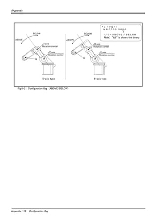
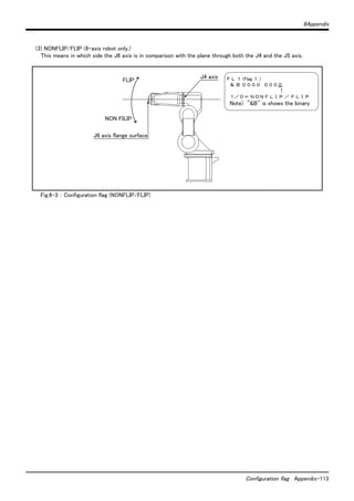


The document provides safety precautions for setting up and maintaining an industrial robot arm. It outlines several key safety measures including: (1) ensuring all teaching and maintenance work is done by specially trained operators, (2) preparing work plans and emergency stop devices, (3) using signs to indicate teaching or maintenance work is in progress, (4) installing safety fences to prevent contact, and (5) inspecting equipment before starting work. The document emphasizes that safety is the top priority for any work involving the robot arm.


