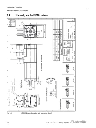
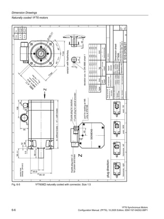
This document provides an overview of 1FT6 synchronous motors. Key points:
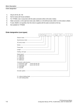
- 1FT6 motors are permanently excited synchronous motors with integrated encoders that can be used with SIMODRIVE 611 and SIMOVERT MASTERDRIVES MC converters.
- Motors are available with natural cooling, forced cooling, or water cooling. Water cooling allows for higher power ratings and protection.
- Benefits include high accuracy, dynamics, efficiency, overload capability, and protection for dirty environments.
- Applications include high-performance machine tools, packaging machines, and other machinery requiring precision, flexibility and dynamics.

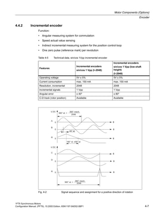
![Motor Description
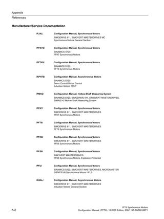
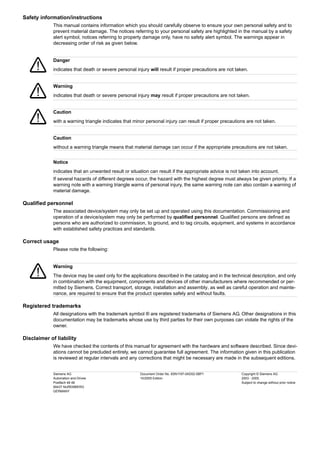
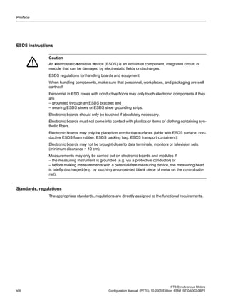
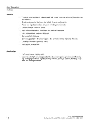
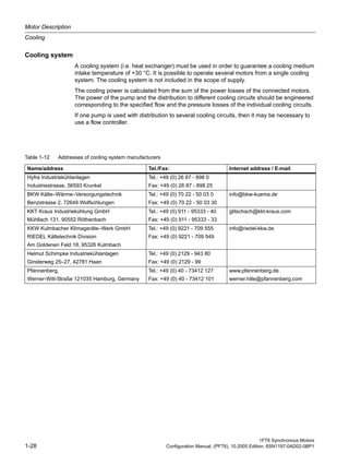
Armature short-circuit braking
1FT6 Synchronous Motors
1-16 Configuration Manual, (PFT6), 10.2005 Edition, 6SN1197-0AD02-0BP1
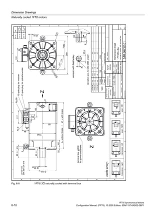
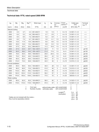
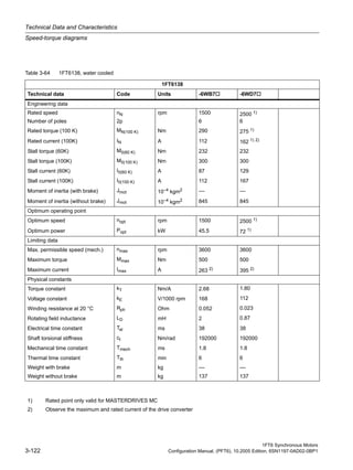
Natural cooling
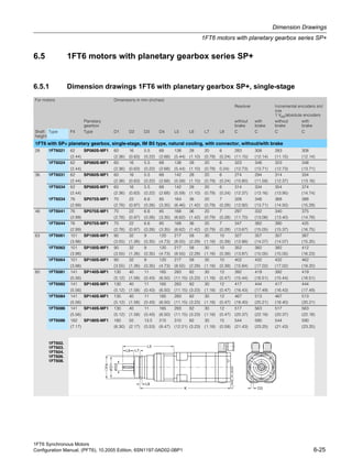
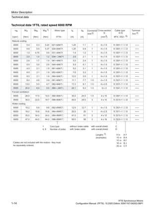
Table 1-2 Resistor braking for the 1FT6 series, shaft heights 28 to 48, natural cooling
Motor type
Braking
resistor
external
Ropt [Ω]
Average braking torque
Mbr rms [Nm] Max.
braking
torque
Mbr max [Nm]
RMS braking current
Ibr rms [A]
without
external
braking resis-
tor
with
external
braking resis-
tor
without
external
braking resis-
tor
with
external
braking resis-
tor
SH 28, SH 36, SH 48, naturally cooled
1FT6021-6AK7 – 1.1 – 1.6 6.8 –
1FT6024-6AK7 – 2.7 – 3.7 8.3 –
1FT6031-4AK7 4.4 2.1 2.3 2.8 6.9 6.4
1FT6034-4AK7 3.7 3.6 4.4 5.5 13 12
1FT6041-4AF7 0.31 6.7 6.8 8.4 10 10
1FT6041-4AK7 2.6 5.8 6.8 8.4 18 17
1FT6044-4AF7 2.0 13 14 17 18 17
1FT6044-4AK7 1.8 10 14 17 37 33
Table 1-3 Resistor braking for the 1FT6 series, shaft heights 63 to 80, naturally cooled
Motor type
Braking
resistor
external
Ropt [Ω]
Average braking torque
Mbr rms [Nm] Max.
braking
torque
Mbr max [Nm]
RMS braking current
Ibr rms [A]
without
external
braking resis-
tor
with
external
braking resis-
tor
without
external
braking resis-
tor
with
external
braking resis-
tor
SH 63 naturally cooled
1FT6061-6AC7 9.2 3.2 3.6 4.5 4.0 3.7
1FT6061-6AF7 9.4 2.7 3.6 4.5 5.7 5.2
1FT6061-6AH7 7.3 2.2 3.6 4.5 8.7 7.8
1FT6061-6AK7 7.1 1.8 3.6 4.5 10 9.3
1FT6062-6AC7 7.7 4.7 5.7 7.0 5.9 5.4
1FT6062-6AF7 6.4 4.0 5.7 7.0 9.0 8.1
1FT6062-6AH7 5.5 3.2 5.7 7.0 13 11
1FT6062-6AK7 4.4 2.6 5.7 7.0 17 15
1FT6064-6AC7 5.9 6.8 9.1 11 9.3 8.5
1FT6064-6AF7 5.0 5.5 9.1 11 14 12
1FT6064-6AH7 3.6 4.4 9.1 11 20 18
1FT6064-6AK7 2.9 3.6 9.1 11 27 24](https://image.slidesharecdn.com/mtr-1ft6-configuration-simodrive-masterdrive-manual-150822210403-lva1-app6891/85/Mtr-1-ft6-configuration-simodrive-masterdrive-manual-26-320.jpg)
![1FT6 Synchronous Motors
Configuration Manual, (PFT6), 10.2005 Edition, 6SN1197-0AD02-0BP1 1-17
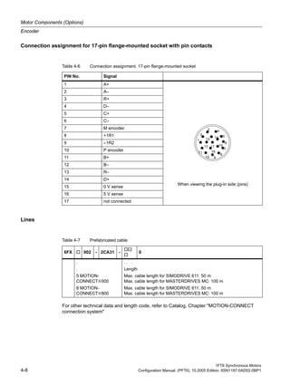
Motor Description
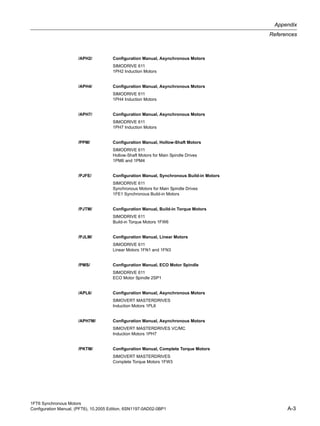
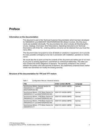
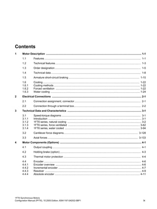
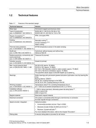
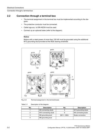
Armature short-circuit braking
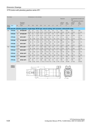
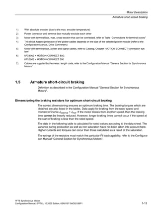
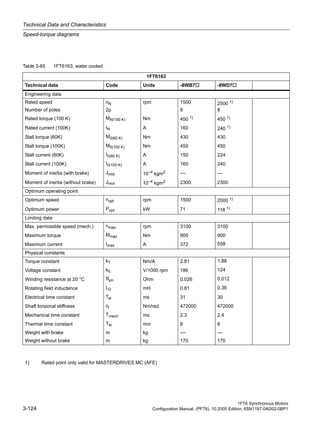
SH 80 naturally cooled
1FT6081-8AC7 6.5 5.1 6.9 8.6 7.8 7.1
1FT6081-8AF7 5.1 4.1 6.9 8.6 12 11
1FT6081-8AH7 3.7 3.2 6.9 8.6 18 16
1FT6081-8AK7 3.4 2.4 6.9 8.6 21 19
1FT6082-8AC7 4.2 6.0 11 13 13 11
1FT6082-8AF7 3.2 5.8 11 13 19 17
1FT6082-8AH7 2.4 3.9 11 13 27 24
1FT6082-8AK7 2.2 3.8 11 13 35 31
1FT6084-8AC7 3.5 11 18 22 19 17
1FT6084-8AF7 2.6 8.2 18 22 28 25
1FT6084-8AH7 1.7 6.8 18 22 44 39
1FT6084-8AK7 1.7 4.7 18 22 49 44
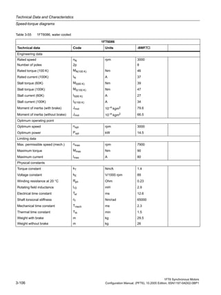
1FT6086-8AC7 2.7 15 27 34 26 23
1FT6086-8AF7 2.1 12 27 34 38 34
1FT6086-8AH7 1.6 10 27 34 57 51
Table 1-3 Resistor braking for the 1FT6 series, shaft heights 63 to 80, naturally cooled
Motor type
Braking
resistor
external
Ropt [Ω]
Average braking torque
Mbr rms [Nm] Max.
braking
torque
Mbr max [Nm]
RMS braking current
Ibr rms [A]
without
external
braking resis-
tor
with
external
braking resis-
tor
without
external
braking resis-
tor
with
external
braking resis-
tor
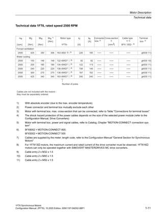
Table 1-4 Resistor braking for the 1FT6 series, shaft heights 100 to 132, naturally cooled
Motor type
Braking
re-
sistor
external
Ropt [Ω]
Average braking torque
Mbr rms [Nm] Max.
braking
torque
Mbr max [Nm]
RMS braking current
Ibr rms [A]
without
external
braking resis-
tor
with
external
braking resis-
tor
without
external
braking resis-
tor
with
external
braking resis-
tor
SH 100 naturally cooled
1FT6102-8AB7 3.9 13 24 30 18 16
1FT6102-8AC7 2.8 11 24 30 25 23
1FT6102-8AF7 2.3 8.1 24 30 35 31
1FT6102-8AH7 1.7 6.5 24 30 51 46
1FT6105-8AB7 2.2 21 43 54 33 29
1FT6105-8AC7 1.7 17 43 54 44 39
1FT6105-8AF7 1.2 13 43 54 65 58
1FT6108-8AB7 1.4 32 71 88 53 47
1FT6108-8AC7 1.2 26 71 88 68 61
1FT6108-8AF7 0.9 21 71 88 99 89](https://image.slidesharecdn.com/mtr-1ft6-configuration-simodrive-masterdrive-manual-150822210403-lva1-app6891/85/Mtr-1-ft6-configuration-simodrive-masterdrive-manual-27-320.jpg)
![Motor Description
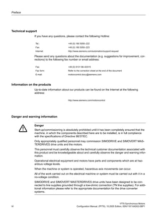
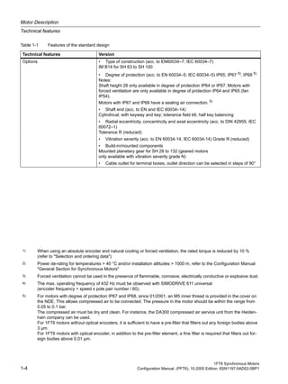
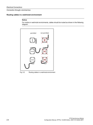
Armature short-circuit braking
1FT6 Synchronous Motors
1-18 Configuration Manual, (PFT6), 10.2005 Edition, 6SN1197-0AD02-0BP1
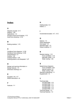
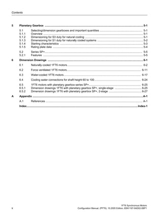
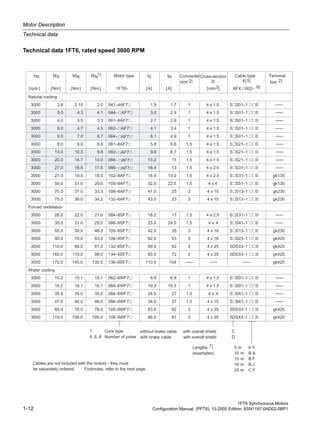
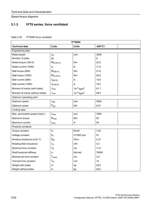
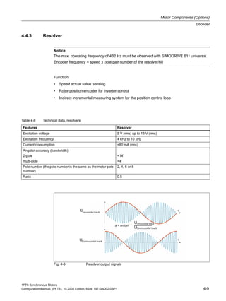
Forced ventilation
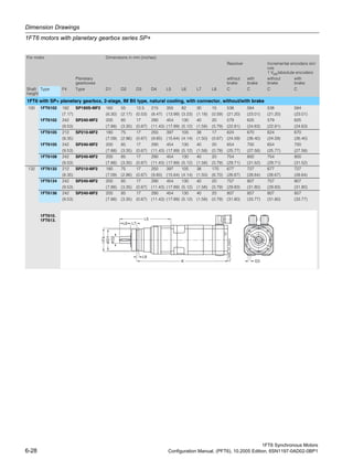
SH 132 naturally cooled
1FT6132-6AB7 1.0 1) 37 83 105 56 50
1FT6132-6AC7 1.2 1) 32 83 105 75 67
1FT6132-6AF7 0.8 1) 23 83 105 110 100
1FT6134-6AB7 1.2 1) 47 110 140 72 65
1FT6134-6AC7 0.9 1) 40 110 140 99 89
1FT6136-6AB7 0.9 1) 55 130 170 91 82
1FT6136-6AC7 0.8 1) 45 130 170 115 105
Table 1-4 Resistor braking for the 1FT6 series, shaft heights 100 to 132, naturally cooled
Motor type
Braking
re-
sistor
external
Ropt [Ω]
Average braking torque
Mbr rms [Nm] Max.
braking
torque
Mbr max [Nm]
RMS braking current
Ibr rms [A]
without
external
braking resis-
tor
with
external
braking resis-
tor
without
external
braking resis-
tor
with
external
braking resis-
tor
1) When utilized to M0 (100 K), a braking resistor must be used in order to prevent partial de-magnetization.
When utilized to M0 (60 K), the additional braking resistor is not required.
Table 1-5 Resistor braking for the 1FT6 series, force-ventilated
Motor type
Braking
resistor
external
Ropt [Ω]
Average braking torque
Mbr rms [Nm] Max.
braking
torque
Mbr max [Nm]
RMS braking current
Ibr rms [A]
without
external
braking resis-
tor
with
external
braking resis-
tor
without
external
braking resis-
tor
with
external
braking resis-
tor
SH 80, force ventilated
1FT6084-8SF7 2.3 8.1 18 22 29 26
1FT6084-8SH7 1.7 6.8 18 22 44 39
1FT6084-8SK7 1.4 4.7 18 22 54 48
1FT6086-8SF7 1.6 11 27 34 42 38
1FT6086-8SH7 1.1 7.5 27 34 61 55
1FT6086-8SK7 1.1 6.6 27 34 74 66
SH 100, force ventilated
1FT6105-8SB7 2.0 21 44 55 35 31
1FT6105-8SC7 1.5 17 44 55 47 42
1FT6105-8SF7 1.2 13 44 55 65 58](https://image.slidesharecdn.com/mtr-1ft6-configuration-simodrive-masterdrive-manual-150822210403-lva1-app6891/85/Mtr-1-ft6-configuration-simodrive-masterdrive-manual-28-320.jpg)
![1FT6 Synchronous Motors
Configuration Manual, (PFT6), 10.2005 Edition, 6SN1197-0AD02-0BP1 1-19
Motor Description
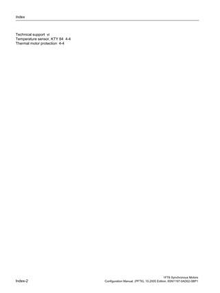
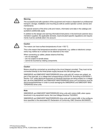
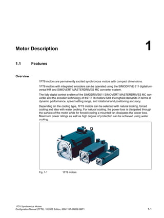
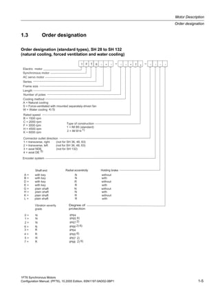
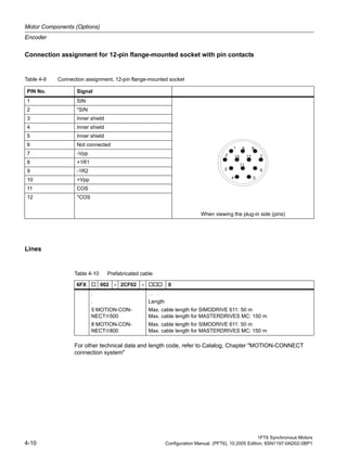
Armature short-circuit braking
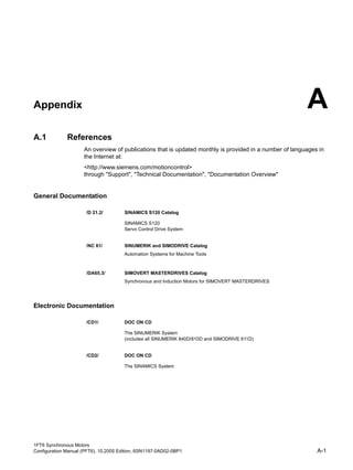
1FT6105-8SH7 0.9 10 44 55 96 86
1FT6108-8SB7 1.2 33 71 88 58 52
1FT6108-8SC7 0.9 27 71 88 77 69
1FT6108-8SF7 0.6 20 71 88 115 103
SH 132, force ventilated
1FT6132-6SB7 1.2 36 1) 83 105 63 57
1FT6132-6SC7 1.0 30 1) 83 105 83 74
1FT6132-6SF7 0.7 23 1) 83 105 120 110
1FT6134-6SB7 0.9 49 1) 110 140 81 73
1FT6134-6SC7 0.8 40 1) 110 140 105 95
1FT6134-6SF7 0.6 30 1) 110 140 150 140
1FT6136-6SB7 0.8 54 1) 130 170 99 88
1FT6136-6SC7 0.6 43 1) 130 170 130 120
1FT6136-6SF7 0.5 33 1) 130 170 190 170
SH 160, force ventilated
1FT6163-8SB7 0.3 2) – 380 490 – 270
1FT6163-8SD7 0.25 2) – 380 490 – 390
1FT6168-8SB7 0.27 2) – 530 680 – 340
Table 1-5 Resistor braking for the 1FT6 series, force-ventilated
Motor type
Braking
resistor
external
Ropt [Ω]
Average braking torque
Mbr rms [Nm] Max.
braking
torque
Mbr max [Nm]
RMS braking current
Ibr rms [A]
without
external
braking resis-
tor
with
external
braking resis-
tor
without
external
braking resis-
tor
with
external
braking resis-
tor
1) When utilized acc. to M0 (100 K), a series braking resistor must be used in order to prevent partial de-magnetiza-
tion.
When utilized according to M0 (60 K), the additional braking resistor is not required.
2) In order to prevent that the motors are de-magnetized, when short-circuit braking from the rated speed, the above
specified supplementary resistors must be connected in series.](https://image.slidesharecdn.com/mtr-1ft6-configuration-simodrive-masterdrive-manual-150822210403-lva1-app6891/85/Mtr-1-ft6-configuration-simodrive-masterdrive-manual-29-320.jpg)
![Motor Description
Armature short-circuit braking
1FT6 Synchronous Motors
1-20 Configuration Manual, (PFT6), 10.2005 Edition, 6SN1197-0AD02-0BP1
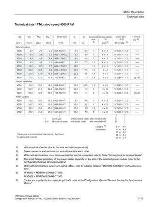
Water cooling
Table 1-6 Resistor braking for the 1FT6 series, water cooling
Motor type
Braking
resistor
external
Ropt [Ω]
Average braking torque
Mbr rms [Nm] Max.
braking
torque
Mbr max [Nm]
RMS braking current
Ibr rms [A]
without
external
braking resis-
tor
with
external
braking resis-
tor
without
external
braking resis-
tor
Max.
braking
torque
Mbr max [Nm]
SH 60, water cooling
1FT6062-6WF7 6.4 4.0 5.7 7.0 9 8.1
1FT6062-6WH7 5.5 3.2 5.7 7.0 13 11
1FT6062-6WK7 4.4 2.6 5.7 7.0 17 15
1FT6064-6WF7 5.0 5.5 9.1 11 14 12
1FT6064-6WH7 3.6 4.4 9.1 11 20 18
1FT6064-6WK7 2.9 3.6 9.1 11 27 24
SH 80, water cooling
1FT6084-8WF7 2.3 8.1 18 22 29 26
1FT6084-8WH7 1.6 6.5 18 22 44 40
1FT6084-8WK7 1.4 4.7 18 22 54 48
1FT6086-8WF7 1.6 11 27 34 42 38
1FT6086-8WH7 1.1 7.5 27 34 61 55
1FT6086-8WK7 1.1 6.6 27 34 74 66
SH 100, water cooling
1FT6105- WC7 0.8 17 44 55 65 58
1FT6105- WF7 0.6 14 44 55 96 86
1FT6108- WB7 1.2 33 71 88 58 52
1FT6108- WC7 0.9 27 71 88 77 69
1FT6108- WF7 0.6 21 71 88 115 103
SH 132, water cooling
1FT6132-6WB7 0.9 40 1) 85 105 72 65
1FT6132-6WD7 0.7 27 1) 85 105 115 100
1FT6134-6WB7 0.7 47 1) 110 140 92 82
1FT6134-6WD7 0.5 33 1) 110 140 150 140
1FT6136-6WB7 0.6 56 1) 130 170 115 100
1FT6136-6WD7 0.35 40 1) 130 170 200 180
1FT6138-6WB7 0.42 69 1) 170 220 150 140
1FT6138-6WD7 0.32 50 1) 170 220 240 210
SH 160, water cooling
1FT6163-8WB7 0.3 2) – 380 490 – 270](https://image.slidesharecdn.com/mtr-1ft6-configuration-simodrive-masterdrive-manual-150822210403-lva1-app6891/85/Mtr-1-ft6-configuration-simodrive-masterdrive-manual-30-320.jpg)
![1FT6 Synchronous Motors
Configuration Manual, (PFT6), 10.2005 Edition, 6SN1197-0AD02-0BP1 1-21
Motor Description
Armature short-circuit braking
1FT6163-8WD7 0.25 2) – 380 490 – 390
1FT6168-8WB7 0.27 2) – 530 680 – 340
Table 1-6 Resistor braking for the 1FT6 series, water cooling
Motor type
Braking
resistor
external
Ropt [Ω]
Average braking torque
Mbr rms [Nm] Max.
braking
torque
Mbr max [Nm]
RMS braking current
Ibr rms [A]
without
external
braking resis-
tor
with
external
braking resis-
tor
without
external
braking resis-
tor
Max.
braking
torque
Mbr max [Nm]
1) When utilized acc. to M0 (100 K), a series braking resistor must be used in order to prevent partial de-magnetiza-
tion.
When utilized according to M0 (60 K), the additional braking resistor is not required.
2) It is absolutely prohibited to short-circuit the winding when using smaller supplementary resistors than those speci-
fied. When braking from the rated speed, the resistors listed prevent partial de-magnetization of the rotor.](https://image.slidesharecdn.com/mtr-1ft6-configuration-simodrive-masterdrive-manual-150822210403-lva1-app6891/85/Mtr-1-ft6-configuration-simodrive-masterdrive-manual-31-320.jpg)
![1FT6 Synchronous Motors
Configuration Manual, (PFT6), 10.2005 Edition, 6SN1197-0AD02-0BP1 1-23
Motor Description
Cooling
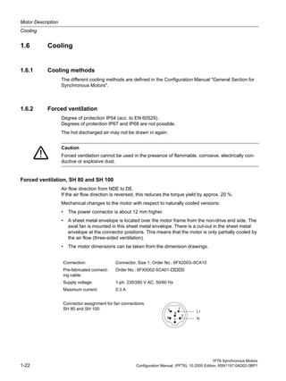
Forced ventilation, SH 132
Air flow direction from DE to NDE.
The air is blow through the enclosure corners of the extruded profile using a mounted radial
fan.
Forced ventilation, SH 160
Air flow direction from DE to NDE.
The air is blow through the enclosure corners of the extruded profile using a mounted radial
fan.
Minimum clearance between parts and components mounted by the customer and the air dis-
charge opening
The following minimum clearance must be maintained between parts and components
mounted by the customer and the air discharge opening:
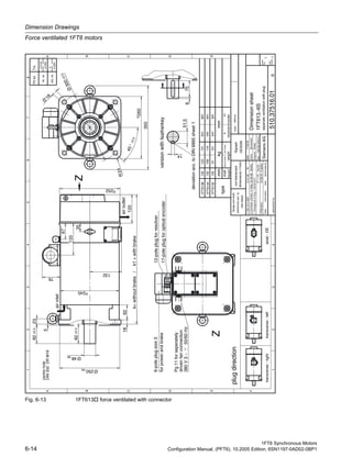
Connection: via terminal box
Supply voltage: 3-ph. 400/480 V AC, 50/60 Hz
Maximum current: 0.4 A
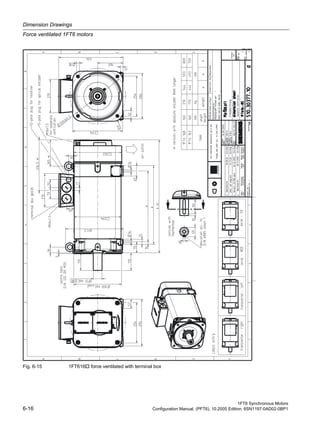
Connection: via terminal box
Supply voltage: 3-ph. 400/480 V AC, 50/60 Hz
Maximum current: 0.8 A
Table 1-7 Minimum clearance to parts and components mounted by the customer
Shaft height [mm] Minimum clearance [mm]
80 20
100 30
132 60
160 80](https://image.slidesharecdn.com/mtr-1ft6-configuration-simodrive-masterdrive-manual-150822210403-lva1-app6891/85/Mtr-1-ft6-configuration-simodrive-masterdrive-manual-33-320.jpg)
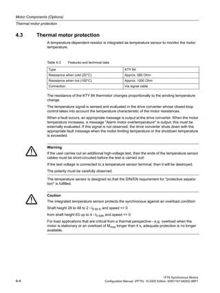
![Motor Description
Cooling
1FT6 Synchronous Motors
1-24 Configuration Manual, (PFT6), 10.2005 Edition, 6SN1197-0AD02-0BP1
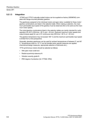
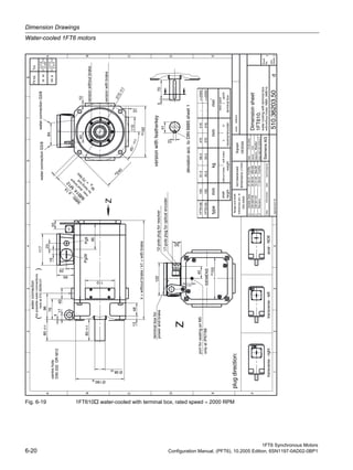
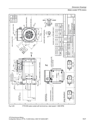
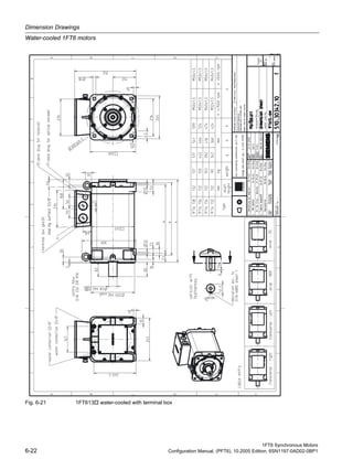
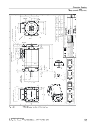
1.6.3 Water cooling
The power loss generated by the motor is dissipated using a water cooling system. The
machinery construction company must connect up a cooling system (e.g. heat exchanger).
The rated motor torques, specified in the motor data sheets, apply for water-cooled operation
and a water intake temperature of < 30 °C.
The cooling medium must be pre-cleaned and filtered in order to prevent the cooling circuit
from becoming blocked. The maximum permissible particle size after filtering is 100 µm.
Cooling circuit
Pressure drop, intake/return: < 0.1 bar
Notice
If the motor is operated without water cooling, then the rated motor torque is reduced as a
function of the heat losses which can be dissipated by convection and radiation. In this case,
the data for naturally cooled operation apply.
Note
It is not possible to retrofit a motor for water cooling.
Notice
If current is flowing through the motor, then the cooling circuit must be activated.
Table 1-8 Technical data for the cooling circuit
Motor type
Water flow rate
[l]
Max. permissible
pressure
[bar]
Flow rate
[l/min]
1FT6062 0.2 2.5 5
1FT6064 0.26 2.5 5
1FT6084 0.5 2.5 5
1FT6086 0.6 2.5 5
1FT6105 1.1 2.5 5
1FT6108 1.5 2.5 5
1FT6132 2.1 6.0 8
1FT6134 2.4 6.0 8
1FT6136 2.7 6.0 8
1FT6138 3.1 6.0 8
1FT6163 4.7 6.0 10
1FT6168 5.7 6.0 10](https://image.slidesharecdn.com/mtr-1ft6-configuration-simodrive-masterdrive-manual-150822210403-lva1-app6891/85/Mtr-1-ft6-configuration-simodrive-masterdrive-manual-34-320.jpg)
![1FT6 Synchronous Motors
Configuration Manual, (PFT6), 10.2005 Edition, 6SN1197-0AD02-0BP1 1-25
Motor Description
Cooling
Materials used in the cooling circuits
The anti-corrosion additives used should be harmonized with the cooling system manufac-
turer - i.e. the materials of the motor cooler and the materials of the fittings and cooling
medium hoses listed in Table.
Cooling medium and anti-corrosion protection
We recommend that an anti-corrosion agent is added to water as cooling-medium (e.g. Anti-
frogen N from the Hoechst Company or Tyfocor from Tyforop Chemie GmbH, refer to the
Table below).
Observe the specifications of the anti-corrosion agent manufacturer regarding the ratio of
water to anti-corrosion agent.
For Tyfocor, the ratio of 75 % water and 25 % anti-corrosion agent should not be exceeded.
When using another cooling medium (e.g. oil, cooling-lubricating medium), de-rating may be
required in order that the thermal motor limit is not exceeded. The de-rating can be deter-
mined using the following data:
The enquiry must be sent to the manufacturer's plant (Hotline).
The motor power still does not have to be reduced for oil-water mixtures with less than 10 %.
Table 1-9 Materials used in the motor cooling circuit
Motor type
Bearing end
shield
Enclosure Sealing agent Connecting plate
1FT606
1FT608
1FT610
Aluminum Aluminum Type Terostat Stainless steel
1FT613
1FT616
Gray cast iron Aluminum Type Terostat –––
Notice
It is not permissible that ice forms in the cooling circuit, neither during transport, nor in opera-
tion or during storage.
The checking and change intervals for the cooling medium should be harmonized with the
companies supplying the anti-corrosion agent and the cooling system.
Specific density: ρ [kg/m3
]
Specific thermal capacitance: cp [J/(kg K)]
Intake temperature: tv [°C]
Flow quantity: v [l/min]
Note
Different anti-corrosion agents should not be mixed.](https://image.slidesharecdn.com/mtr-1ft6-configuration-simodrive-masterdrive-manual-150822210403-lva1-app6891/85/Mtr-1-ft6-configuration-simodrive-masterdrive-manual-35-320.jpg)
![1FT6 Synchronous Motors
Configuration Manual, (PFT6), 10.2005 Edition, 6SN1197-0AD02-0BP1 1-27
Motor Description
Cooling
Cooling powers to be dissipated
The values specified in the table refer to a cooling medium temperature of 30 °C and maxi-
mum speed in S1 duty.
Table 1-11 Cooling powers to be dissipated
Motor type
To be dissipated
cooling power [W]
1FT6062–6WF7 600
1FT6062–6WH7 650
1FT6062–6WK7 700
1FT6064–6WF7 800
1FT6064–6WH7 850
1FT6064–6WK7 900
1FT6084–8WF7 1500
1FT6084–8WH7 1900
1FT6084–8WK7 2200
1FT6086–8WF7 1800
1FT6086–8WH7 2000
1FT6086–8WK7 2400
1FT6105–8WC7 2000
1FT6105–8WF7 2100
1FT6108–8WB7 1900
1FT6108–8WC7 2100
1FT6108–8WF7 2300
1FT6132–6WB7 2600
1FT6132–6WD7 2700
1FT6134–6WB7 2700
1FT6134–6WD7 3100
1FT6136–6WB7 3300
1FT6136–6WD7 3600
1FT6138–6WB7 3600
1FT6138–6WD7 4000
1FT6163–8WB7 4500
1FT6163–8WD7 6000
1FT6168–8WB7 7500](https://image.slidesharecdn.com/mtr-1ft6-configuration-simodrive-masterdrive-manual-150822210403-lva1-app6891/85/Mtr-1-ft6-configuration-simodrive-masterdrive-manual-37-320.jpg)

![1FT6 Synchronous Motors
Configuration Manual, (PFT6), 10.2005 Edition, 6SN1197-0AD02-0BP1 2-3
Electrical Connections
Connection through a terminal box
Table 2-2 Connections for the terminal box
Terminal
box type
Cable entry
Max.
outer
cable
diame-
ter 3)
[mm]
RMS
current
per ter-
minal
[A]1)
No. of
main
termi-
nals
Max.
cross-sec-
tion
per terminal
Ground
connec-
tion
Tighten-
ing
torque
[Nm]
Brake con-
nection 2)
gk130 1 x Pg29 / 1 x Pg9 30 36 3 x M4 1 x 6 mm2 M4 0.8 - 1.2 1.5 mm2
gk230 1 x Pg29 / 1 x Pg9 30 66 3 x M5 1 x 16 mm2 M4 0.8 - 1.2 1.5 mm2
gk420 1 x Pg36 37 104 4 x M10 1 x 35 mm2 M6 2.7 - 4 1.5 mm2
gk630 2 x M32 x 1.5 25 112 3 x M10 2 x 16 mm2 M10 9 - 13 –––
gk630 2 x M40 x 1.5 32 176 3 x M10 2 x 35 mm2 M10 9 - 13 –––
gk630 2 x M50 x 1.5 41 209 3 x M10 2 x 50 mm2 M10 9 - 13 –––
1) Data according to DIN EN 60204-1 (routing type C, ambient temperature 40 °C)
2) BD1+/BD2- (terminal strip, only for versions with brake)
3) Dependent on the seal used](https://image.slidesharecdn.com/mtr-1ft6-configuration-simodrive-masterdrive-manual-150822210403-lva1-app6891/85/Mtr-1-ft6-configuration-simodrive-masterdrive-manual-41-320.jpg)
![1FT6 Synchronous Motors
Configuration Manual, (PFT6), 10.2005 Edition, 6SN1197-0AD02-0BP1 3-3
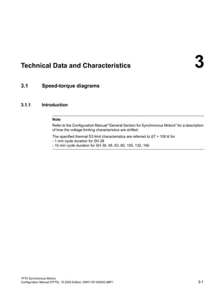
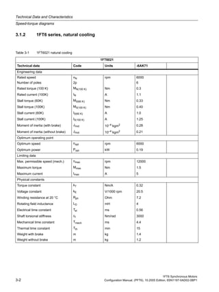
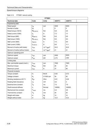
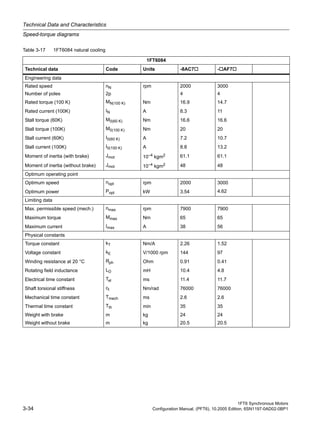
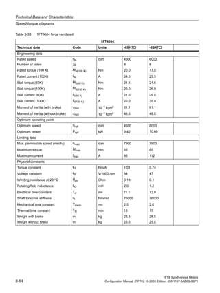
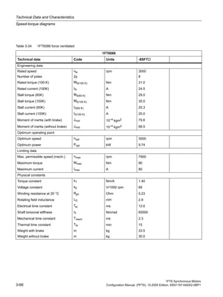
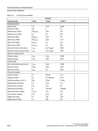
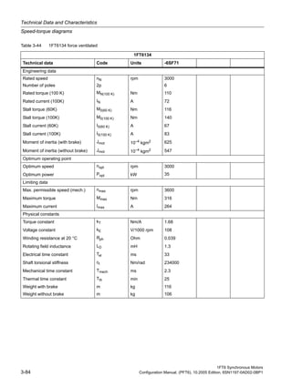
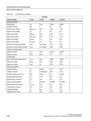
Technical Data and Characteristics
Speed-torque diagrams
Fig. 3-1 Speed-torque diagram 1FT6021-6AK71
[a] MASTERDRIVES MC, VDC link = 540 V (DC), VMot = 340 Vrms
[b] SIMODRIVE 611 (UE), VDC link = 540 V (DC) and MASTERDRIVES MC (AFE), VDC link = 600 V (DC), VMot = 380
Vrms
[c] SIMODRIVE 611 (ER), VDC link = 600 V (DC), VMot = 425 Vrms](https://image.slidesharecdn.com/mtr-1ft6-configuration-simodrive-masterdrive-manual-150822210403-lva1-app6891/85/Mtr-1-ft6-configuration-simodrive-masterdrive-manual-45-320.jpg)

![1FT6 Synchronous Motors
Configuration Manual, (PFT6), 10.2005 Edition, 6SN1197-0AD02-0BP1 3-5
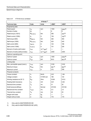
Technical Data and Characteristics
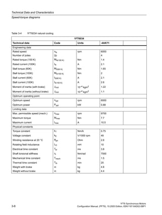
Speed-torque diagrams
Fig. 3-2 Speed-torque diagram 1FT6024-6AK71
[a] MASTERDRIVES MC, VDC link = 540 V (DC), VMot = 340 Vrms
[b] SIMODRIVE 611 (UE), VDC link = 540 V (DC) and MASTERDRIVES MC (AFE), VDC link = 600 V (DC), VMot = 380
Vrms
[c] SIMODRIVE 611 (ER), VDC link = 600 V (DC), VMot = 425 Vrms](https://image.slidesharecdn.com/mtr-1ft6-configuration-simodrive-masterdrive-manual-150822210403-lva1-app6891/85/Mtr-1-ft6-configuration-simodrive-masterdrive-manual-47-320.jpg)

![1FT6 Synchronous Motors
Configuration Manual, (PFT6), 10.2005 Edition, 6SN1197-0AD02-0BP1 3-7
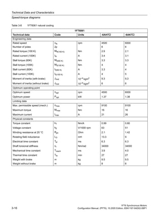
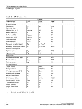
Technical Data and Characteristics
Speed-torque diagrams
Fig. 3-3 Speed-torque diagram 1FT6031-4AK71
[a] MASTERDRIVES MC, VDC link = 540 V (DC), VMot = 340 Vrms
[b] SIMODRIVE 611 (UE), VDC link = 540 V (DC) and MASTERDRIVES MC (AFE), VDC link = 600 V (DC), VMot = 380
Vrms
[c] SIMODRIVE 611 (ER), VDC link = 600 V (DC), VMot = 425 Vrms](https://image.slidesharecdn.com/mtr-1ft6-configuration-simodrive-masterdrive-manual-150822210403-lva1-app6891/85/Mtr-1-ft6-configuration-simodrive-masterdrive-manual-49-320.jpg)
![1FT6 Synchronous Motors
Configuration Manual, (PFT6), 10.2005 Edition, 6SN1197-0AD02-0BP1 3-9
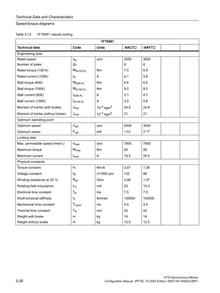
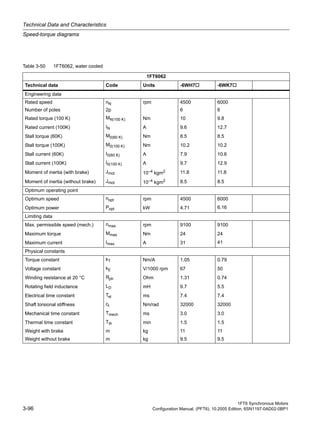
Technical Data and Characteristics
Speed-torque diagrams
Fig. 3-4 Speed-torque diagram 1FT6034
[a] MASTERDRIVES MC, VDC link = 540 V (DC), VMot = 340 Vrms
[b] SIMODRIVE 611 (UE), VDC link = 540 V (DC) and MASTERDRIVES MC (AFE), VDC link = 600 V (DC), VMot = 380
Vrms
[c] SIMODRIVE 611 (ER), VDC link = 600 V (DC), VMot = 425 Vrms](https://image.slidesharecdn.com/mtr-1ft6-configuration-simodrive-masterdrive-manual-150822210403-lva1-app6891/85/Mtr-1-ft6-configuration-simodrive-masterdrive-manual-51-320.jpg)

![1FT6 Synchronous Motors
Configuration Manual, (PFT6), 10.2005 Edition, 6SN1197-0AD02-0BP1 3-11
Technical Data and Characteristics
Speed-torque diagrams
Fig. 3-5 Speed-torque diagram 1FT6041-4AF71
Fig. 3-6 Speed-torque diagram 1FT6041-4AK71
[a] MASTERDRIVES MC, VDC link = 540 V (DC), VMot = 340 Vrms
[b] SIMODRIVE 611 (UE), VDC link = 540 V (DC) and MASTERDRIVES MC (AFE), VDC link = 600 V (DC), VMot = 380
Vrms
[c] SIMODRIVE 611 (ER), VDC link = 600 V (DC), VMot = 425 Vrms](https://image.slidesharecdn.com/mtr-1ft6-configuration-simodrive-masterdrive-manual-150822210403-lva1-app6891/85/Mtr-1-ft6-configuration-simodrive-masterdrive-manual-53-320.jpg)

![1FT6 Synchronous Motors
Configuration Manual, (PFT6), 10.2005 Edition, 6SN1197-0AD02-0BP1 3-13
Technical Data and Characteristics
Speed-torque diagrams
Fig. 3-7 Speed-torque diagram 1FT6044- AF71
Fig. 3-8 Speed-torque diagram 1FT6044-4AK71
[a] MASTERDRIVES MC, VDC link = 540 V (DC), VMot = 340 Vrms
[b] SIMODRIVE 611 (UE), VDC link = 540 V (DC) and MASTERDRIVES MC (AFE), VDC link = 600 V (DC), VMot = 380
Vrms
[c] SIMODRIVE 611 (ER), VDC link = 600 V (DC), VMot = 425 Vrms](https://image.slidesharecdn.com/mtr-1ft6-configuration-simodrive-masterdrive-manual-150822210403-lva1-app6891/85/Mtr-1-ft6-configuration-simodrive-masterdrive-manual-55-320.jpg)

![1FT6 Synchronous Motors
Configuration Manual, (PFT6), 10.2005 Edition, 6SN1197-0AD02-0BP1 3-15
Technical Data and Characteristics
Speed-torque diagrams
Fig. 3-9 Speed-torque diagram 1FT6061-6AC7
Fig. 3-10 Speed-torque diagram 1FT6061-6AF7
[a] MASTERDRIVES MC, VDC link = 540 V (DC), VMot = 340 Vrms
[b] SIMODRIVE 611 (UE), VDC link = 540 V (DC) and MASTERDRIVES MC (AFE), VDC link = 600 V (DC), VMot = 380
Vrms
[c] SIMODRIVE 611 (ER), VDC link = 600 V (DC), VMot = 425 Vrms](https://image.slidesharecdn.com/mtr-1ft6-configuration-simodrive-masterdrive-manual-150822210403-lva1-app6891/85/Mtr-1-ft6-configuration-simodrive-masterdrive-manual-57-320.jpg)
![1FT6 Synchronous Motors
Configuration Manual, (PFT6), 10.2005 Edition, 6SN1197-0AD02-0BP1 3-17
Technical Data and Characteristics
Speed-torque diagrams
Fig. 3-11 Speed-torque diagram 1FT6061-6AH7
Fig. 3-12 Speed-torque diagram 1FT6061-6AK7
[a] MASTERDRIVES MC, VDC link = 540 V (DC), VMot = 340 Vrms
[b] SIMODRIVE 611 (UE), VDC link = 540 V (DC) and MASTERDRIVES MC (AFE), VDC link = 600 V (DC), VMot = 380
Vrms
[c] SIMODRIVE 611 (ER), VDC link = 600 V (DC), VMot = 425 Vrms](https://image.slidesharecdn.com/mtr-1ft6-configuration-simodrive-masterdrive-manual-150822210403-lva1-app6891/85/Mtr-1-ft6-configuration-simodrive-masterdrive-manual-59-320.jpg)

![1FT6 Synchronous Motors
Configuration Manual, (PFT6), 10.2005 Edition, 6SN1197-0AD02-0BP1 3-19
Technical Data and Characteristics
Speed-torque diagrams
Fig. 3-13 Speed-torque diagram 1FT6062-6AC7
Fig. 3-14 Speed-torque diagram 1FT6062-6AF7
[a] MASTERDRIVES MC, VDC link = 540 V (DC), VMot = 340 Vrms
[b] SIMODRIVE 611 (UE), VDC link = 540 V (DC) and MASTERDRIVES MC (AFE), VDC link = 600 V (DC), VMot = 380
Vrms
[c] SIMODRIVE 611 (ER), VDC link = 600 V (DC), VMot = 425 Vrms](https://image.slidesharecdn.com/mtr-1ft6-configuration-simodrive-masterdrive-manual-150822210403-lva1-app6891/85/Mtr-1-ft6-configuration-simodrive-masterdrive-manual-61-320.jpg)

![1FT6 Synchronous Motors
Configuration Manual, (PFT6), 10.2005 Edition, 6SN1197-0AD02-0BP1 3-21
Technical Data and Characteristics
Speed-torque diagrams
Fig. 3-15 Speed-torque diagram 1FT6062-6AH7
Fig. 3-16 Speed-torque diagram 1FT6062-6AK7
[a] MASTERDRIVES MC, VDC link = 540 V (DC), VMot = 340 Vrms
[b] SIMODRIVE 611 (UE), VDC link = 540 V (DC) and MASTERDRIVES MC (AFE), VDC link = 600 V (DC), VMot = 380
Vrms
[c] SIMODRIVE 611 (ER), VDC link = 600 V (DC), VMot = 425 Vrms](https://image.slidesharecdn.com/mtr-1ft6-configuration-simodrive-masterdrive-manual-150822210403-lva1-app6891/85/Mtr-1-ft6-configuration-simodrive-masterdrive-manual-63-320.jpg)

![1FT6 Synchronous Motors
Configuration Manual, (PFT6), 10.2005 Edition, 6SN1197-0AD02-0BP1 3-23
Technical Data and Characteristics
Speed-torque diagrams
Fig. 3-17 Speed-torque diagram 1FT6064-6AC7
Fig. 3-18 Speed-torque diagram 1FT6064-6AF7
[a] MASTERDRIVES MC, VDC link = 540 V (DC), VMot = 340 Vrms
[b] SIMODRIVE 611 (UE), VDC link = 540 V (DC) and MASTERDRIVES MC (AFE), VDC link = 600 V (DC), VMot = 380
Vrms
[c] SIMODRIVE 611 (ER), VDC link = 600 V (DC), VMot = 425 Vrms](https://image.slidesharecdn.com/mtr-1ft6-configuration-simodrive-masterdrive-manual-150822210403-lva1-app6891/85/Mtr-1-ft6-configuration-simodrive-masterdrive-manual-65-320.jpg)

![1FT6 Synchronous Motors
Configuration Manual, (PFT6), 10.2005 Edition, 6SN1197-0AD02-0BP1 3-25
Technical Data and Characteristics
Speed-torque diagrams
Fig. 3-19 Speed-torque diagram 1FT6064-6AH7
Fig. 3-20 Speed-torque diagram 1FT6064-6AK7
[a] MASTERDRIVES MC, VDC link = 540 V (DC), VMot = 340 Vrms
[b] SIMODRIVE 611 (UE), VDC link = 540 V (DC) and MASTERDRIVES MC (AFE), VDC link = 600 V (DC), VMot = 380
Vrms
[c] SIMODRIVE 611 (ER), VDC link = 600 V (DC), VMot = 425 Vrms](https://image.slidesharecdn.com/mtr-1ft6-configuration-simodrive-masterdrive-manual-150822210403-lva1-app6891/85/Mtr-1-ft6-configuration-simodrive-masterdrive-manual-67-320.jpg)
![1FT6 Synchronous Motors
Configuration Manual, (PFT6), 10.2005 Edition, 6SN1197-0AD02-0BP1 3-27
Technical Data and Characteristics
Speed-torque diagrams
Fig. 3-21 Speed-torque diagram 1FT6081-8AC7
Fig. 3-22 Speed-torque diagram 1FT6081-8AF7
[a] MASTERDRIVES MC, VDC link = 540 V (DC), VMot = 340 Vrms
[b] SIMODRIVE 611 (UE), VDC link = 540 V (DC) and MASTERDRIVES MC (AFE), VDC link = 600 V (DC), VMot = 380
Vrms
[c] SIMODRIVE 611 (ER), VDC link = 600 V (DC), VMot = 425 Vrms](https://image.slidesharecdn.com/mtr-1ft6-configuration-simodrive-masterdrive-manual-150822210403-lva1-app6891/85/Mtr-1-ft6-configuration-simodrive-masterdrive-manual-69-320.jpg)
![1FT6 Synchronous Motors
Configuration Manual, (PFT6), 10.2005 Edition, 6SN1197-0AD02-0BP1 3-29
Technical Data and Characteristics
Speed-torque diagrams
Fig. 3-23 Speed-torque diagram 1FT6081-8AH7
Fig. 3-24 Speed-torque diagram 1FT6081-8AH7
[a] MASTERDRIVES MC, VDC link = 540 V (DC), VMot = 340 Vrms
[b] SIMODRIVE 611 (UE), VDC link = 540 V (DC) and MASTERDRIVES MC (AFE), VDC link = 600 V (DC), VMot = 380
Vrms
[c] SIMODRIVE 611 (ER), VDC link = 600 V (DC), VMot = 425 Vrms](https://image.slidesharecdn.com/mtr-1ft6-configuration-simodrive-masterdrive-manual-150822210403-lva1-app6891/85/Mtr-1-ft6-configuration-simodrive-masterdrive-manual-71-320.jpg)

![1FT6 Synchronous Motors
Configuration Manual, (PFT6), 10.2005 Edition, 6SN1197-0AD02-0BP1 3-31
Technical Data and Characteristics
Speed-torque diagrams
Fig. 3-25 Speed-torque diagram 1FT6082-8AC7
Fig. 3-26 Speed-torque diagram 1FT6082-8AF7
[a] MASTERDRIVES MC, VDC link = 540 V (DC), VMot = 340 Vrms
[b] SIMODRIVE 611 (UE), VDC link = 540 V (DC) and MASTERDRIVES MC (AFE), VDC link = 600 V (DC), VMot = 380
Vrms
[c] SIMODRIVE 611 (ER), VDC link = 600 V (DC), VMot = 425 Vrms](https://image.slidesharecdn.com/mtr-1ft6-configuration-simodrive-masterdrive-manual-150822210403-lva1-app6891/85/Mtr-1-ft6-configuration-simodrive-masterdrive-manual-73-320.jpg)

![1FT6 Synchronous Motors
Configuration Manual, (PFT6), 10.2005 Edition, 6SN1197-0AD02-0BP1 3-33
Technical Data and Characteristics
Speed-torque diagrams
Fig. 3-27 Speed-torque diagram 1FT6082-8AH7
Fig. 3-28 Speed-torque diagram 1FT6082-8AK7
[a] MASTERDRIVES MC, VDC link = 540 V (DC), VMot = 340 Vrms
[b] SIMODRIVE 611 (UE), VDC link = 540 V (DC) and MASTERDRIVES MC (AFE), VDC link = 600 V (DC), VMot = 380
Vrms
[c] SIMODRIVE 611 (ER), VDC link = 600 V (DC), VMot = 425 Vrms](https://image.slidesharecdn.com/mtr-1ft6-configuration-simodrive-masterdrive-manual-150822210403-lva1-app6891/85/Mtr-1-ft6-configuration-simodrive-masterdrive-manual-75-320.jpg)
![1FT6 Synchronous Motors
Configuration Manual, (PFT6), 10.2005 Edition, 6SN1197-0AD02-0BP1 3-35
Technical Data and Characteristics
Speed-torque diagrams
Fig. 3-29 Speed-torque diagram 1FT6084-8AC7
Fig. 3-30 Speed-torque diagram 1FT6084- AF7
[a] MASTERDRIVES MC, VDC link = 540 V (DC), VMot = 340 Vrms
[b] SIMODRIVE 611 (UE), VDC link = 540 V (DC) and MASTERDRIVES MC (AFE), VDC link = 600 V (DC), VMot = 380
Vrms
[c] SIMODRIVE 611 (ER), VDC link = 600 V (DC), VMot = 425 Vrms](https://image.slidesharecdn.com/mtr-1ft6-configuration-simodrive-masterdrive-manual-150822210403-lva1-app6891/85/Mtr-1-ft6-configuration-simodrive-masterdrive-manual-77-320.jpg)

![1FT6 Synchronous Motors
Configuration Manual, (PFT6), 10.2005 Edition, 6SN1197-0AD02-0BP1 3-37
Technical Data and Characteristics
Speed-torque diagrams
Fig. 3-31 Speed-torque diagram 1FT6084- AH7
Fig. 3-32 Speed-torque diagram 1FT6084- AK7
[a] MASTERDRIVES MC, VDC link = 540 V (DC), VMot = 340 Vrms
[b] SIMODRIVE 611 (UE), VDC link = 540 V (DC) and MASTERDRIVES MC (AFE), VDC link = 600 V (DC), VMot = 380
Vrms
[c] SIMODRIVE 611 (ER), VDC link = 600 V (DC), VMot = 425 Vrms](https://image.slidesharecdn.com/mtr-1ft6-configuration-simodrive-masterdrive-manual-150822210403-lva1-app6891/85/Mtr-1-ft6-configuration-simodrive-masterdrive-manual-79-320.jpg)

![1FT6 Synchronous Motors
Configuration Manual, (PFT6), 10.2005 Edition, 6SN1197-0AD02-0BP1 3-39
Technical Data and Characteristics
Speed-torque diagrams
Fig. 3-33 Speed-torque diagram 1FT6086-8AC7
[a] MASTERDRIVES MC, VDC link = 540 V (DC), VMot = 340 Vrms
[b] SIMODRIVE 611 (UE), VDC link = 540 V (DC) and MASTERDRIVES MC (AFE), VDC link = 600 V (DC), VMot = 380
Vrms
[c] SIMODRIVE 611 (ER), VDC link = 600 V (DC), VMot = 425 Vrms](https://image.slidesharecdn.com/mtr-1ft6-configuration-simodrive-masterdrive-manual-150822210403-lva1-app6891/85/Mtr-1-ft6-configuration-simodrive-masterdrive-manual-81-320.jpg)

![1FT6 Synchronous Motors
Configuration Manual, (PFT6), 10.2005 Edition, 6SN1197-0AD02-0BP1 3-41
Technical Data and Characteristics
Speed-torque diagrams
Fig. 3-34 Speed-torque diagram 1FT6086- AF7
Fig. 3-35 Speed-torque diagram 1FT6086- AH7
Table 3-21: 1FT6 series, natural cooling
[a] MASTERDRIVES MC, VDC link = 540 V (DC), VMot = 340 Vrms
[b] SIMODRIVE 611 (UE), VDC link = 540 V (DC) and MASTERDRIVES MC (AFE), VDC link = 600 V (DC), VMot = 380
Vrms
[c] SIMODRIVE 611 (ER), VDC link = 600 V (DC), VMot = 425 Vrms](https://image.slidesharecdn.com/mtr-1ft6-configuration-simodrive-masterdrive-manual-150822210403-lva1-app6891/85/Mtr-1-ft6-configuration-simodrive-masterdrive-manual-83-320.jpg)

![1FT6 Synchronous Motors
Configuration Manual, (PFT6), 10.2005 Edition, 6SN1197-0AD02-0BP1 3-43
Technical Data and Characteristics
Speed-torque diagrams
Fig. 3-36 Speed-torque diagram 1FT6102-8AB7
Fig. 3-37 Speed-torque diagram 1FT6102-8AC7
[a] MASTERDRIVES MC, VDC link = 540 V (DC), VMot = 340 Vrms
[b] SIMODRIVE 611 (UE), VDC link = 540 V (DC) and MASTERDRIVES MC (AFE), VDC link = 600 V (DC), VMot = 380
Vrms
[c] SIMODRIVE 611 (ER), VDC link = 600 V (DC), VMot = 425 Vrms](https://image.slidesharecdn.com/mtr-1ft6-configuration-simodrive-masterdrive-manual-150822210403-lva1-app6891/85/Mtr-1-ft6-configuration-simodrive-masterdrive-manual-85-320.jpg)

![1FT6 Synchronous Motors
Configuration Manual, (PFT6), 10.2005 Edition, 6SN1197-0AD02-0BP1 3-45
Technical Data and Characteristics
Speed-torque diagrams
Fig. 3-38 Speed-torque diagram 1FT6102-8AF7
Fig. 3-39 Speed-torque diagram 1FT6102-8AH7
[a] MASTERDRIVES MC, VDC link = 540 V (DC), VMot = 340 Vrms
[b] SIMODRIVE 611 (UE), VDC link = 540 V (DC) and MASTERDRIVES MC (AFE), VDC link = 600 V (DC), VMot = 380
Vrms
[c] SIMODRIVE 611 (ER), VDC link = 600 V (DC), VMot = 425 Vrms](https://image.slidesharecdn.com/mtr-1ft6-configuration-simodrive-masterdrive-manual-150822210403-lva1-app6891/85/Mtr-1-ft6-configuration-simodrive-masterdrive-manual-87-320.jpg)

![1FT6 Synchronous Motors
Configuration Manual, (PFT6), 10.2005 Edition, 6SN1197-0AD02-0BP1 3-47
Technical Data and Characteristics
Speed-torque diagrams
Fig. 3-40 Speed-torque diagram 1FT6105-8AB7
Fig. 3-41 Speed-torque diagram 1FT6105-8AC7
[a] MASTERDRIVES MC, VDC link = 540 V (DC), VMot = 340 Vrms
[b] SIMODRIVE 611 (UE), VDC link = 540 V (DC) and MASTERDRIVES MC (AFE), VDC link = 600 V (DC), VMot = 380
Vrms
[c] SIMODRIVE 611 (ER), VDC link = 600 V (DC), VMot = 425 Vrms](https://image.slidesharecdn.com/mtr-1ft6-configuration-simodrive-masterdrive-manual-150822210403-lva1-app6891/85/Mtr-1-ft6-configuration-simodrive-masterdrive-manual-89-320.jpg)

![1FT6 Synchronous Motors
Configuration Manual, (PFT6), 10.2005 Edition, 6SN1197-0AD02-0BP1 3-49
Technical Data and Characteristics
Speed-torque diagrams
Fig. 3-42 Speed-torque diagram 1FT6105-8AF7
[a] MASTERDRIVES MC, VDC link = 540 V (DC), VMot = 340 Vrms
[b] SIMODRIVE 611 (UE), VDC link = 540 V (DC) and MASTERDRIVES MC (AFE), VDC link = 600 V (DC), VMot = 380
Vrms
[c] SIMODRIVE 611 (ER), VDC link = 600 V (DC), VMot = 425 Vrms](https://image.slidesharecdn.com/mtr-1ft6-configuration-simodrive-masterdrive-manual-150822210403-lva1-app6891/85/Mtr-1-ft6-configuration-simodrive-masterdrive-manual-91-320.jpg)

![1FT6 Synchronous Motors
Configuration Manual, (PFT6), 10.2005 Edition, 6SN1197-0AD02-0BP1 3-51
Technical Data and Characteristics
Speed-torque diagrams
Fig. 3-43 Speed-torque diagram 1FT6108-8AB7
Fig. 3-44 Speed-torque diagram 1FT6108-8AC7
[a] MASTERDRIVES MC, VDC link = 540 V (DC), VMot = 340 Vrms
[b] SIMODRIVE 611 (UE), VDC link = 540 V (DC) and MASTERDRIVES MC (AFE), VDC link = 600 V (DC), VMot = 380
Vrms
[c] SIMODRIVE 611 (ER), VDC link = 600 V (DC), VMot = 425 Vrms](https://image.slidesharecdn.com/mtr-1ft6-configuration-simodrive-masterdrive-manual-150822210403-lva1-app6891/85/Mtr-1-ft6-configuration-simodrive-masterdrive-manual-93-320.jpg)

![1FT6 Synchronous Motors
Configuration Manual, (PFT6), 10.2005 Edition, 6SN1197-0AD02-0BP1 3-53
Technical Data and Characteristics
Speed-torque diagrams
Fig. 3-45 Speed-torque diagram 1FT6108-8AF7
[a] MASTERDRIVES MC, VDC link = 540 V (DC), VMot = 340 Vrms
[b] SIMODRIVE 611 (UE), VDC link = 540 V (DC) and MASTERDRIVES MC (AFE), VDC link = 600 V (DC), VMot = 380
Vrms
[c] SIMODRIVE 611 (ER), VDC link = 600 V (DC), VMot = 425 Vrms](https://image.slidesharecdn.com/mtr-1ft6-configuration-simodrive-masterdrive-manual-150822210403-lva1-app6891/85/Mtr-1-ft6-configuration-simodrive-masterdrive-manual-95-320.jpg)
![1FT6 Synchronous Motors
Configuration Manual, (PFT6), 10.2005 Edition, 6SN1197-0AD02-0BP1 3-55
Technical Data and Characteristics
Speed-torque diagrams
Fig. 3-46 Speed-torque diagram 1FT6132-6AB71
Fig. 3-47 Speed-torque diagram 1FT6132-6AC71
[a] MASTERDRIVES MC, VDC link = 540 V (DC), VMot = 340 Vrms
[b] SIMODRIVE 611 (UE), VDC link = 540 V (DC) and MASTERDRIVES MC (AFE), VDC link = 600 V (DC), VMot = 380
Vrms
[c] SIMODRIVE 611 (ER), VDC link = 600 V (DC), VMot = 425 Vrms](https://image.slidesharecdn.com/mtr-1ft6-configuration-simodrive-masterdrive-manual-150822210403-lva1-app6891/85/Mtr-1-ft6-configuration-simodrive-masterdrive-manual-97-320.jpg)

![1FT6 Synchronous Motors
Configuration Manual, (PFT6), 10.2005 Edition, 6SN1197-0AD02-0BP1 3-57
Technical Data and Characteristics
Speed-torque diagrams
Fig. 3-48 Speed-torque diagram 1FT6132-6AF71
[a] MASTERDRIVES MC, VDC link = 540 V (DC), VMot = 340 Vrms
[b] SIMODRIVE 611 (UE), VDC link = 540 V (DC) and MASTERDRIVES MC (AFE), VDC link = 600 V (DC), VMot = 380
Vrms
[c] SIMODRIVE 611 (ER), VDC link = 600 V (DC), VMot = 425 Vrms](https://image.slidesharecdn.com/mtr-1ft6-configuration-simodrive-masterdrive-manual-150822210403-lva1-app6891/85/Mtr-1-ft6-configuration-simodrive-masterdrive-manual-99-320.jpg)

![1FT6 Synchronous Motors
Configuration Manual, (PFT6), 10.2005 Edition, 6SN1197-0AD02-0BP1 3-59
Technical Data and Characteristics
Speed-torque diagrams
Fig. 3-49 Speed-torque diagram 1FT6134-6AB71
Fig. 3-50 Speed-torque diagram 1FT6134-6AC71
[a] MASTERDRIVES MC, VDC link = 540 V (DC), VMot = 340 Vrms
[b] SIMODRIVE 611 (UE), VDC link = 540 V (DC) and MASTERDRIVES MC (AFE), VDC link = 600 V (DC), VMot = 380
Vrms
[c] SIMODRIVE 611 (ER), VDC link = 600 V (DC), VMot = 425 Vrms](https://image.slidesharecdn.com/mtr-1ft6-configuration-simodrive-masterdrive-manual-150822210403-lva1-app6891/85/Mtr-1-ft6-configuration-simodrive-masterdrive-manual-101-320.jpg)

![1FT6 Synchronous Motors
Configuration Manual, (PFT6), 10.2005 Edition, 6SN1197-0AD02-0BP1 3-61
Technical Data and Characteristics
Speed-torque diagrams
Fig. 3-51 Speed-torque diagram 1FT6136-6AB71
Fig. 3-52 Speed-torque diagram 1FT6136-6AC7
[a] MASTERDRIVES MC, VDC link = 540 V (DC), VMot = 340 Vrms
[b] SIMODRIVE 611 (UE), VDC link = 540 V (DC) and MASTERDRIVES MC (AFE), VDC link = 600 V (DC), VMot = 380
Vrms
[c] SIMODRIVE 611 (ER), VDC link = 600 V (DC), VMot = 425 Vrms](https://image.slidesharecdn.com/mtr-1ft6-configuration-simodrive-masterdrive-manual-150822210403-lva1-app6891/85/Mtr-1-ft6-configuration-simodrive-masterdrive-manual-103-320.jpg)
![1FT6 Synchronous Motors
Configuration Manual, (PFT6), 10.2005 Edition, 6SN1197-0AD02-0BP1 3-63
Technical Data and Characteristics
Speed-torque diagrams
Fig. 3-53 Speed-torque diagram 1FT6084-8SF7
[a] MASTERDRIVES MC, VDC link = 540 V (DC), Vmot = 340 Vrms
[b] SIMODRIVE 611 (UE), VDC link = 540 V (DC) and MASTERDRIVES MC (AFE), VDC link = 600 V (DC), Vmot = 380
Vrms
[c] SIMODRIVE 611(ER), VDC link = 600 V (DC), Vmot = 425 Vrms](https://image.slidesharecdn.com/mtr-1ft6-configuration-simodrive-masterdrive-manual-150822210403-lva1-app6891/85/Mtr-1-ft6-configuration-simodrive-masterdrive-manual-105-320.jpg)
![1FT6 Synchronous Motors
Configuration Manual, (PFT6), 10.2005 Edition, 6SN1197-0AD02-0BP1 3-65
Technical Data and Characteristics
Speed-torque diagrams
Fig. 3-54 Speed-torque diagram 1FT6084-8SH7
Fig. 3-55 Speed-torque diagram 1FT6084-8SK7
[a] MASTERDRIVES MC, VDC link = 540 V (DC), Vmot = 340 Vrms
[b] SIMODRIVE 611 (UE), VDC link = 540 V (DC) and MASTERDRIVES MC (AFE), VDC link = 600 V (DC), Vmot = 380
Vrms
[c] SIMODRIVE 611(ER), VDC link = 600 V (DC), Vmot = 425 Vrms](https://image.slidesharecdn.com/mtr-1ft6-configuration-simodrive-masterdrive-manual-150822210403-lva1-app6891/85/Mtr-1-ft6-configuration-simodrive-masterdrive-manual-107-320.jpg)
![1FT6 Synchronous Motors
Configuration Manual, (PFT6), 10.2005 Edition, 6SN1197-0AD02-0BP1 3-67
Technical Data and Characteristics
Speed-torque diagrams
Fig. 3-56 Speed-torque diagram 1FT6086-8SF7
[a] MASTERDRIVES MC, VDC link = 540 V (DC), Vmot = 340 Vrms
[b] SIMODRIVE 611 (UE), VDC link = 540 V (DC) and MASTERDRIVES MC (AFE), VDC link = 600 V (DC), Vmot = 380
Vrms
[c] SIMODRIVE 611(ER), VDC link = 600 V (DC), Vmot = 425 Vrms](https://image.slidesharecdn.com/mtr-1ft6-configuration-simodrive-masterdrive-manual-150822210403-lva1-app6891/85/Mtr-1-ft6-configuration-simodrive-masterdrive-manual-109-320.jpg)

![1FT6 Synchronous Motors
Configuration Manual, (PFT6), 10.2005 Edition, 6SN1197-0AD02-0BP1 3-69
Technical Data and Characteristics
Speed-torque diagrams
Fig. 3-57 Speed-torque diagram 1FT6086-8SH7
Fig. 3-58 Speed-torque diagram 1FT6086-8SK7
[a] MASTERDRIVES MC, VDC link = 540 V (DC), Vmot = 340 Vrms
[b] SIMODRIVE 611 (UE), VDC link = 540 V (DC) and MASTERDRIVES MC (AFE), VDC link = 600 V (DC), Vmot = 380
Vrms
[c] SIMODRIVE 611(ER), VDC link = 600 V (DC), Vmot = 425 Vrms](https://image.slidesharecdn.com/mtr-1ft6-configuration-simodrive-masterdrive-manual-150822210403-lva1-app6891/85/Mtr-1-ft6-configuration-simodrive-masterdrive-manual-111-320.jpg)

![1FT6 Synchronous Motors
Configuration Manual, (PFT6), 10.2005 Edition, 6SN1197-0AD02-0BP1 3-71
Technical Data and Characteristics
Speed-torque diagrams
Fig. 3-59 Speed-torque diagram 1FT6105-8SB7
Fig. 3-60 Speed-torque diagram 1FT6105-8SC7
[a] MASTERDRIVES MC, VDC link = 540 V (DC), Vmot = 340 Vrms
[b] SIMODRIVE 611 (UE), VDC link = 540 V (DC) and MASTERDRIVES MC (AFE), VDC link = 600 V (DC), Vmot = 380
Vrms
[c] SIMODRIVE 611(ER), VDC link = 600 V (DC), Vmot = 425 Vrms](https://image.slidesharecdn.com/mtr-1ft6-configuration-simodrive-masterdrive-manual-150822210403-lva1-app6891/85/Mtr-1-ft6-configuration-simodrive-masterdrive-manual-113-320.jpg)

![1FT6 Synchronous Motors
Configuration Manual, (PFT6), 10.2005 Edition, 6SN1197-0AD02-0BP1 3-73
Technical Data and Characteristics
Speed-torque diagrams
Fig. 3-61 Speed-torque diagram 1FT6105-8SF7
Fig. 3-62 Speed-torque diagram 1FT6105-8SH7
[a] MASTERDRIVES MC, VDC link = 540 V (DC), Vmot = 340 Vrms
[b] SIMODRIVE 611 (UE), VDC link = 540 V (DC) and MASTERDRIVES MC (AFE), VDC link = 600 V (DC), Vmot = 380
Vrms
[c] SIMODRIVE 611(ER), VDC link = 600 V (DC), Vmot = 425 Vrms](https://image.slidesharecdn.com/mtr-1ft6-configuration-simodrive-masterdrive-manual-150822210403-lva1-app6891/85/Mtr-1-ft6-configuration-simodrive-masterdrive-manual-115-320.jpg)

![1FT6 Synchronous Motors
Configuration Manual, (PFT6), 10.2005 Edition, 6SN1197-0AD02-0BP1 3-75
Technical Data and Characteristics
Speed-torque diagrams
Fig. 3-63 Speed-torque diagram 1FT6108-8SB7
Fig. 3-64 Speed-torque diagram 1FT6108-8SC7
[a] MASTERDRIVES MC, VDC link = 540 V (DC), Vmot = 340 Vrms
[b] SIMODRIVE 611 (UE), VDC link = 540 V (DC) and MASTERDRIVES MC (AFE), VDC link = 600 V (DC), Vmot = 380
Vrms
[c] SIMODRIVE 611(ER), VDC link = 600 V (DC), Vmot = 425 Vrms](https://image.slidesharecdn.com/mtr-1ft6-configuration-simodrive-masterdrive-manual-150822210403-lva1-app6891/85/Mtr-1-ft6-configuration-simodrive-masterdrive-manual-117-320.jpg)

![1FT6 Synchronous Motors
Configuration Manual, (PFT6), 10.2005 Edition, 6SN1197-0AD02-0BP1 3-77
Technical Data and Characteristics
Speed-torque diagrams
Fig. 3-65 Speed-torque diagram 1FT6108-8SF7
[a] MASTERDRIVES MC, VDC link = 540 V (DC), Vmot = 340 Vrms
[b] SIMODRIVE 611 (UE), VDC link = 540 V (DC) and MASTERDRIVES MC (AFE), VDC link = 600 V (DC), Vmot = 380
Vrms
[c] SIMODRIVE 611(ER), VDC link = 600 V (DC), Vmot = 425 Vrms](https://image.slidesharecdn.com/mtr-1ft6-configuration-simodrive-masterdrive-manual-150822210403-lva1-app6891/85/Mtr-1-ft6-configuration-simodrive-masterdrive-manual-119-320.jpg)

![1FT6 Synchronous Motors
Configuration Manual, (PFT6), 10.2005 Edition, 6SN1197-0AD02-0BP1 3-79
Technical Data and Characteristics
Speed-torque diagrams
Fig. 3-66 Speed-torque diagram 1FT6132-6SB71
Fig. 3-67 Speed-torque diagram 1FT6132-6SC71
a b c
[a] MASTERDRIVES MC, VDC link = 540 V (DC), Vmot = 340 Vrms
[b] SIMODRIVE 611 (UE), VDC link = 540 V (DC) and MASTERDRIVES MC (AFE), VDC link = 600 V (DC), Vmot = 380
Vrms
[c] SIMODRIVE 611(ER), VDC link = 600 V (DC), Vmot = 425 Vrms](https://image.slidesharecdn.com/mtr-1ft6-configuration-simodrive-masterdrive-manual-150822210403-lva1-app6891/85/Mtr-1-ft6-configuration-simodrive-masterdrive-manual-121-320.jpg)
![1FT6 Synchronous Motors
Configuration Manual, (PFT6), 10.2005 Edition, 6SN1197-0AD02-0BP1 3-81
Technical Data and Characteristics
Speed-torque diagrams
Fig. 3-68 Speed-torque diagram 1FT6132-6SF71
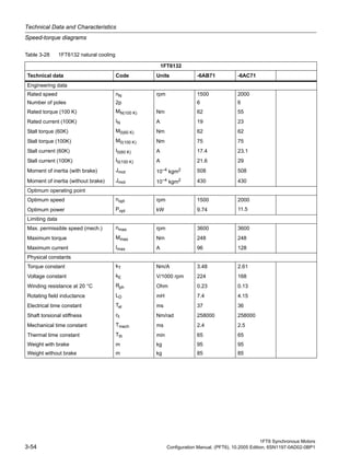
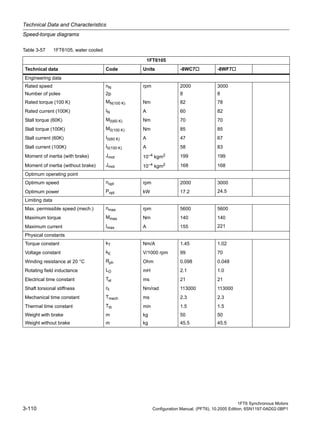
Table 3-42: 1FT6 series, force ventilated
[a] MASTERDRIVES MC, VDC link = 540 V (DC), Vmot = 340 Vrms
[b] SIMODRIVE 611 (UE), VDC link = 540 V (DC) and MASTERDRIVES MC (AFE), VDC link = 600 V (DC), Vmot = 380
Vrms
[c] SIMODRIVE 611(ER), VDC link = 600 V (DC), Vmot = 425 Vrms](https://image.slidesharecdn.com/mtr-1ft6-configuration-simodrive-masterdrive-manual-150822210403-lva1-app6891/85/Mtr-1-ft6-configuration-simodrive-masterdrive-manual-123-320.jpg)

![1FT6 Synchronous Motors
Configuration Manual, (PFT6), 10.2005 Edition, 6SN1197-0AD02-0BP1 3-83
Technical Data and Characteristics
Speed-torque diagrams
Fig. 3-69 Speed-torque diagram 1FT6134-6SB71
Fig. 3-70 Speed-torque diagram 1FT6134-6SC71
[a] MASTERDRIVES MC, VDC link = 540 V (DC), VMot = 340 Vrms
[b] SIMODRIVE 611 (UE), VDC link = 540 V (DC) and MASTERDRIVES MC (AFE), VDC link = 600 V (DC), VMot = 380
Vrms
[c] SIMODRIVE 611 (ER), VDC link = 600 V (DC), VMot = 425 Vrms](https://image.slidesharecdn.com/mtr-1ft6-configuration-simodrive-masterdrive-manual-150822210403-lva1-app6891/85/Mtr-1-ft6-configuration-simodrive-masterdrive-manual-125-320.jpg)
![1FT6 Synchronous Motors
Configuration Manual, (PFT6), 10.2005 Edition, 6SN1197-0AD02-0BP1 3-85
Technical Data and Characteristics
Speed-torque diagrams
Fig. 3-71 Speed-torque diagram 1FT6134-6SF71
[a] MASTERDRIVES MC, VDC link = 540 V (DC), VMot = 340 Vrms
[b] SIMODRIVE 611 (UE), VDC link = 540 V (DC) and MASTERDRIVES MC (AFE), VDC link = 600 V (DC), VMot = 380
Vrms
[c] SIMODRIVE 611 (ER), VDC link = 600 V (DC), VMot = 425 Vrms](https://image.slidesharecdn.com/mtr-1ft6-configuration-simodrive-masterdrive-manual-150822210403-lva1-app6891/85/Mtr-1-ft6-configuration-simodrive-masterdrive-manual-127-320.jpg)
![1FT6 Synchronous Motors
Configuration Manual, (PFT6), 10.2005 Edition, 6SN1197-0AD02-0BP1 3-87
Technical Data and Characteristics
Speed-torque diagrams
Fig. 3-72 Speed-torque diagram 1FT6136-6SB71
Fig. 3-73 Speed-torque diagram 1FT6136-6SC71
a b c
[a] MASTERDRIVES MC, VDC link = 540 V (DC), VMot = 340 Vrms
[b] SIMODRIVE 611 (UE), VDC link = 540 V (DC) and MASTERDRIVES MC (AFE), VDC link = 600 V (DC), VMot = 380
Vrms
[c] SIMODRIVE 611 (ER), VDC link = 600 V (DC), VMot = 425 Vrms](https://image.slidesharecdn.com/mtr-1ft6-configuration-simodrive-masterdrive-manual-150822210403-lva1-app6891/85/Mtr-1-ft6-configuration-simodrive-masterdrive-manual-129-320.jpg)

![1FT6 Synchronous Motors
Configuration Manual, (PFT6), 10.2005 Edition, 6SN1197-0AD02-0BP1 3-89
Technical Data and Characteristics
Speed-torque diagrams
Fig. 3-74 Speed-torque diagram 1FT6136-6SF71
[a] MASTERDRIVES MC, VDC link = 540 V (DC), VMot = 340 Vrms
[b] SIMODRIVE 611 (UE), VDC link = 540 V (DC) and MASTERDRIVES MC (AFE), VDC link = 600 V (DC), VMot = 380
Vrms
[c] SIMODRIVE 611 (ER), VDC link = 600 V (DC), VMot = 425 Vrms](https://image.slidesharecdn.com/mtr-1ft6-configuration-simodrive-masterdrive-manual-150822210403-lva1-app6891/85/Mtr-1-ft6-configuration-simodrive-masterdrive-manual-131-320.jpg)
![1FT6 Synchronous Motors
Configuration Manual, (PFT6), 10.2005 Edition, 6SN1197-0AD02-0BP1 3-91
Technical Data and Characteristics
Speed-torque diagrams
Fig. 3-75 Speed-torque diagram 1FT6163-8SB7
Fig. 3-76 Speed-torque diagram 1FT6163-8SD7
[a] MASTERDRIVES MC, VDC link = 540 V (DC), VMot = 340 Vrms
[b] MASTERDRIVES MC (AFE), VDC link = 600 V (DC), Vmot = 380 Vrms](https://image.slidesharecdn.com/mtr-1ft6-configuration-simodrive-masterdrive-manual-150822210403-lva1-app6891/85/Mtr-1-ft6-configuration-simodrive-masterdrive-manual-133-320.jpg)
![1FT6 Synchronous Motors
Configuration Manual, (PFT6), 10.2005 Edition, 6SN1197-0AD02-0BP1 3-93
Technical Data and Characteristics
Speed-torque diagrams
Fig. 3-77 Speed-torque diagram 1FT6168-8SB7
[a] MASTERDRIVES MC, VDC link = 540 V (DC), VMot = 340 Vrms
[b] MASTERDRIVES MC (AFE), VDC link = 600 V (DC), Vmot = 380 Vrms](https://image.slidesharecdn.com/mtr-1ft6-configuration-simodrive-masterdrive-manual-150822210403-lva1-app6891/85/Mtr-1-ft6-configuration-simodrive-masterdrive-manual-135-320.jpg)

![1FT6 Synchronous Motors
Configuration Manual, (PFT6), 10.2005 Edition, 6SN1197-0AD02-0BP1 3-95
Technical Data and Characteristics
Speed-torque diagrams
Fig. 3-78 Speed-torque diagram 1FT6062-6WF7
[a] MASTERDRIVES MC, VDC link = 540 V (DC), VMot = 340 Vrms
[b] SIMODRIVE 611 (UE), VDC link = 540 V (DC) and MASTERDRIVES MC (AFE), VDC link = 600 V (DC), VMot = 380
Vrms
[c] SIMODRIVE 611 (ER), VDC link = 600 V (DC), VMot = 425 Vrms](https://image.slidesharecdn.com/mtr-1ft6-configuration-simodrive-masterdrive-manual-150822210403-lva1-app6891/85/Mtr-1-ft6-configuration-simodrive-masterdrive-manual-137-320.jpg)
![1FT6 Synchronous Motors
Configuration Manual, (PFT6), 10.2005 Edition, 6SN1197-0AD02-0BP1 3-97
Technical Data and Characteristics
Speed-torque diagrams
Fig. 3-79 Speed-torque diagram 1FT6062-6WH7
Fig. 3-80 Speed-torque diagram 1FT6062-6WK7
[a] MASTERDRIVES MC, VDC link = 540 V (DC), VMot = 340 Vrms
[b] SIMODRIVE 611 (UE), VDC link = 540 V (DC) and MASTERDRIVES MC (AFE), VDC link = 600 V (DC), VMot = 380
Vrms
[c] SIMODRIVE 611 (ER), VDC link = 600 V (DC), VMot = 425 Vrms](https://image.slidesharecdn.com/mtr-1ft6-configuration-simodrive-masterdrive-manual-150822210403-lva1-app6891/85/Mtr-1-ft6-configuration-simodrive-masterdrive-manual-139-320.jpg)

![1FT6 Synchronous Motors
Configuration Manual, (PFT6), 10.2005 Edition, 6SN1197-0AD02-0BP1 3-99
Technical Data and Characteristics
Speed-torque diagrams
Fig. 3-81 Speed-torque diagram 1FT6064-6WF7
[a] MASTERDRIVES MC, VDC link = 540 V (DC), VMot = 340 Vrms
[b] SIMODRIVE 611 (UE), VDC link = 540 V (DC) and MASTERDRIVES MC (AFE), VDC link = 600 V (DC), VMot = 380
Vrms
[c] SIMODRIVE 611 (ER), VDC link = 600 V (DC), VMot = 425 Vrms](https://image.slidesharecdn.com/mtr-1ft6-configuration-simodrive-masterdrive-manual-150822210403-lva1-app6891/85/Mtr-1-ft6-configuration-simodrive-masterdrive-manual-141-320.jpg)

![1FT6 Synchronous Motors
Configuration Manual, (PFT6), 10.2005 Edition, 6SN1197-0AD02-0BP1 3-101
Technical Data and Characteristics
Speed-torque diagrams
Fig. 3-82 Speed-torque diagram 1FT6064-6WH7
Fig. 3-83 Speed-torque diagram 1FT6064-6WK7
[a] MASTERDRIVES MC, VDC link = 540 V (DC), VMot = 340 Vrms
[b] SIMODRIVE 611 (UE), VDC link = 540 V (DC) and MASTERDRIVES MC (AFE), VDC link = 600 V (DC), VMot = 380
Vrms
[c] SIMODRIVE 611 (ER), VDC link = 600 V (DC), VMot = 425 Vrms](https://image.slidesharecdn.com/mtr-1ft6-configuration-simodrive-masterdrive-manual-150822210403-lva1-app6891/85/Mtr-1-ft6-configuration-simodrive-masterdrive-manual-143-320.jpg)

![1FT6 Synchronous Motors
Configuration Manual, (PFT6), 10.2005 Edition, 6SN1197-0AD02-0BP1 3-103
Technical Data and Characteristics
Speed-torque diagrams
Fig. 3-84 Speed-torque diagram 1FT6084-8WF7
[a] MASTERDRIVES MC, VDC link = 540 V (DC), VMot = 340 Vrms
[b] SIMODRIVE 611 (UE), VDC link = 540 V (DC) and MASTERDRIVES MC (AFE), VDC link = 600 V (DC), VMot = 380
Vrms
[c] SIMODRIVE 611 (ER), VDC link = 600 V (DC), VMot = 425 Vrms](https://image.slidesharecdn.com/mtr-1ft6-configuration-simodrive-masterdrive-manual-150822210403-lva1-app6891/85/Mtr-1-ft6-configuration-simodrive-masterdrive-manual-145-320.jpg)

![1FT6 Synchronous Motors
Configuration Manual, (PFT6), 10.2005 Edition, 6SN1197-0AD02-0BP1 3-105
Technical Data and Characteristics
Speed-torque diagrams
Fig. 3-85 Speed-torque diagram 1FT6084-8WH71
Fig. 3-86 Speed-torque diagram 1FT6084-8WK71
a b c
[a] MASTERDRIVES MC, VDC link = 540 V (DC), VMot = 340 Vrms
[b] SIMODRIVE 611 (UE), VDC link = 540 V (DC) and MASTERDRIVES MC (AFE), VDC link = 600 V (DC), VMot = 380
Vrms
[c] SIMODRIVE 611 (ER), VDC link = 600 V (DC), VMot = 425 Vrms](https://image.slidesharecdn.com/mtr-1ft6-configuration-simodrive-masterdrive-manual-150822210403-lva1-app6891/85/Mtr-1-ft6-configuration-simodrive-masterdrive-manual-147-320.jpg)
![1FT6 Synchronous Motors
Configuration Manual, (PFT6), 10.2005 Edition, 6SN1197-0AD02-0BP1 3-107
Technical Data and Characteristics
Speed-torque diagrams
Fig. 3-87 Speed-torque diagram 1FT6086-8WF7
[a] MASTERDRIVES MC, VDC link = 540 V (DC), VMot = 340 Vrms
[b] SIMODRIVE 611 (UE), VDC link = 540 V (DC) and MASTERDRIVES MC (AFE), VDC link = 600 V (DC), VMot = 380
Vrms
[c] SIMODRIVE 611 (ER), VDC link = 600 V (DC), VMot = 425 Vrms](https://image.slidesharecdn.com/mtr-1ft6-configuration-simodrive-masterdrive-manual-150822210403-lva1-app6891/85/Mtr-1-ft6-configuration-simodrive-masterdrive-manual-149-320.jpg)

![1FT6 Synchronous Motors
Configuration Manual, (PFT6), 10.2005 Edition, 6SN1197-0AD02-0BP1 3-109
Technical Data and Characteristics
Speed-torque diagrams
Fig. 3-88 Speed-torque diagram 1FT6086-8WH7
Fig. 3-89 Speed-torque diagram 1FT6086-8WK7
[a] MASTERDRIVES MC, VDC link = 540 V (DC), VMot = 340 Vrms
[b] SIMODRIVE 611 (UE), VDC link = 540 V (DC) and MASTERDRIVES MC (AFE), VDC link = 600 V (DC), VMot = 380
Vrms
[c] SIMODRIVE 611 (ER), VDC link = 600 V (DC), VMot = 425 Vrms](https://image.slidesharecdn.com/mtr-1ft6-configuration-simodrive-masterdrive-manual-150822210403-lva1-app6891/85/Mtr-1-ft6-configuration-simodrive-masterdrive-manual-151-320.jpg)
![1FT6 Synchronous Motors
Configuration Manual, (PFT6), 10.2005 Edition, 6SN1197-0AD02-0BP1 3-111
Technical Data and Characteristics
Speed-torque diagrams
Fig. 3-90 Speed-torque diagram 1FT6105-8WC7
Fig. 3-91 Speed-torque diagram 1FT6105-8WF7
[a] MASTERDRIVES MC, VDC link = 540 V (DC), VMot = 340 Vrms
[b] SIMODRIVE 611 (UE), VDC link = 540 V (DC) and MASTERDRIVES MC (AFE), VDC link = 600 V (DC), VMot = 380
Vrms
[c] SIMODRIVE 611 (ER), VDC link = 600 V (DC), VMot = 425 Vrms](https://image.slidesharecdn.com/mtr-1ft6-configuration-simodrive-masterdrive-manual-150822210403-lva1-app6891/85/Mtr-1-ft6-configuration-simodrive-masterdrive-manual-153-320.jpg)

![1FT6 Synchronous Motors
Configuration Manual, (PFT6), 10.2005 Edition, 6SN1197-0AD02-0BP1 3-113
Technical Data and Characteristics
Speed-torque diagrams
Fig. 3-92 Speed-torque diagram 1FT6108-8WB7
Fig. 3-93 Speed-torque diagram 1FT6108-8WC7
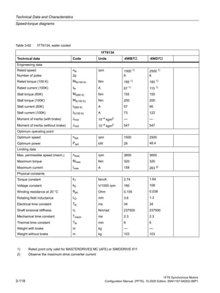
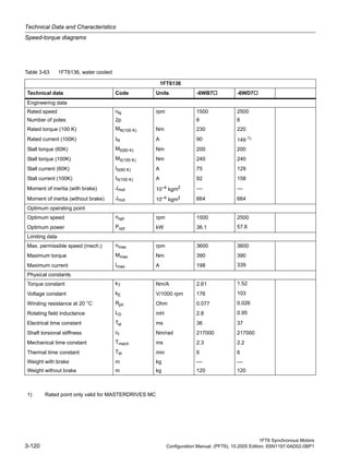
Table 3-59: 1FT6 series, water cooled
[a] MASTERDRIVES MC, VDC link = 540 V (DC), VMot = 340 Vrms
[b] SIMODRIVE 611 (UE), VDC link = 540 V (DC) and MASTERDRIVES MC (AFE), VDC link = 600 V (DC), VMot = 380
Vrms
[c] SIMODRIVE 611 (ER), VDC link = 600 V (DC), VMot = 425 Vrms](https://image.slidesharecdn.com/mtr-1ft6-configuration-simodrive-masterdrive-manual-150822210403-lva1-app6891/85/Mtr-1-ft6-configuration-simodrive-masterdrive-manual-155-320.jpg)

![1FT6 Synchronous Motors
Configuration Manual, (PFT6), 10.2005 Edition, 6SN1197-0AD02-0BP1 3-115
Technical Data and Characteristics
Speed-torque diagrams
Fig. 3-94 Speed-torque diagram 1FT6108-8WF7
[a] MASTERDRIVES MC, VDC link = 540 V (DC), VMot = 340 Vrms
[b] SIMODRIVE 611 (UE), VDC link = 540 V (DC) and MASTERDRIVES MC (AFE), VDC link = 600V (DC), Vmot = 380
Vrms
[c] SIMODRIVE 611 (ER), VDC link = 600 V (DC), VMot = 425 Vrms](https://image.slidesharecdn.com/mtr-1ft6-configuration-simodrive-masterdrive-manual-150822210403-lva1-app6891/85/Mtr-1-ft6-configuration-simodrive-masterdrive-manual-157-320.jpg)

![1FT6 Synchronous Motors
Configuration Manual, (PFT6), 10.2005 Edition, 6SN1197-0AD02-0BP1 3-117
Technical Data and Characteristics
Speed-torque diagrams
Fig. 3-95 Speed-torque diagram 1FT6132-6WB7
Fig. 3-96 Speed-torque diagram 1FT6132-6WD7
[a] MASTERDRIVES MC, VDC link = 540 V (DC), VMot = 340 Vrms
[b] SIMODRIVE 611 (UE), VDC link = 540 V (DC) and MASTERDRIVES MC (AFE), VDC link = 600V (DC), Vmot = 380
Vrms
[c] SIMODRIVE 611 (ER), VDC link = 600 V (DC), VMot = 425 Vrms](https://image.slidesharecdn.com/mtr-1ft6-configuration-simodrive-masterdrive-manual-150822210403-lva1-app6891/85/Mtr-1-ft6-configuration-simodrive-masterdrive-manual-159-320.jpg)
![1FT6 Synchronous Motors
Configuration Manual, (PFT6), 10.2005 Edition, 6SN1197-0AD02-0BP1 3-119
Technical Data and Characteristics
Speed-torque diagrams
Fig. 3-97 Speed-torque diagram 1FT6134-6WB7
Fig. 3-98 Speed-torque diagram 1FT6134-6WD7
[a] MASTERDRIVES MC, VDC link = 540 V (DC), VMot = 340 Vrms
[b] SIMODRIVE 611 (UE), VDC link = 540 V (DC) and MASTERDRIVES MC (AFE), VDC link = 600V (DC), Vmot = 380
Vrms
[c] SIMODRIVE 611 (ER), VDC link = 600 V (DC), VMot = 425 Vrms](https://image.slidesharecdn.com/mtr-1ft6-configuration-simodrive-masterdrive-manual-150822210403-lva1-app6891/85/Mtr-1-ft6-configuration-simodrive-masterdrive-manual-161-320.jpg)
![1FT6 Synchronous Motors
Configuration Manual, (PFT6), 10.2005 Edition, 6SN1197-0AD02-0BP1 3-121
Technical Data and Characteristics
Speed-torque diagrams
Fig. 3-99 Speed-torque diagram 1FT6136-6WB7
Fig. 3-100 Speed-torque diagram 1FT6136-6WD7
[a] MASTERDRIVES MC, VDC link = 540 V (DC), VMot = 340 Vrms
[b] SIMODRIVE 611 (UE), VDC link = 540 V (DC) and MASTERDRIVES MC (AFE), VDC link = 600V (DC), Vmot = 380
Vrms
[c] SIMODRIVE 611 (ER), VDC link = 600 V (DC), VMot = 425 Vrms](https://image.slidesharecdn.com/mtr-1ft6-configuration-simodrive-masterdrive-manual-150822210403-lva1-app6891/85/Mtr-1-ft6-configuration-simodrive-masterdrive-manual-163-320.jpg)
![1FT6 Synchronous Motors
Configuration Manual, (PFT6), 10.2005 Edition, 6SN1197-0AD02-0BP1 3-123
Technical Data and Characteristics
Speed-torque diagrams
Fig. 3-101 Speed-torque diagram 1FT6138-6WB7
Fig. 3-102 Speed-torque diagram 1FT6138-6WD7
[a] MASTERDRIVES MC, VDC link = 540 V (DC), VMot = 340 Vrms
[b] MASTERDRIVES MC (AFE), VDC link = 600 V (DC), Vmot = 380 Vrms
[c] SIMODRIVE 611 (ER), VDC link = 600 V (DC), VMot = 425 Vrms](https://image.slidesharecdn.com/mtr-1ft6-configuration-simodrive-masterdrive-manual-150822210403-lva1-app6891/85/Mtr-1-ft6-configuration-simodrive-masterdrive-manual-165-320.jpg)
![1FT6 Synchronous Motors
Configuration Manual, (PFT6), 10.2005 Edition, 6SN1197-0AD02-0BP1 3-125
Technical Data and Characteristics
Speed-torque diagrams
Fig. 3-103 Speed-torque diagram 1FT6163-8WB7
Fig. 3-104 Speed-torque diagram 1FT6163-8WD7
[a] MASTERDRIVES MC, VDC link = 540 V (DC), VMot = 340 Vrms
[b] MASTERDRIVES MC (AFE), VDC link = 600 V (DC), Vmot = 380 Vrms](https://image.slidesharecdn.com/mtr-1ft6-configuration-simodrive-masterdrive-manual-150822210403-lva1-app6891/85/Mtr-1-ft6-configuration-simodrive-masterdrive-manual-167-320.jpg)

![1FT6 Synchronous Motors
Configuration Manual, (PFT6), 10.2005 Edition, 6SN1197-0AD02-0BP1 3-127
Technical Data and Characteristics
Speed-torque diagrams
Fig. 3-105 Speed-torque diagram 1FT6168-8WB7
1FT6168-8WB7
0
200
400
600
800
1000
1200
1400
0 200 400 600 800 1000 1200 1400 1600 1800 2000
n [rpm]
M[Nm]
S1 (100K)
S1 (60K)
S3 - 40%
100K
S3 - 25%
S3 - 60 %
a b
[a] MASTERDRIVES MC, VDC link = 540 V (DC), VMot = 340 Vrms
[b] MASTERDRIVES MC (AFE), VDC link = 600 V (DC), Vmot = 380 Vrms](https://image.slidesharecdn.com/mtr-1ft6-configuration-simodrive-masterdrive-manual-150822210403-lva1-app6891/85/Mtr-1-ft6-configuration-simodrive-masterdrive-manual-169-320.jpg)
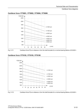
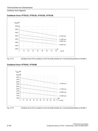
![Technical Data and Characteristics
Cantilever force diagrams
1FT6 Synchronous Motors
3-128 Configuration Manual, (PFT6), 10.2005 Edition, 6SN1197-0AD02-0BP1
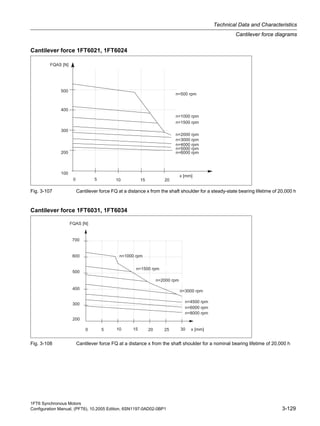
3.2 Cantilever force diagrams
Cantilever force stressing
Point of application of cantilever forces FQ at the shaft end
• for average operating speeds
• for a nominal bearing lifetime of 20,000 h
Fig. 3-106 Force application point at the drive shaft end
Dimension x: Distance between the point of application of force FQ and the shaft shoulder in
mm.
Dimension l: Length of the shaft end in mm.
Calculating the belt pre-tension force FR
When using other configurations, the actual forces generated from the torque being trans-
ferred must be taken into account.
FR [N] = 2 • M0 • c / dR FR = FQper
Table 3-67 Explanation of the formula abbreviations
Formula abbreviations Units Description
FR N Belt pre-tension
M0 Nm Motor stall torque
c ––– Pre-tensioning factor; the pre-tensioning factor is an
empirical value from the belt manufacturer.
It can be assumed as follows:
for toothed belts: c = 1.5 to 2.2
for flat belts c = 2.2 to 3.0
dR m Effective diameter of the belt pulley](https://image.slidesharecdn.com/mtr-1ft6-configuration-simodrive-masterdrive-manual-150822210403-lva1-app6891/85/Mtr-1-ft6-configuration-simodrive-masterdrive-manual-170-320.jpg)
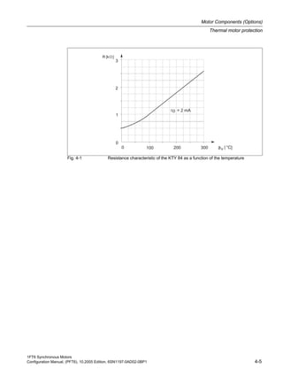
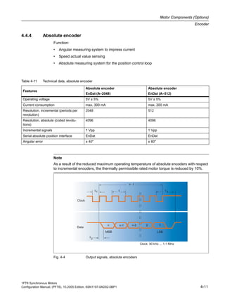
![Motor Components (Options)
Output coupling
1FT6 Synchronous Motors
4-2 Configuration Manual, (PFT6), 10.2005 Edition, 6SN1197-0AD02-0BP1
Table 4-1 Assignment of the output couplings to the motors
Shaft height of
the
1FT6 motor
dw [mm] 1) Rotex GS
Size
98 Sh A GS
TR [Nm] 4)
TKN [Nm] 2) TKmax [Nm] 3)
1FT602 9 9 5 10 2,6
1FT603 14 14 12,5 25 8,1
1FT6041 19 19 17 34 32
1FT6044 19 24 60 120 39
1FT606x–6A 24 24 60 120 43
1FT6062–6W 24 24 60 120 43
1FT6064–6W 24 28 60 120 91
1FT608x–8A 32 28 160 320 102
1FT608x–8S 32 28 160 320 102
1FT6084–8W 32 28 160 320 102
1FT6086–8W 32 38 325 650 113
1FT6102..5 38 38 325 650 122
1FT6108 38 42 450 900 ––
1FT613x–6A 48 42 450 900 ––
1FT613x–6S 48 42 450 900 ––
1FT6132..4–6W 48 48 525 1050 ––
1FT6136..8–6W 48 55 685 1370 ––
1FT6163 55 65 940 5) 1880 5) ––
1FT6168 55 75 1920 5)
3840 5) ––
1) dw = diameter, motor shaft end
2) TKN = rated coupling torque
3) TKmax = maximum coupling torque
4) TR = friction-locked torque (torque that can be transmitted using a clamping hub at dw)
5) Values for 95 Sh A GS
Warning
The accelerating torque may not exceed the friction-locked torque of the coupling!
Notice
We cannot accept any liability for the quality and properties/features of third-party products.](https://image.slidesharecdn.com/mtr-1ft6-configuration-simodrive-masterdrive-manual-150822210403-lva1-app6891/85/Mtr-1-ft6-configuration-simodrive-masterdrive-manual-178-320.jpg)
![1FT6 Synchronous Motors
Configuration Manual, (PFT6), 10.2005 Edition, 6SN1197-0AD02-0BP1 4-3
Motor Components (Options)
Holding brake (option)
4.2 Holding brake (option)
For a description of the function, refer to the Configuration Manual "General Section for Syn-
chronous Motors".
Holding torque M4
The holding torque M4 is the minimum brake torque in steady-state operation (when the motor
is at a standstill).
For motors with forced ventilation or water cooling, the brake holding torque can be less than
the motor stall torque.
Note
Motors with or without holding brake cannot be subsequently retrofitted.
Motors with holding brake are longer by the mounted space required (refer to the dimension
drawing).
Table 4-2 Technical data of the holding brakes used for 1FT6 motors
Motor type Brake type
Holding
torque
M4 1)
DC current
Opening time
with varistor
Closing time
with varistor
Highest
switching
energy
[Nm] [A] [ms] [ms] [J]
1FT602 EBD 0.11 B 1 0.3 20 10 9
1FT603 EBD 0.15 B 2 0.4 30 15 27
1FT604 EBD 0.4 BA 5 0.8 50 20 125
1FT606 EBD 1.5 B 15 0.8 130 30 320
1FT6081 EBD 1.2 B 15 0.8 150 35 750
1FT6082 EBD 1.2 B 15 0.8 150 35 750
1FT6084 EBD 3.5 BN 28 0.9 180 35 1600
1FT6086 EBD 3.5 BN 28 0.9 180 35 1600
1FT610 EBD 4 B 70 1.4 220 50 2100
1FT613 2) EBD 8 B 140 1.7 300 90 9800
1) Standardized acc. to VDE 0580 with varistor circuit
2) Not for water cooling
Caution
For several motor versions (air cooling and water cooling) the brake holding torque is less
than the rated motor torque.](https://image.slidesharecdn.com/mtr-1ft6-configuration-simodrive-masterdrive-manual-150822210403-lva1-app6891/85/Mtr-1-ft6-configuration-simodrive-masterdrive-manual-179-320.jpg)
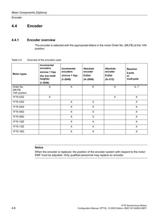

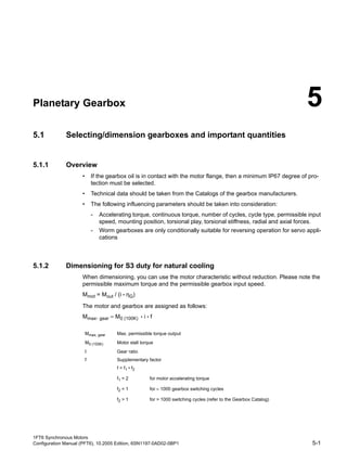
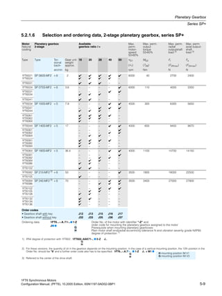
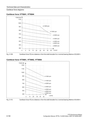
![Planetary Gearbox
Selecting/dimension gearboxes and important quantities
1FT6 Synchronous Motors
5-2 Configuration Manual, (PFT6), 10.2005 Edition, 6SN1197-0AD02-0BP1
Fig. 5-1 Dimensioning the gearbox
The load torque and the required traversing velocity define the gearbox drive-out torque, the
drive-out speed and therefore the drive-out power.
The required drive power is calculated from this:
Pout [W] = Pmot • ηG = (π/30) • Mmot [Nm] • nmot [RPM] • ηG
5.1.3 Dimensioning for S1 duty for naturally cooled systems
The gearbox itself generates heat due to friction and acts as a thermal barrier preventing heat
from being dissipated through the motor flange. This is the reason that the torque must be
reduced for S1 duty.
The required motor torque is calculated as follows:
Notice
Switching cycles can also be superimposed vibration! The supplementary factor (f2) is then
not sufficient when dimensioning the gearbox and gearboxes may fail.
The complete system should be optimized so that the higher-level vibration is minimized.
MV Calculated "torque loss"
a π/3 for 1FT6/1FK motors supplied with sinusoidal current
b 0.5 weighting factor for gearbox losses (without dimensions)
nmot Motor speed [RPM]
kT Torque constant [Nm/A]
Rph. Motor phase resistance when warm [Ω] = 1.4 Rph. (list)
Mout Gearbox drive-out torque [Nm]
i Gearbox ratio (i>1)
ηG Gearbox efficiency
Pmot Motor power [W]
Pout Gearbox drive-out power [W]
Mmot Motor torque [Nm]
( )
2
22
•1
60
•b•a=)+
•i
(=
R
kn
MMM
M
M --](https://image.slidesharecdn.com/mtr-1ft6-configuration-simodrive-masterdrive-manual-150822210403-lva1-app6891/85/Mtr-1-ft6-configuration-simodrive-masterdrive-manual-190-320.jpg)
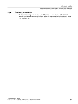
![Planetary Gearbox
Selecting/dimension gearboxes and important quantities
1FT6 Synchronous Motors
5-4 Configuration Manual, (PFT6), 10.2005 Edition, 6SN1197-0AD02-0BP1
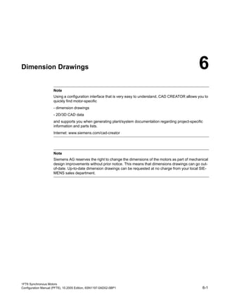
5.1.5 Rating plate data
Fig. 5-2 Rating plate data (example: 1FK7; 1FT6 is similar)
1) Motor type: AC servo motor 15) Degree of protection
2) Ident. No., production number 16) Rated speed n1N [RPM] of the motor
Gearbox drive
3) Continuous stall torque M0 [Nm] 17) Holding brake data
4) Rated torque MN [Nm] 18) Gearbox oil designation ***)
5) Temperature Class 19) Designation, quantity of gearbox oil ***)
6) Designation, encoder type 20) Geared motor weight m [kg]
7) Designation, gearbox type 21) Barcode
8) Designation, gearbox ratio;
[exact ratio]
22) Geared motor version
9) Designation, geared motor mounting position 23) Encoder version
10) Standards and regulations 24) Rated torque output, gearbox output M2N [Nm]
(duty type) *)
11) Stall current I0 [A] 25) Output speed n2 [RPM] Gearbox output **)
12) Rated motor current IN [A] 26) Max. current Imax [A]
13) Induced voltage VIN [V] 27) Order options
14) Maximum speed n1max [RPM] of the motor
(gearbox drive)
28) SIEMENS motor type/designation
*) M2N = ƒ(M1N) **)
***) Only for gearbox types SP 210 and SP 240 and
helical/angled gearboxes
n < n n =
n
i
n > n n =
n
i](https://image.slidesharecdn.com/mtr-1ft6-configuration-simodrive-masterdrive-manual-150822210403-lva1-app6891/85/Mtr-1-ft6-configuration-simodrive-masterdrive-manual-192-320.jpg)