This manual provides instructions for connecting machine tools to FANUC Series 30i-B, 31i-B5, 31i-B and 32i-B CNC systems. It describes the total connection diagrams, installation requirements, power supply connections, connections to peripheral devices and servo/spindle interfaces. The manual also covers connections to FANUC I/O Link I/O units and the handling of stop and emergency stop signals.


![B-64483EN/01 TABLE OF CONTENTS
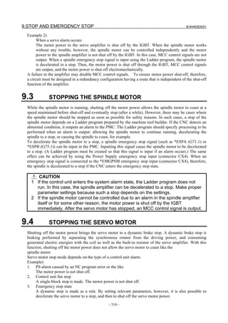
9.3 STOPPING THE SPINDLE MOTOR ......................................................... 316
9.4 STOPPING THE SERVO MOTOR ............................................................ 316
9.5 EMERGENCY STOP SIGNAL................................................................... 317
9.6 CAUTIONS ABOUT MULTI-PATH CONTROL .......................................... 320
10 CONNECTION TO OTHER NETWORKS ........................................... 321
11 CONNECTION FOR PERSONAL COMPUTER FUNCTION WITH
Windows® CE .................................................................................... 322
11.1 TOTAL CONNECTION DIAGRAMS .......................................................... 322
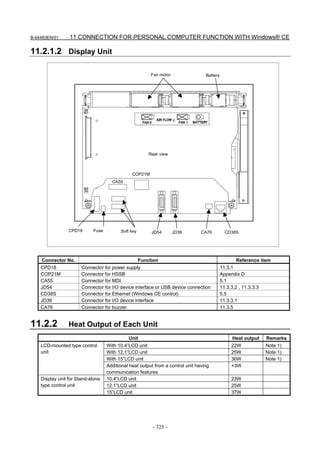
11.1.1 LCD-mounted Type Control Unit ........................................................................322
11.1.2 Display Unit (Stand-alone Type) .........................................................................323
11.2 INSTALLATION ......................................................................................... 324
11.2.1 Connector Names and Connector Layout.............................................................324
11.2.1.1 LCD-mounted type control unit....................................................................... 324
11.2.1.2 Display Unit..................................................................................................... 325
11.2.2 Heat Output of Each Unit .....................................................................................325
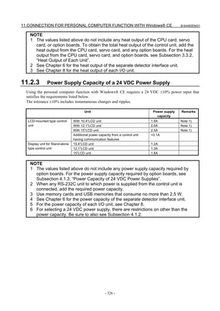
11.2.3 Power Supply Capacity of a 24 VDC Power Supply ...........................................326
11.2.4 CONNECTION TO CONTROL UNIT ...............................................................327
11.3 CONNECTION TO PERIPHERAL DEVICES ............................................ 327
11.3.1 Main Power Input.................................................................................................327
11.3.2 Ethernet (10BASE-T/ 100BASE-TX)..................................................................328
11.3.3 Serial Port and USB Port......................................................................................328
11.3.3.1 Serial port 1 ..................................................................................................... 328
11.3.3.2 Serial Port 2 ..................................................................................................... 330
11.3.3.3 USB port (rear side)......................................................................................... 332
11.3.3.4 USB port (front side) ....................................................................................... 334
11.3.4 High-speed Serial Bus (HSSB) [For Stand-alone Type] ......................................334
11.3.5 Buzzer Interface ...................................................................................................335
12 CONNECTION WITH FANUC PANEL i AND COMMERCIAL
PERSONAL COMPUTERS ................................................................. 336
12.1 OVERVIEW ............................................................................................... 336
12.2 CAUTIONS ................................................................................................ 336
12.3 CONNECTION USING THE HIGH-SPEED SERIAL BUS (HSSB)............ 336
12.3.1 Overview ..............................................................................................................336
12.3.2 Connection Diagram.............................................................................................337
12.3.3 Specifications of a Commercial PC......................................................................337
12.3.4 Installation Environment ......................................................................................338
12.3.5 Handling Precautions ...........................................................................................338
12.3.6 Procedure for Installing Personal Computer Interface Boards .............................338
12.3.7 Cable Connection .................................................................................................339
12.4 CONNECTION USING Ethernet................................................................ 340
12.4.1 Overview ..............................................................................................................340
12.4.2 Connection Diagram.............................................................................................340
13 PANEL i .......................................................................................................... 341
APPENDIX
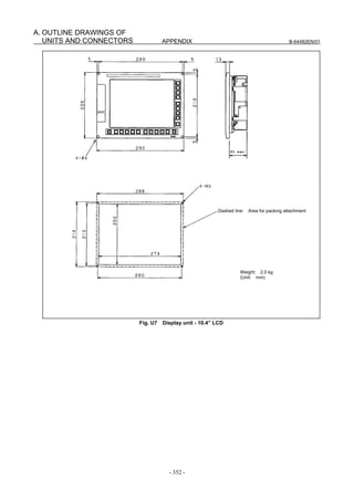
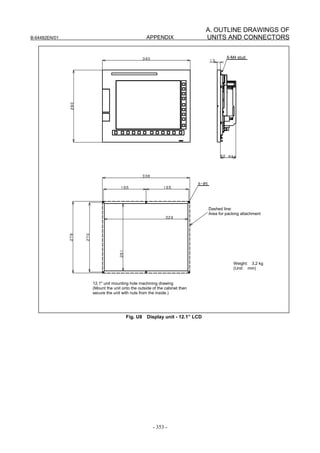
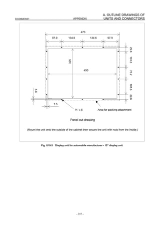
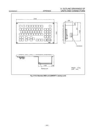
A OUTLINE DRAWINGS OF UNITS AND CONNECTORS ................... 345
B 20-PIN INTERFACE CONNECTORS AND CABLES ......................... 392
c-7](https://image.slidesharecdn.com/b-64483en01-121206192203-phpapp02/85/B-64483-en-01-19-320.jpg)

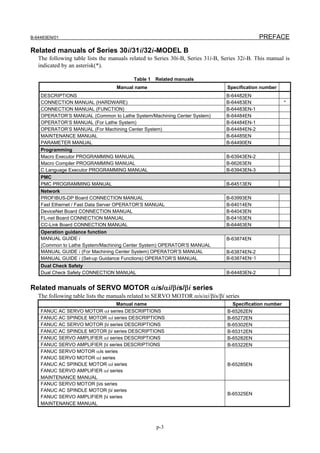
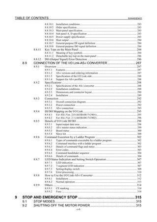
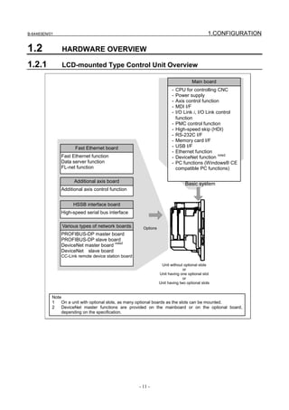
![B-64483EN/01 1.CONFIGURATION
NOTE
3 The LCD (liquid-crystal display) has been fabricated using an extreme precision
technology. However, some of their pixels may fail to light or stay constantly
lighting because of their characteristics. Please be forewarned that these
phenomena are not faults.
LCD-mounted type control unit (8.4”LCD unit and 10.4”LCD unit A) (rear view)
Battery
Fan unit
(4.4)
FSSB interface
connectors
[COP10A-1] (left)
[COP10A-2] (right)
(6)
MDI connector
[CA55] (5.1)
Power supply
connector
[CPD16A]
(4.3)
Soft key connectors
DeviceNet
Fuse
connector [TBL]
(10)
I/O device interface
connector (RS-232C)
[JD56A] (5.3)
Ethernet connector
I/O device interface (Embedded Ethernet)
connector (RS-232C) [CD38A] (5.5)
[JD36A/JD54] (5.3)
High-speed skip connector
[JA40] (5.4)
Ethernet connector
I/O Link i or I/O Link connector (Multi-function Ethernet)
[JD51A] (7.2) [CD38B] (5.5)
-3-](https://image.slidesharecdn.com/b-64483en01-121206192203-phpapp02/85/B-64483-en-01-23-320.jpg)
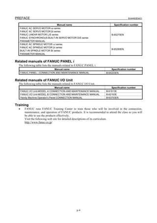
![1.CONFIGURATION B-64483EN/01
NOTE
1 This figure shows an LCD-mounted control unit having no option slot as viewed
from the rear. For the rear view of the control units having the personal computer
function with Windows® CE, see Chapter 11, "Connection for Personal
Computer Function with Windows® CE".
2 The numbers in parentheses () in the figures are keyed to the item numbers of
the descriptions in this manual. The numbers in brackets [] in the figures are
connector numbers.
3 Connectors [COP10A-2], [TBL], [CD38A], and [CD38B] may not be provided,
depending on the specifications of the hardware.
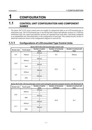
LCD-mounted type control unit (10.4”LCD unit B and 15”LCD unit) (rear view)
Battery
Fan unit
(4.4)
FSSB interface
connectors
[COP10A-1] (left)
[COP10A-2] (right)
(6)
MDI connector
[CA55] (5.1)
Fuse
Power supply
connector
[CPD16A]
(4.3)
Soft key connectors
I/O device interface
connector (RS-232C)
[JD56A] (5.3)
Ethernet connector
I/O device interface (Embedded Ethernet)
connector (RS-232C) [CD38S] (5.5)
[JD36A/JD54] (5.3)
High-speed skip connector
[JA40] (5.4)
Ethernet connector
I/O Link i or I/O Link connector (Multi-function Ethernet)
[JD51A] (7.2) [CD38B] (5.5)
-4-](https://image.slidesharecdn.com/b-64483en01-121206192203-phpapp02/85/B-64483-en-01-24-320.jpg)
![B-64483EN/01 1.CONFIGURATION
NOTE
1 This figure shows an LCD-mounted control unit having no option slot as viewed
from the rear. For the rear view of the control units having the personal computer
function with Windows® CE, see Chapter 11, "Connection for Personal
Computer Function with Windows® CE".
2 The numbers in parentheses () in the figures are keyed to the item numbers of
the descriptions in this manual. The numbers in brackets [] in the figures are
connector numbers.
3 Connectors [COP10A-2], [CD38S], and [CD38B] may not be provided,
depending on the specifications of the hardware.
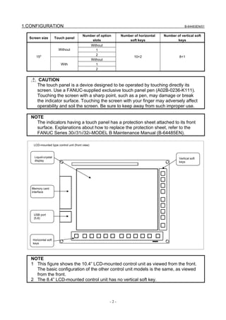
1.1.2 Configurations of Stand-alone Type Control Units
Series 30i/31i/32i stand-alone type control units
Slot rack name Number of option slots
2-slot rack 2
4-slot rack 4
Series 30i/31i/32i display units
Screen size Touch panel Number of horizontal soft keys Number of vertical soft keys
Without
10.4"
With
10+2 8+1
Without
15"
With
Series 30i/31i/32i display units having the personal computer function with Windows® CE
Screen size Touch panel Number of horizontal soft keys Number of vertical soft keys
Without
10.4"
With
Without
12.1” 10+2 8+1
With
Without
15"
With
Series 30i/31i/32i display units directed to automakers
Screen size Touch panel Number of vertical soft keys
Without
15" 16(left: 8, rights: 8)
With
CAUTION
The touch panel is a device designed to be operated by touching directly its
screen. Use a FANUC-supplied exclusive touch panel pen (A02B-0236-K111).
Touching the screen with a sharp point, such as a pen, may damage or break
the indicator surface. Touching the screen with your finger may adversely affect
operability and soil the screen. Be sure to keep away from such improper use.
-5-](https://image.slidesharecdn.com/b-64483en01-121206192203-phpapp02/85/B-64483-en-01-25-320.jpg)
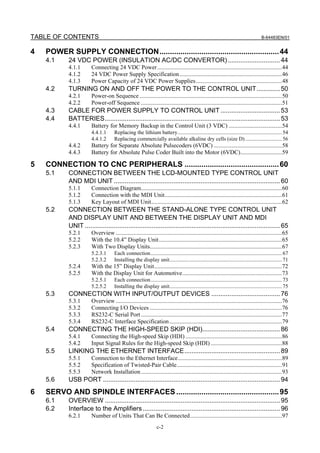
![1.CONFIGURATION B-64483EN/01
NOTE
The indicators having a touch panel has a protection sheet attached to its front
surface. Explanations about how to replace the protection sheet, refer to the
FANUC Series 30i/31i/32i-MODEL B Maintenance Manual (B-64485EN).
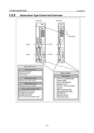
Stand-alone type control unit (front view)
Battery (4.4) Battery connector
(4.4)
I/O device interface
I/O device interface connector (RS-232C)
connector (RS-232C) [JD36A] (5.3)
[JD56A] (5.3)
I/O Link i or I/O Link
Memory card interface connector
[JD51A] (5.4)
High-speed skip connector
[JD40A] (6.1)
Ethernet connector
(Embedded Ethernet)
[CD38A] (5.5)
24-VDC power supply
Optional slot 3 connector
[CPD19A] (right)
[CPD19B] (left)
(4.3)
Optional slot 1 HSSB interface connectors
[COP21A] (5.2)
FSSB interface
connectors
[COP10A-1] (lower)
[COP10A-2] (upper)
(7)
Optional slot 4
Optional slot 2
GND connection terminal
2-slot rack
4-slot rack
NOTE
The numbers in parentheses () in the figures are keyed to the item numbers of
the descriptions in this manual. The numbers in brackets [] in the figures are
connector numbers.
-6-](https://image.slidesharecdn.com/b-64483en01-121206192203-phpapp02/85/B-64483-en-01-26-320.jpg)
![B-64483EN/01 1.CONFIGURATION
Display unit for the stand-alone type control unit (10.4”LCD unit A)
Liquid-crystal Vertical soft
display keys
Memory card
interface
Front view
USB port
(5.6)
Horizontal soft
keys
Rear view
MDI interconnection
connector [JA73]
(5.2)
MDI connector
[CA55] (5.2)
Soft key
connectors
Fuse
Video signal Power supply
interconnection connector connectors
[CP1A]
[CA103] (5.2) [CP1B] (5.2)
Optical connector for
Touch panel connector display control
[COP21B] (5.2)
NOTE
1 The numbers in parentheses () in the figures are keyed to the item numbers of
the descriptions in this manual. The numbers in brackets [] in the figures are
connector numbers.
2 Connectors [JA73] and [CA103], the memory card interface, and USB ports may
3 See Chapter 11 for explanations about the display unit for the control unit having
the personal computer function with Windows® CE.
4 The LCD (liquid-crystal display) has been fabricated using an extreme precision
technology. However, some of their pixels may fail to light or stay constantly
lighting because of their characteristics. Please be forewarned that these
phenomena are not faults.
-7-](https://image.slidesharecdn.com/b-64483en01-121206192203-phpapp02/85/B-64483-en-01-27-320.jpg)
![1.CONFIGURATION B-64483EN/01
Display unit for the stand-alone type control unit (15”LCD unit and 10.4”LCD unit B)
Vertical soft
keys
Liquid-crystal
display
Memory card Front
interface
USB port
(5.6)
Horizontal soft
keys
MDI connector
[CA55] (5.2)
Rear
Power supply
connectors
[CPD18] (5.2)
Optical connector for
Soft key
connectors display control
Fuse [COP21M] (5.2)
NOTE
1 The numbers in parentheses () in the figures are keyed to the item numbers of
the descriptions in this manual. The numbers in brackets [] in the figures are
connector numbers.
2 For the display units for the control units having the personal computer function
with Windows® CE, see Chapter 11, "Connection for Personal Computer
Function with Windows® CE".
3 The LCD (liquid-crystal display) has been fabricated using an extreme precision
technology. However, some of their pixels may fail to light or stay constantly
lighting because of their characteristics. Please be forewarned that these
phenomena are not faults.
-8-](https://image.slidesharecdn.com/b-64483en01-121206192203-phpapp02/85/B-64483-en-01-28-320.jpg)
![B-64483EN/01 1.CONFIGURATION
Display unit for automotive for the stand-alone type control unit
Vertical soft
keys
Liquid-crystal
display
MDI
Memory card Front
interface
USB port
(5.2)
Function key
switches Optical connector for
display control
[COP21M] (5.2)
Power supply
connector
[CPD18] (5.2)
Rear
I/O Link i or I/O Link connector
(master side) (5.2)
I/O Link i or I/O Link
connector (slave side) I/O Link adapter board
(5.2)
NOTE
1 The numbers in parentheses () in the figures are keyed to the item numbers of
the descriptions in this manual. The numbers in brackets [] in the figures are
connector numbers.
2 The I/O Link i and I/O Link interfaces are optional.
3 The LCD (liquid-crystal display) has been fabricated using an extreme precision
technology. However, some of their pixels may fail to light or stay constantly
lighting because of their characteristics. Please be forewarned that these
phenomena are not faults.
-9-](https://image.slidesharecdn.com/b-64483en01-121206192203-phpapp02/85/B-64483-en-01-29-320.jpg)
![1.CONFIGURATION B-64483EN/01
1.1.3 Configurations of Optional Boards
Additional axis board PROFIBUS-DP slave board
For FSSB interface For Profibus
[COP10A] (6) [CN2] (10)
Fast Ethernet board DeviceNet master board
For Ethernet For Device NET
[CD38R] (10) [TBL] (10)
HSSB interface board DeviceNet slave board
For HSSB interface For Device NET
[COP21A] (12.3) [TBL] (10)
PROFIBUS-DP master board CC-Link remote device station board
For Profibus For CC-Link
[CN1] (10) [CT1] (10)
NOTE
The numbers in parentheses () in the figures are keyed to the item numbers of
the descriptions in this manual. The numbers in brackets [] in the figures are
connector numbers.
The Fast Ethernet board may be used also as data server or FL-net functions,
depending on the settings of parameters.
- 10 -](https://image.slidesharecdn.com/b-64483en01-121206192203-phpapp02/85/B-64483-en-01-30-320.jpg)


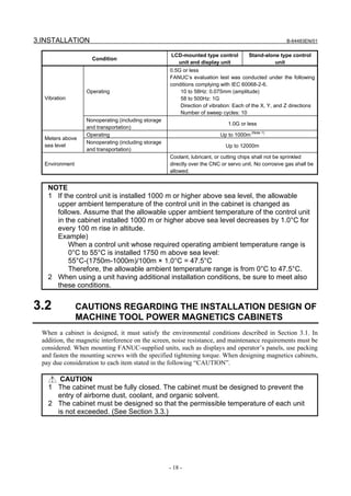

![3.INSTALLATION B-64483EN/01
3.3 THERMAL DESIGN OF THE MACHINE TOOL MAGNETIC
CABINET
The internal air temperature of the cabinet increases when the units and parts installed in the cabinet
generate heat. Since the generated heat is radiated from the surface of the cabinet, the temperature of the
air in the cabinet and the outside air balance at certain heat levels. If the amount of heat generated is
constant, the larger the surface area of the cabinet, the less the internal temperature rises. The thermal
design of the cabinet refers to calculating the heat generated in the cabinet, evaluating the surface area of
the cabinet, and enlarging that surface area by installing heat exchangers in the cabinet, if necessary.
Such a design method is described in the following subsections.
3.3.1 Temperature Rise within the Machine Tool Magnetic Cabinet
The cooling capacity of a cabinet made of sheet metal is generally 6 W/°C per 1m2 surface area, that is,
when the 6W heat source is contained in a cabinet having a surface area of 1 m2, the temperature of the air
in the cabinet rises by 1°C. In this case the surface area of the cabinet refers to the area useful in cooling,
that is, the area obtained by subtracting the area of the cabinet touching the floor from the total surface
area of the cabinet. There are two preconditions : The air in the cabinet must be circuited by the fun, and
the temperature of the air in the cabinet must be almost constant. For example, the operator’s panel
cabinet may contain an LCD-mounted type control unit or the display of a stand-alone type control unit.
To keep the temperature in the cabinet at 58°C or below when the ambient temperature is 45°C, the
equation below must be satisfied.
Internal heat loss P [W] ≤
6[W/m2⋅°C] × surface area S[m2] × 13[°C] of rise in temperature
(A cooling capacity of 6 W/°C assumes the cabinet is so large that agitation with the fan motor does not
make the temperature distribution uniform. For a small cabinet like the operator's panel, a cooling
capacity of 8 W/°C, indicated in Subsection 3.3.3, may be used.)
For example, a cabinet having a surface area of 4m2 has a cooling capacity of 24W/°C. To limit the
internal temperature increase to 13°C under these conditions, the internal heat must not exceed 312W. If
the actual internal heat is 360W, however, the temperature in the cabinet rises by 15°C. When this
happens, the cooling capacity of the cabinet must be improved using the heat exchanger.
For the power magnetic cabinet containing a stand-alone type control unit, the internal temperature rise
must be suppressed to 55°C or less, instead of 58°C.
3.3.2 Heat Output of Each Unit
Table 3.3.2 Heat output
Unit Heat output Remarks
LCD-mounted type With 8.4”LCD unit 17W Note 1)
control unit With 10.4”LCD unit A 18W Note 1)
With 10.4”LCD unit B 22W Note 1)
With 15”LCD unit 36W Note 1)
Additional heat output from a control unit having +3W
communication features
Stand-alone type control unit 15W Note 1)
CPU card Standard version, dedicated to the 32i 6W
High-speed version 11W
Servo card A11, A12, A13 4W
A24, A26 6W
DeviceNet card 3.5W
- 20 -](https://image.slidesharecdn.com/b-64483en01-121206192203-phpapp02/85/B-64483-en-01-40-320.jpg)


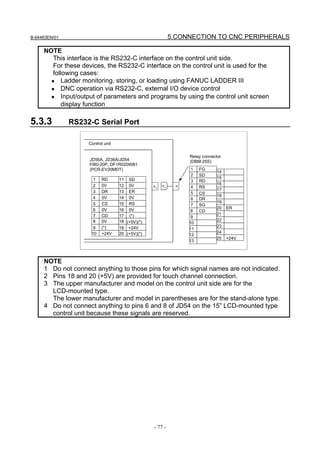


![5.CONNECTION TO CNC PERIPHERALS B-64483EN/01
NOTE
1 When the external device is equipped with an ISO/EIA converter, the following
items must be noted in Table 5.3.4.
Control out (Comment field start)
Control in (Comment field end)
EIA code (....................)) CR o .. ..................
Condition 1 Condition 1 Condition 2 Condition 3
ISO code (.....................) LF : ....................
Condition1 Left parenthesis "("of the ISO code punches holes at bits 2, 4 and 5
when used in the EIA code.
Right parenthesis ")"of the ISO code punches holes at bits 2, 4 and
7 when used in the EIA code.
Condition2 EIA code CR is LF in ISO code.
Condition3 EIA code O is : in ISO code.
2 Control codes DC1 to DC4 are transmission codes output from the control unit.
So they need not to be punched on the control unit tape.
(3) Transmission rate (Baud rate)
The transmission rate (Baud rate) is the number of bits transferred per second.
The following baud rates are available depending on the system parameter.
50, 100, 110, 150, 200, 300, 600, 1200, 2400, 4800, 9600
[Example] Baud rate : 110
When using one start bit and two stop bits (totaling 11 bits per character):
Transmission characters/second= 110/11 =10 characters/second (Max.)
(4) Cable length
The cable length depends on the external device type. Consult with the device manufacturers for
actual connecting cable lengths.
Cable length is as follows by the specification of control unit.
RS232-C Baud rate 4800 or less: Up to 100 m
Baud rate 9600 or less: Up to 50 m
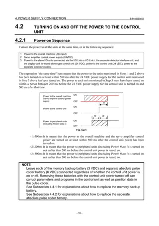
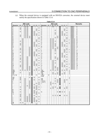
Time chart when the control unit receives data (Read into memory)
(1) Control unit outputs DC1.
(2) The I/O device starts sending data upon receiving DC1.
(3) Control unit sends DC3 when control unit processing is delayed.
(4) The I/O device stops sending data to control unit after receiving DC3.
The device may send up to 10 characters after receiving DC3. If it sends more than 10 characters,
alarm 087 will occur.
(5) Control unit reissues DC1 upon completing delayed processing.
(6) The I/O device restarts data output upon receiving the DC1 code (the data must be the next data to
the preceding.)
(7) Control unit sends DC3 upon completing data read.
(8) The I/O device stops sending data.
- 82 -](https://image.slidesharecdn.com/b-64483en01-121206192203-phpapp02/85/B-64483-en-01-102-320.jpg)


![B-64483EN/01 5.CONNECTION TO CNC PERIPHERALS
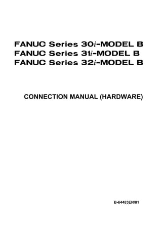
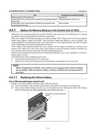
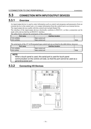
5.5.3 Network Installation
Even when the machine satisfies its grounding requirements, noise from the machine may get on
communication lines depending on the way the machine is installed and its environment, resulting in a
communication error. Separating and isolating the Ethernet backbone cable and PC from the machine can
prevent noise from getting on the communication lines.
An example of connection is shown below.
[Example of connection]
Note 1 Power supply
HUB for the HUB
PC and backbone cable side
Electrical separation by STP cable
STP cable
connection with
10BASE-T/100BASE-TX
Machine system side
Machine Machine Machine
Note 1 Note 1 Note 1
NOTE
1 Ground the PC and backbone cable separately from the machine system.
If this is impossible because there is only one grounding point, use separate
grounding wires for the PC/backbone cable and the machine system up to the
grounding point.
The grounding resistance must not be higher than 100 Ω (class 3 grounding).
The grounding wire must not be thinner than the AC power line conductor, and
its cross-sectional area must not smaller than 5.5 mm2.
2 In some cases, the aforementioned isolation/separation method based on
10BASE-T/ 100BASE-TX cannot assure normal communication because of
influence by noise. In such worst environments, use optical fiber media to
completely isolate the machine from the PC.
- 93 -](https://image.slidesharecdn.com/b-64483en01-121206192203-phpapp02/85/B-64483-en-01-113-320.jpg)


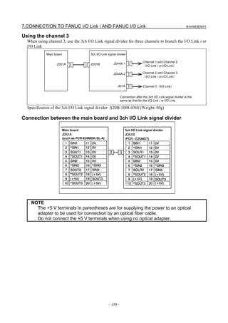
![B-64483EN/01 7.CONNECTION TO FANUC I/O Link i AND FANUC I/O Link
The FS30i-B series has a total of three channels of I/O Link i and I/O Link interfaces. When only the I/O
Link i is used, up to two channels can be used. When only the I/O Link is used, up to three channels can
be used.
Number of channels available for the I/O Link i and I/O Link
Item I/O Link I/O Link i
Number of available channels Up to 3 Up to 2
* The I/O Link i and I/O Link can be used simultaneously by selecting the I/O Link i and I/O Link for
each channel. For details, see Section 7.2, “Connection”, below.
7.2 CONNECTION
With the FS30i-B series, interface connector for the I/O Link i and I/O Link JD51A (for three channels) is
located on the main board. For channels 1 and 2 of these three channels, the I/O Link i or I/O Link can be
selected. Channel 3 is available only for the I/O Link. Each of channels 1 and 2 is used for the I/O Link i
or I/O Link according to the parameter setting. According to the initial setting, channels 1 and 2 are used
for the I/O Link. For the parameter setting, refer to the FANUC Series 30i/31i/32i-MODEL B PMC
Programming Manual (B-64513EN).
In I/O control, there are the master station and its slave stations. The master is the control unit, and the
slaves are other I/O units. The slaves are divided into groups. Up to 24 slave groups can be connected to
one channel with the I/O Link i. Up to 16 slave groups can be connected with the I/O Link.
The I/O Link i and I/O Link are connected in different ways depending on the types of units actually used
and the number of I/O signals. Therefore, the assignment and addresses of the I/O signals have been made
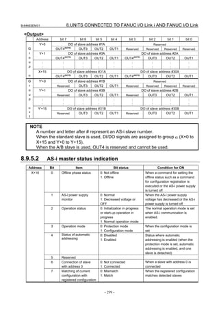
programmable with the PMC program. The maximum number of I/O signals available for each channel is
2048/2048 for the I/O Link i and 1024/1024 for the I/O Link.
Up to 4096/4096 signals in total can be used for the entire system. Within this range of the total number
of signals, the I/O Link i or I/O Link can be selected for each channel.
[Sample available combination]
Channel 1 Channel 2 Channel 3 Total number of signals (DI / DO)
I/O Link i I/O Link i ― 4096 / 4096
I/O Link i I/O Link ― 3072 / 3072
I/O Link i I/O Link I/O Link 4096 / 4096
I/O Link I/O Link I/O Link 3072 / 3072
NOTE
1 The total number of I/O signals that can be used differs depending on the model.
2 All units connected to the channel used for the I/O Link i must support the I/O
Link i.
Do not connect any unit dedicated to the I/O Link i to the channel used for the
I/O Link.
An I/O unit has I/O Link i and I/O Link interface connectors JD1A and JD1B. All units with the I/O Link
i or I/O Link function have these connectors. A cable must always be connected from JD1A to JD1B.
Although connector JD1A on the last unit is not used and left open, it is not necessary to connect JD1A
with a terminator.
The pin assignments of connectors JD1A and JD1B are common to all units with the I/O Link i or I/O
Link function. They are described in Subsection 7.2.1. Fig. 7.2 shows a connection diagram of the I/O
Link i or I/O Link.
- 121 -](https://image.slidesharecdn.com/b-64483en01-121206192203-phpapp02/85/B-64483-en-01-141-320.jpg)


![7.CONNECTION TO FANUC I/O Link i AND FANUC I/O Link B-64483EN/01
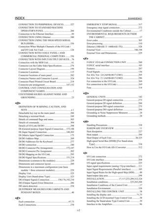
7.2.2 Connection of FANUC I/O Link i or I/O Link by Optical Fiber
Cable
The I/O Link i and I/O Link can be extended to a maximum length of 200 m with optical fiber cables
using an optical adapter. The length of the electric cable connected to the optical adapter must not exceed
2 m (when the recommended wire material is used).
Connection
Connecting cable Optical Connecting cable Connecting cable Optical Connecting cable
between units fiber cable between units between units fiber cable between units
Unit Unit Unit
Optical adapter Optical adapter Optical adapter Optical adapter
JD51A/JD1A JD1 COPx COPx JD1 JD1B JD1A JD1 COPx COPx JD1 JD1B JD1A
Optical fiber cable connection: One stage
Optical fiber cable connection: Two stages
Connecting cable between units
Unit side Optical adapter side
,JD51A
[]
[] []
[] []
[]
[]
[]
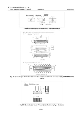
Recommended wire material A66L-0001-0284#10P (#28AWG × 10 pairs)
Recommended cable connectors PCR-E20FA (Honda Tsushin Kogyo Co., Ltd.)
FCN-247J020-G/E (FUJITSU COMPONENT)
52622-2011 (Molex Japan Co., Ltd.)
NOTE
1 The length of the cable for connecting units must not exceed 2 m (when the
recommended wire material is used).
2 Do not connect the pins in brackets. They are used for connecting channels 2
and 3 with JD51A.
3 Do not connect any pin for which no signal is assigned.
- 124 -](https://image.slidesharecdn.com/b-64483en01-121206192203-phpapp02/85/B-64483-en-01-144-320.jpg)


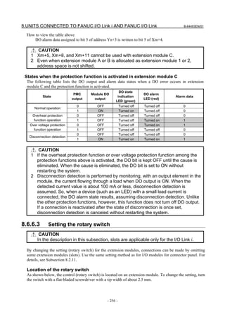
![7.CONNECTION TO FANUC I/O Link i AND FANUC I/O Link B-64483EN/01
7.3.3 Status Alarm
Some I/O units have a function which detects unit errors including DO alarms (DO ground faults) and DO
common voltage errors. If these units detect an error described above, how detected information is
transferred to the master differs between the I/O Link and I/O Link i.
With the I/O Link, detected information is transferred to the master as DI signals. For this reason, to allow
the master to reference the detected information, as many signals as required for the detected information
must be assigned to X addresses. As many signals as required for the detected information are assumed as
the number of DI signals used by the group and channel.
With the I/O Link i, detected information is called a status alarm, and the CNC is notified of the status
alarm separate from DI signals. For this reason, it is not necessary to assign the information to X
addresses. If an error occurs, the information is output to the system relay (R or Z) area. The information
only for one group per channel is output to the system relay area. Only the information for the first group
in which a status alarm is detected is output.
For details of status alarms actually detected by units, see the section for each unit in Chapter 8.
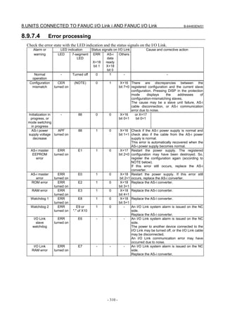
The following figure shows an example of a system relay area to which to output a status alarm. For
details of the system relay area, refer to the FANUC Series 30i/31i/32i-MODEL B PMC Programming
Manual (B-64513EN).
[Reference] System relay area related to a status alarm
Channel 1 Channel 2 7 6 5 4 3 2 1 0
R9268(Z268) R9276(Z276) Status Type
R9269(Z269) R9277(Z277) Group number
R9270(Z270) R9278(Z278) Slot number
R9271(Z271) R9279(Z279) Alarm information number
R9272(Z272) R9280(Z280)
Y address number
R9273(Z273) R9281(Z281)
R9274(Z274) R9282(Z282) PMC path
R9275(Z275) R9283(Z283) Alarm data
[Reference] Simple description of signals
Name Description
Status Indicates that a status alarm occurs when this signal is set to 1.
Type Indicates the type of status alarm.
0: DO alarm (such as a ground fault), 1: Other than a DO alarm (such as a DO
common voltage error)
Group number Outputs a group number (0 to 23).
Slot number Outputs a numeric value 0 to 31, which indicates slot number 1 to 32.
Alarm information number Outputs the position of the alarm information corresponding to the alarm which
occurs (byte position in the slot).
Y address number Outputs the Y address number of the relevant DO signal. Valid when the PMC
path value is other than 0.
PMC path Outputs the PMC path at the Y address assigned to the relevant DO signal.
Outputs 0 if no address is assigned to the DO signal.
Alarm data Outputs information on the alarm which occurs. Outputs 1 to the bit corresponding
to the alarm which occurs.
- 138 -](https://image.slidesharecdn.com/b-64483en01-121206192203-phpapp02/85/B-64483-en-01-158-320.jpg)

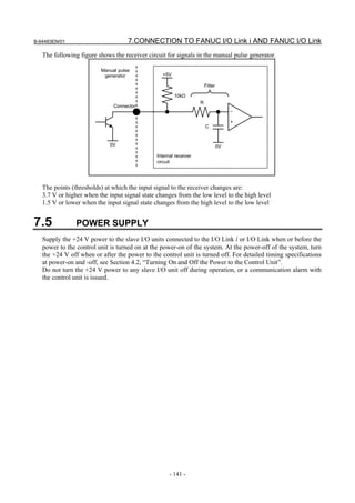
![7.CONNECTION TO FANUC I/O Link i AND FANUC I/O Link B-64483EN/01
NOTE
The number of connectable manual pulse generators depends on the type and
option configuration.
7.4.2 Cable Length for Manual Pulse Generator
The manual pulse generator operates on 5 VDC. The supply voltage drop due to the cable resistance must
be held below 0.2 V (when those of the 0-volt and 5-volt wires are combined), as expressed in the
following expression:
where
0.2≥ 0.1×R×2L 0.1 = manual pulse generator supply current (0.1 A)
m R = resistance per unit cable length (Ω/m)
m = number of 0-volt and 5-volt wires
L = cable length (m).
Therefore, the cable length can be determined using the following expression.
m
L≤
R
As an example, obtain the cable length when recommended cable wire A66L-0001-0286 is used.
This cable wire has three paired signal wires and six power connection wires. Since the electric resistance
of a power connection wire is 0.0394 Ω/m, if three wires are used for 0 V and 5 V, the cable length is:
3
L ≦ = 76.75[m]
0.0394
According to the FANUC specifications, however, the maximum transmission distance of a pulse signal
from a manual pulse generator must not exceed 50 m.
Therefore, when one manual pulse generator is connected, the maximum cable length is 50 m.
The maximum cable length is:
When two manual pulse generators are connected 38.37 m
When three manual pulse generators are connected 25.58 m
7.4.3 Manual Pulse Generator Signal Specifications
If the customer will use a manual pulse generator which is not manufactured by FANUC, the following
conditions must be satisfied.
The relationship between signals HAn and HBn, and pulses issued to the control unit is as shown in the
figure below. A cycle of a pulse T1 must be at least 200 μsec and T1/4 must be at least 50 μsec.
T1
HAn
T1
T1
4
HBn
T1 T1
4 4
Pulse for the + direction
Pulse for the - direction
Forward rotation Reverse rotation
Reverses the rotation.
Click point
- 140 -](https://image.slidesharecdn.com/b-64483en01-121206192203-phpapp02/85/B-64483-en-01-160-320.jpg)


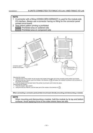
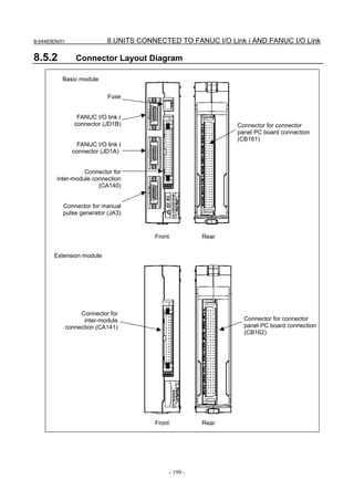
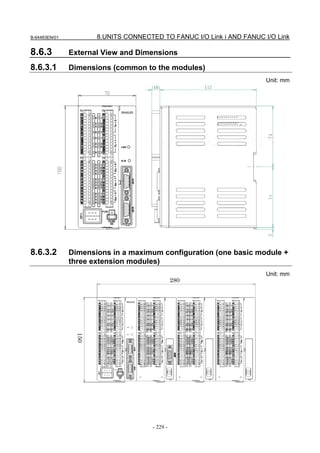
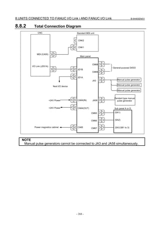
![B-64483EN/01 8.UNITS CONNECTED TO FANUC I/O Link i AND FANUC I/O Link
• When the modules are directly connected to the connection printed circuit board designed by
the machine tool builder:
Install the extension modules to the right of the basic module on the installation plane.
• When the modules are installed using DIN rails or screws:
Install the extension modules to the left of the basic module on the installation plane.
Power supply rating
Module Power supply voltage Power supply rating Remarks
Basic module 24 VDC ±10% is fed through 0.2A+7.3mA×DI Number of DI
the I/O connector (CB150) of points with DI=ON
Expansion modules A and B the basic module; 0.1A+7.3mA×DI Number of DI
±10% includes momentary points with DI=ON
Expansion module C (2A output variations and ripples. 0.1A
module)
Expansion module D (analog input 0.1A
module)
As a guideline for the heat dissipation, assume [above power supply capacity × 24 (W)].
NOTE
1 The above power supply rating does not include that to be input to DOCOM for
DO output.
2 To connect an optical adapter for the I/O Link i to both connectors JD1A and
JD1B on the basic module, the above power supply rating + 70 mA is required
for the power supply of the basic module.
8.2.4 Connection of the Basic Module, and Extension Modules A
and B
8.2.4.1 Connector pin arrangement
The following figure shows the connector pin arrangement of the basic module and extension modules A
and B.
CB150(HONDA MRH-50RMAST)
- 147 -](https://image.slidesharecdn.com/b-64483en01-121206192203-phpapp02/85/B-64483-en-01-167-320.jpg)


![B-64483EN/01 8.UNITS CONNECTED TO FANUC I/O Link i AND FANUC I/O Link
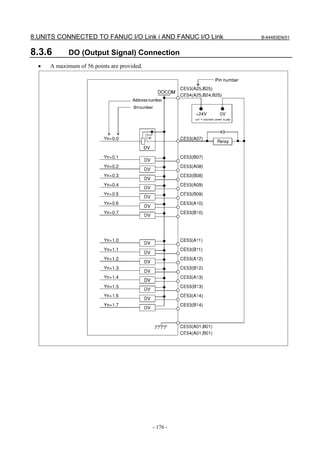
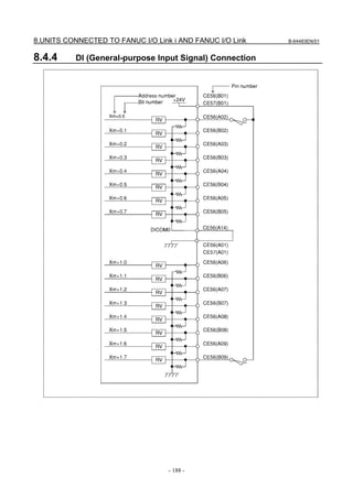
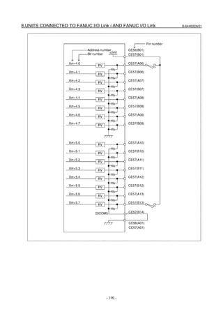
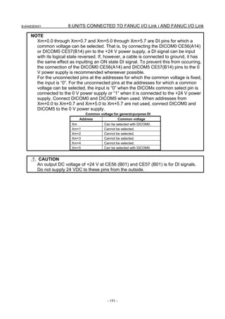
8.2.4.4 DI/DO Signal Specifications
This section describes the specifications of the DI/DO signals used with the basic module and expansion
modules A and B.
DI (input signal specifications)
Number of points 24 points (per module)
Contact rating 30 VDC, 16 mA or more
Leakage current between 1 mA or less (26.4 V)
contacts when opened
Voltage decrease between 2 V or less (including a cable voltage decrease)
contacts when closed
Delay time The receiver delay time is 2 ms (maximum). In addition, [I/O Link transfer time
between CNC and I/O module] and [ladder scan period (depending on CNC)]
must be considered.
DO (output signal specifications)
Number of points 16 points (per module)
Maximum load current when ON 200 mA or less including momentary variations
Saturation voltage when ON 1 V (maximum) when the load current is 200 mA
Withstand voltage 24 V +20% or less including momentary variations
Leakage current when OFF 20 μA or less
Delay time The driver delay time is 50 μs (maximum). In addition, [I/O Link transfer time
between CNC and I/O module] and [ladder scan period (depending on CNC)]
needs to be considered.
ON/OFF of the power supply for DO signals (output signals)
By turning off (opening) the power supply (DOCOM) for the DO signals (output signals), all the DO
signals of each module can be turned off at the same time. At this time, the DO state is as shown below.
ON
DOCOM
OFF
DO state when DO is ON
on in the sequence OFF
DO state when DO is ON
off in the sequence OFF
NOTE
When DO is on in the sequence, the ON/OFF state of DOCOM is directly reflected
in the DO state as indicated above by the dashed box.
Parallel DO (output signal) connection
A DO load current of twice the level can be obtained by connecting DO points in parallel and exercising
ON/OFF control at the same time in the sequence. Namely, the maximum load current per DO point is 200
mA. By connecting two DO points in parallel and turning on the two DO points at the same time, 400 mA
can be obtained. In this case, however, the leakage current is doubled up to 40 mA when the DO points are
turned off.
CAUTION
Be sure to connect the bit at the same address for parallel connection.
Do not connect three or more signals in parallel.
- 151 -](https://image.slidesharecdn.com/b-64483en01-121206192203-phpapp02/85/B-64483-en-01-171-320.jpg)
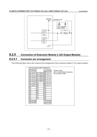

![8.UNITS CONNECTED TO FANUC I/O Link i AND FANUC I/O Link B-64483EN/01
8.2.5.3 2A output signal specifications
This subsection describes the specifications of the signals used with extension module C (2A output
module).
DO (output signal specifications)
Number of points 16 points (per module)
2 A or less per point.
Maximum load current when ON 12 A maximum for the entire module (DO: 16 points) (including
momentary variations).
Withstand voltage 24 V +20% or less (including momentary variations)
Leakage current when OFF 100 μA or less
The driver delay time is 120ns(MAX). In addition, [I/O Link transfer time
Delay time between CNC and I/O module] and [ladder scan period (depending on
CNC)] needs to be considered.
ON/OFF of the power supply for DO signals (output signals)
For ON/OFF of the power supply (DOCOMA) for the DO signals (output signals), see Subsection 8.2.4.4.
Parallel DO (output signal) connection
The 2A output module does not allow parallel DO connections.
8.2.6 Connection of Extension Module D (Analog Input Module)
8.2.6.1 Analog Input Connector Pin Allocation
This subsection describes the pin allocation of extension module D (analog input module).
CB150(HONDA MRH-50RMAST)
- 154 -](https://image.slidesharecdn.com/b-64483en01-121206192203-phpapp02/85/B-64483-en-01-174-320.jpg)

![8.UNITS CONNECTED TO FANUC I/O Link i AND FANUC I/O Link B-64483EN/01
NOTE
5 If the voltage (current) source has a GND pin, as shown in the figure above,
connect COMn to this pin. Otherwise, connect INMn and COMn together in the
analog input module.
8.2.6.3 Analog Input Signal Specifications
This subsection describes the specifications of the input signals used with extension module D (analog
input module).
Item Specifications Remarks
Number of input channels Four channels
(Note)
Analog input DC -10 to +10 V (Input resistance: 4.7 MΩ) Voltage input or current input
DC -20 to +20 mA (Input resistance: 250 Ω) can be selected on
channel-by-channel basis.
Digital output (Note) 12 bits (binary) Represented as two's
complement
Input/output correspondence
Analog input Digital output
+10V +2000
+5V or +20mA +1000
0V or 0mA 0
-5V or -20mA -1000
-10V -2000
Resolution 5 mV or 20 μA
Overall precision Voltage input: ±0.5% With respect to full scale
Current input: ±1%
Maximum input ±15V/±30mA
voltage/current
Minimum conversion time [I/O Link transfer time between CNC and I/O
module] and [ladder scan period (depending on
CNC)] needs to be considered.
Number of occupied DI = 3 bytes, DO = 2 bytes
input/output points (Note)
NOTE
Extension module D (analog input module) has four input channels. The digital
output section consists of a group of 12 bits within the three-byte occupied input
points. This means that the channel to be used can be dynamically selected by the
ladder. The channel switching DO point for channel selection is included in the
two-byte occupied output points.
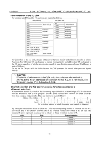
8.2.6.4 Channel selection and A/D conversion data
NOTE
For allocation, see Subsection 8.2.10.
(Channel selection)
With extension module D (analog input module), which of the four analog input channels is to be the
target of A/D conversion must be determined with a PMC program. The DO points used for this selection
are CHA and CHB (two-byte occupied output points). These are mapped as indicated below.
- 156 -](https://image.slidesharecdn.com/b-64483en01-121206192203-phpapp02/85/B-64483-en-01-176-320.jpg)


![B-64483EN/01 8.UNITS CONNECTED TO FANUC I/O Link i AND FANUC I/O Link
8.3.9 Specifications
Installation specifications
Install the I/O module in a fully enclosed cabinet.
For other installation conditions, conform to the CNC installation conditions.
Ordering specifications
Item Ordering specifications Remarks
I/O module for operator's panel A03B-0824-K200
Fuse (spare parts) A03B-0815-K001 1A
Module specifications
Item Specification Remarks
General-purpose DI 16 points 24-V input
Matrix DI 56 points (8 × 7) 5-V input
DO points 56 points (8 × 7) 24 V source type output
MPG interface Max. 3 units
Power supply rating
Module Supply voltage Current rating Remarks
24 VDC ±10% supplied from the The total power consumption of DI points
power supply connector CPD1. The is included. (This is true when all
I/O module for
allowance of ±10% should include 0.35A general-purpose DI points are turned on.)
operator's panel
instantaneous voltage and ripple The power consumption of DO points is
voltage. not included.
NOTE
To connect an optical adapter for the I/O Link i to both connectors JD1A and
JD1B, the above power supply rating + 70 mA is required.
DI (input signal specifications)
(General-purpose input signal)
Contact rating 30 VDC, 16 mA or more
Leakage current between contacts when
1 mA or less (26.4 V)
opened
Voltage decrease between contacts
2 V or less (including a cable voltage decrease)
when closed
The receiver delay time is 2 ms (maximum).
Delay time In addition, [I/O Link transfer time between CNC and I/O module] and
[ladder scan period (depending on CNC)] must be considered.
(Matrix input signal)
Contact rating 6 VDC, 2 mA or more
Leakage current between contacts when
0.2mA or less (6V)
opened
Voltage decrease between contacts
0.9 V or less (with a current of 1 mA)
when closed
The maximum matrix period of 16 ms (maximum).
Delay time In addition, [I/O Link transfer time between CNC and I/O module] and
[ladder scan period (depending on CNC)] must be considered.
- 181 -](https://image.slidesharecdn.com/b-64483en01-121206192203-phpapp02/85/B-64483-en-01-201-320.jpg)
![8.UNITS CONNECTED TO FANUC I/O Link i AND FANUC I/O Link B-64483EN/01
NOTE
When detour prevention diodes are used, the voltage drop across closed contacts
indicated above must be maintained, including the diode voltage drop.
DO (output signal specifications)
200 mA or less including momentary current per signal. 3.5 A or less for
Maximum load current when ON
DO signals in all
Saturation voltage when ON 1 V (maximum) when the load current is 200 mA
Withstand voltage 24 V +20% or less including momentary variations
Leakage current when OFF 20μA or less
The driver delay time is 50 μs (maximum).
Delay time In addition, [I/O Link transfer time between CNC and I/O module] and
[ladder scan period (depending on CNC)] must be considered.
NOTE
Be sure to connect all DO power supply pins DOCOM.
8.3.10 Other Notes
Address allocation
For connection to the I/O Link i
For the I/O module for operator’s panel, I/O addresses are mapped as follows.
DI space map DO space map
Xm1 General-purpose Yn1
Xm1 + 1 input signal Yn1 + 1
Xm1 + 2 Yn1 + 2
Reserved
Xm1 + 3 Yn1 + 3 Output signal
Slot 1
Xm1 + 4 Yn1 + 4
Xm1 + 5 Yn1 + 5
Slot 1
Xm1 + 6 Yn1 + 6
Xm1 + 7 Matrix input signal Yn1 + 7 Reserved
Xm1 + 8
Xm1 + 9
Xm1 + 10
Xm1 + 11 Reserved
Xmmpg (for 1st MPG)
Xmmpg + 1 (for 2nd MPG) Basic module Slot MPG
Xmmpg + 2 (for 3rd MPG)
Xm1, Xmmpg, and Yn1 indicate the start address at allocation.
Basically, for an I/O module for operator’s panel, allocate 12-byte DI addresses to slot 1 and 8-byte DO
addresses to slot 1.
An I/O module for operator’s panel has an interface for three manual pulse generators. To use manual
pulse generators, allocate addresses to slot MPG. With this setting, addresses can be allocated to the three
manual pulse generators at a time (addresses cannot be allocated individually to manual pulse generators).
Do not use the addresses with the ladder because the CNC processes the manual pulse generator signals
directly.
- 182 -](https://image.slidesharecdn.com/b-64483en01-121206192203-phpapp02/85/B-64483-en-01-202-320.jpg)


![B-64483EN/01 8.UNITS CONNECTED TO FANUC I/O Link i AND FANUC I/O Link
8.4.8 Specifications
Installation specifications
Install the I/O module in a fully enclosed cabinet.
For other installation conditions, conform to the CNC installation conditions.
Ordering specifications
Item Ordering specifications Remarks
DI : 48 points
I/O module for operator’s panel
A03B-0824-K202 DO : 32 points
(with MPG interface)
With MPG interface
DI : 48 points
I/O module for power magnetics cabinet
A03B-0824-K203 DO : 32 points
(without MPG interface)
Without MPG interface
Fuse (spare parts) A03B-0815-K001 1A
Module specifications
Item Specification Remarks
DI points 48 points 24-V input
DO points 32 points 24 V source type output
MPG interface Max. 3 units For A03B-0824-K202
Power supply rating
Power supply
Module Supply voltage Remarks
rating
I/O module for operator’s 24 VDC ±10% supplied from the power 0.3A+7.3mA×DI DI = number of DI
panel and I/O module for supply connector CPD1. The allowance points in the ON state
power magnetics cabinet of ±10% should include instantaneous
voltage and ripple voltage.
NOTE
To connect an optical adapter for the I/O Link i to both connectors JD1A and
JD1B, the above power supply rating + 70 mA is required.
DI (input signal specifications)
(General-purpose input signal)
Contact rating 30 VDC, 16 mA or more
Leakage current between contacts when
1 mA or less (26.4 V)
opened
Voltage decrease between contacts
2 V or less (including a cable voltage decrease)
when closed
The receiver delay time is 2 ms (maximum).
Delay time In addition, [I/O Link transfer time between CNC and I/O module] and
[ladder scan period (depending on CNC)] must be considered.
DO (output signal specifications)
200 mA or less including momentary current per signal. 5.6 A or less for
Maximum load current when ON
DO signals in all
Saturation voltage when ON 1 V (maximum) when the load current is 200 mA
Withstand voltage 24 V +20% or less including momentary variations
Leakage current when OFF 20μA or less
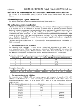
- 195 -](https://image.slidesharecdn.com/b-64483en01-121206192203-phpapp02/85/B-64483-en-01-215-320.jpg)
![8.UNITS CONNECTED TO FANUC I/O Link i AND FANUC I/O Link B-64483EN/01
The driver delay time is 50 μs (maximum).
Delay time In addition, [I/O Link transfer time between CNC and I/O module] and
[ladder scan period (depending on CNC)] must be considered.
NOTE
Be sure to connect all DO power supply pins DOCOM.
8.4.9 Other Notes
Address allocation
- For connection to the I/O Link i
For this I/O module, I/O addresses are mapped as follows.
DI space map DO space map
Xm 1 Yn1
Xm 1 + 1 Yn1 + 1 Output signal
Slot 1
Xm 1 + 2 Input signal Yn1 + 2
Slot 1
Xm 1 + 3 Yn1 + 3
Xm 1 + 4
Xm 1 + 5
Xm mpg (for 1st MPG)
Xm mpg + 1 (for 2nd MPG) Manual pulse Slot MPG
Xm mpg + 2 (for 3rd MPG) generator
Xm1, Xmmpg, and Yn1 indicate the start address at allocation.
Basically, for this I/O module, allocate 6-byte DI addresses to slot 1 and 4-byte DO addresses to slot 1.
An I/O module for operator’s panel has an interface for three manual pulse generators. To use manual
pulse generators, allocate addresses to slot MPG. With this setting, addresses can be allocated to the three
manual pulse generators at a time (addresses cannot be allocated individually to manual pulse generators).
Do not use this area with the ladder because the CNC processes the manual pulse generator signals
directly.
- For connection to the I/O Link
DI space map DO space map
Xm Yn
Input signal
Xm+1 Yn+1 Output
Xm+2 Yn+2 signal
Xm+3 Yn+3
Xm+4
Xm+5
Xm+6 Not used
Xm+7
Xm+8
Xm+9
Xm+10
Xm+11
Xm+12 (for 1st MPG)
Xm+13 (for 2nd MPG) Manual pulse
Xm+14 (for 3rd MPG) generator
Xm+15(DO alarm DO alarm
detection) detection
For connection to the I/O Link, addresses are allocated to input signals, manual pulse generators, and DO
alarm detection at a time. For this reason, allocate DI addresses in units of 16 bytes.
Do not use the DI space with the ladder because the CNC processes the manual pulse generator signals
directly.
- 196 -](https://image.slidesharecdn.com/b-64483en01-121206192203-phpapp02/85/B-64483-en-01-216-320.jpg)


![B-64483EN/01 8.UNITS CONNECTED TO FANUC I/O Link i AND FANUC I/O Link
8.5.4 Module Specifications
Types of modules
Item Ordering specifications Specification
I/O module type-2 for connector panel (basic A03B-0824-C040 DI/DO=48/32
module B1) With MPG interface
I/O module type-2 for connector panel (basic A03B-0824-C041 DI/DO=48/32
module B2) Without MPG interface
I/O module type-2 for connector panel (extension A03B-0824-C042 DI/DO=48/32
module E1)
Fuse (spare parts) A03B-0815-K002 1 A (for basic module)
Inter-module flat cable A03B-0815-K102 Cable length: 35 mm
Module interval: 5 mm
NOTE
Be sure to use modules with the ordering specifications listed above in
combination. Do not use other modules.
Installation conditions
(1) Use this I/O module in a completely sealed cabinet.
(2) Use the units under the following ambient temperature conditions:
Operation: 0°C to 55°C
Storage and transportation: -20°C to 80°C
(3) For other installation conditions, conform to the CNC installation conditions.
(4) For ventilation within each I/O module, allow a clearance of 40 mm or more between modules.
Moreover, allow a clearance of 50 mm or more above and below each module. Never place a device
that generates a large amount of heat below an I/O module.
(5) When mounting I/O modules, ensure that the basic module is mounted on the left side when viewed
from the flat cable.
Power supply rating
Module Supply voltage Power supply rating Remarks
Basic module 24 VDC ±10% is fed through CB161 and 0.3A+7.3mA×DI DI = number of DI
CB162; ±10% includes momentary points in the ON state
Extension module variations and ripples. 0.2A+7.3mA×DI DI = number of DI
points in the ON state
As a guideline for heat dissipation, assume [power supply rating × 24 (W)].
NOTE
1 The above power supply rating does not include that to be input to DOCOM for
DO output.
2 To connect an optical adapter for the I/O Link i to both connectors JD1A and
JD1B on the basic module, the above power supply rating + 70 mA is required
for the power supply of the basic module.
- 201 -](https://image.slidesharecdn.com/b-64483en01-121206192203-phpapp02/85/B-64483-en-01-221-320.jpg)


![8.UNITS CONNECTED TO FANUC I/O Link i AND FANUC I/O Link B-64483EN/01
8.5.8 DI/DO Signal Specifications
This subsection describes the specifications of the DI/DO signals used with the basic module and
extension modules.
DI (input signal specifications)
Number of points 48 points (per module)
Contact rating 30 VDC, 16 mA or more
Leakage current between contacts 1 mA or less (26.4 V)
when opened
Voltage decrease between 2 V or less (including a cable voltage decrease)
contacts when closed
Delay time The receiver delay time is 2 ms (maximum).
In addition, [I/O Link transfer time between CNC and I/O module] and [ladder
scan period (depending on CNC)] must be considered.
DO (output signal specifications)
Number of points 32 points (per module)
Maximum load current when ON 200 mA or less including momentary variations
Saturation voltage when ON 1 V (maximum) when the load current is 200 mA
Withstand voltage 24 V +20% or less including momentary variations
Leakage current when OFF 20μA or less
Delay time The driver delay time is 50 μs (maximum).
In addition, [I/O Link transfer time between CNC and I/O module] and [ladder
scan period (depending on CNC)] must be considered.
ON/OFF of the power supply (DO common) for DO signals (output signals)
For ON/OFF of the power supply pin (DOCOM) for the DO signals (output signals), see Subsection
8.2.4.4.
Parallel DO (output signal) connection
For parallel connections of DO signals (output signals), see Subsection 8.2.4.4.
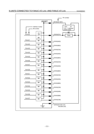
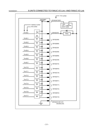
8.5.9 Power Supply Connection
+24V CB161(A32,B32,C32)
CB162(A32,B32,C32)
+24V 0V
+24V stabilized power supply
CB161(A31,B31,C31, A30,B30,C30)
0V CB162(A31,B31,C31, A30,B30,C30)
- 214 -](https://image.slidesharecdn.com/b-64483en01-121206192203-phpapp02/85/B-64483-en-01-234-320.jpg)


![B-64483EN/01 8.UNITS CONNECTED TO FANUC I/O Link i AND FANUC I/O Link
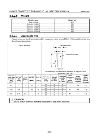
8.6.2.2 Installation conditions
(1) Use this I/O module in a completely sealed cabinet.
(2) Use the units under the following ambient temperature conditions:
Operation: 0°C to 55°C
Storage and transportation: -20°C to 80°C
(3) For other installation conditions, conform to the CNC installation conditions.
(4) Be sure to install this module on a vertical surface and provide a clearance of 100 mm or more both
above and below the module. Do not place equipment that generates a large amount of heat below
the I/O module.
8.6.2.3 I/O signal specifications
Basic module、Extension modules A and B
Digital input
Number of points 24 points
Common 8 points/common (6 common terminals)
Rated input voltage 24 VDC (+10%, −10%)
Rated input current 7 mA (average)
Polarity Xm+0.0 to Xm+0.7: Sink or source type selectable
Xm+1.0 to Xm+1.7, Xm+2.0 to Xm+2.7: Sink type
ON voltage/current 20 VDC or more, 6 mA or more
OFF voltage/current 8 VDC or less, 1.5 mA or less
Response time The receiver delay time is 2 ms (maximum).
In addition, [I/O Link transfer time between CNC and I/O module] and
[ladder scan period (depending on CNC)] needs to be considered.
Digital output
Number of points 16 points
Common 8 points/common (8 common terminals)
Rated output voltage 12 VDC to 24 VDC (+20%, −15%)
Rated output current 0.2A/pt
Polarity Source type
Maximum voltage decrease when ON 0.63 V (load current × 1.25Ω)
Maximum leakage current when OFF 40 μA
Output protection function Protection against overheat and overcurrent
Response time The driver delay time is 50 μs (maximum).
In addition, [I/O Link transfer time between CNC and I/O module] and
[ladder scan period (depending on CNC)] needs to be considered.
Extension module C
Digital output
Number of points 16 points
Common 4 points/common
Rated output voltage 12 VDC to 24 VDC (+20%, −15%)
Rated output current 2 A/pt (4 A/common)
Polarity Source type
Maximum voltage decrease when ON 0.18 V (load current × 0.09Ω)
Maximum leakage current when OFF 0.1mA
Insulation method Photocoupler insulation
Output protection function Protection against overheat, overcurrent, short-circuiting, and
disconnection detection
- 225 -](https://image.slidesharecdn.com/b-64483en01-121206192203-phpapp02/85/B-64483-en-01-245-320.jpg)
![8.UNITS CONNECTED TO FANUC I/O Link i AND FANUC I/O Link B-64483EN/01
Digital output
Response time The driver delay time is 50 μs (maximum).
In addition, [I/O Link transfer time between CNC and I/O module] and
[ladder scan period (depending on CNC)] needs to be considered.
Extension module D
Analog input
Number of input channels 4 channels
Analog input range -10 VDC to +10 VDC Voltage input or current input can
(Input resistance: 4.7 MΩ) be selected on a
-20 VDC to +20 mA channel–by–channel basis by
(Input resistance: 250Ω) wiring.
Digital conversion range 12 bits (binary), two's complement representation
Input/output correspondence
Analog input Digital output
+10V +2000
+5V or +20mA +1000
0V or 0mA 0
-5V or -20mA -1000
-10V -2000
Resolution 5 mV or 20 μA
Overall precision Voltage input: ±0.5% (with respect to full scale)
Current input: ±1.0% (with respect to full scale)
Maximum input voltage/current ±15 V/±30 mA
A-D conversion time 2 ms or less
Minimum update period of digital output Ladder scan period of CNC connected
Number of occupied input/output points DI = 3 bytes, DO = 2 bytes(NOTE)
CAUTION
This module has four analog input channels but has only one 12-bit digital output
channel within the occupied input points (3 bytes). Namely, a channel for
conversion is selected dynamically using a ladder program. Channel switching DO
points for selecting a channel are present in the occupied output points (2 bytes).
(See Item, “Channel selection and A/D conversion data for extension module D” in
the Subsection 8.6.6.1, “Address map”.)
Extension module E
Analog output
(Note 1)
Number of input channels 4 channels
Analog output range (Note 2) -10 VDC to +10 VDC (external load resistance 10kΩ or more)
0 VDC to +20 mA (external load resistance 400Ω or less)
Digital conversion range 12 bits (binary), two's complement representation
Input/output correspondence
Analog output
Digital input
Voltage output Current output
+2000 +10V -
+1000 +5V +20mA
0 0V 0mA
-1000 -5V -
-2000 -10V -
Resolution 5 mV or 20 μA
Overall precision Voltage input: ±0.5% (with respect to full scale)
Current input: ±1.0% (with respect to full scale)
D-A conversion time (Note 3) 1ms or less
Minimum update period of digital output Ladder scan period of CNC connected
- 226 -](https://image.slidesharecdn.com/b-64483en01-121206192203-phpapp02/85/B-64483-en-01-246-320.jpg)
![B-64483EN/01 8.UNITS CONNECTED TO FANUC I/O Link i AND FANUC I/O Link
Analog output
Number of occupied input/output points (Note 4) DI = 3 bytes, DO = 2 bytes(NOTE)
CAUTION
1 One of the four channels must be selected for output using a ladder program.
(See Item, “Channel selection and D/A conversion data for extension module E”
in the Subsection 8.6.6.1, “Address map”.)
2 There is a choice between use for voltage output or use for current output during
connection to the terminal section.
3 The conversion time refers to that only within the module. The actual response
time includes the scan time determined depending on the system.
4 The 3 DI bytes are automatically occupied at assignment, but not used. (See
Item, “Channel selection and D/A conversion data for extension module E” in the
Subsection 8.6.6.1, “Address map”.)
8.6.2.4 Power supply rating
Module name Supply voltage Current rating
Basic module 24 VDC ±10% 0.2 A + 7.3 mA × DI
(DI: Number of DI points in the ON state)
Extension modules A,B Supplied from the basic module 0.1 A + 7.3 mA × DI
(DI: Number of DI points in the ON state)
Extension module C Supplied from the basic module 0.1A
Extension module D Supplied from the basic module 0.1A
Extension module E Supplied from the basic module 0.16A
CAUTION
1 The above power supply rating does not include that to be input to DOCOM0
and DOCOM1 for DO output.
2 To connect an optical adapter for the I/O Link i to both connectors JD1A and
JD1B on the basic module, the above power supply rating + 70 mA is required
for the power supply of the basic module.
8.6.2.5 Heat dissipation
The heat dissipation of a module is the sum of "Basic heat dissipation" in the table below plus the total
obtained by multiplying each of "Heat dissipation per input point" and "Heat dissipation per output point"
in the table below by the number of points that are turned on at the same time.
Heat dissipation per
Basic heat dissipation Heat dissipation per
Module name output point (W)
(W) input point (W)
IL: Output load current
Basic module 4.8 0.23 0.04+0.9×IL2
Extension modules A, B 2.4 0.23 0.04+0.9×IL2
Extension module C 2.4 - 0.04+0.1×IL2
Extension module D 2.4 - -
Extension module E 3.8 - -
[Calculation example]
When 16 input points, eight 0.1-A output points, and four 0.2-A output points are used for the basic
module, and eight 2-A output points are used for extension module C
P=4.8+0.23×16+(0.04+0.9×0.12)×8+(0.04+0.9×0.22)×4+1.0+(0.04+0.09×22)×8
=13.4W
- 227 -](https://image.slidesharecdn.com/b-64483en01-121206192203-phpapp02/85/B-64483-en-01-247-320.jpg)


![B-64483EN/01 8.UNITS CONNECTED TO FANUC I/O Link i AND FANUC I/O Link
8.7.2 Specification
Item Specification
I/O Link function Provided with two slave mode I/O Link interface channels, between which DI/DO data can be
transferred.
[Interface types]
Electrical - optical
Electrical - electrical One of the following combinations is selected:
Optical - optical
Number of DI/DO data DI: Up to 256, DO: Up to 256
items (The number of data items actually used varies depending on the amount of data
assigned in the host.)
Power supply Each I/O Link interface must be independently supplied with +24 VDC.
Voltage: +24 VDC ±10%
Current: 0.2 A (excluding surge)
If a master unit does not have sufficient capacity to supply power to each unit (0.2 A per
slot), use an external power supply unit. The power supply must be switched on,
either simultaneously with or before, the I/O Link master.
The two systems can be switched on and off independently of each other. Data from
a system to which no power is supplied appears as zeros when viewed from the other
system. The data becomes 0 within 200 ms of the power being switched off.
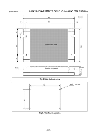
External dimensions 180 mm (width) × 150 mm (height) × about 50 mm (depth)
W H D
Fig. 8.7.2 (b) is an outline drawing of the unit.
Installation The unit, which is a stand-alone type, is installed in the power magnetics cabinet. Fig.
8.7.2 (c) shows how to mount the unit.
Operating environment Temperature : 0 to 60°C
Humidity : 5 to 75% RH (non-condensing)
Vibration : 0.5 G or less
Ordering information
Interface type Specification
Electrical-optical interface A20B-2000-0410
Electrical-electrical interface A20B-2000-0411
Optical-optical interface A20B-2000-0412
- 261 -](https://image.slidesharecdn.com/b-64483en01-121206192203-phpapp02/85/B-64483-en-01-281-320.jpg)

![8.UNITS CONNECTED TO FANUC I/O Link i AND FANUC I/O Link B-64483EN/01
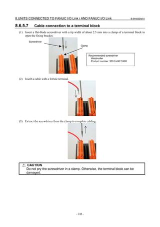
8.7.3 Connection
8.7.3.1 I/O Link interface
(1) Connection diagram (example)
AC power input AC power input
External power External power
(+24 V) (+24 V)
I/O Link master I/O Link master
③ ③
① ①
JD1A JD1A
(JD51) (JD51)
Optical I/O
Link adapter
CP* CP*
②
Electrical Optical
interface interface
JD1B* COPB*
JD1A* COPA*
① ②
FANUC I/O Link connection unit (for
electrical-optical interface)
(*) 1 or 2 (channel No.)
<1> : Signal cable (electrical)
<2> : Signal cable (optical) Additionally, the FANUC I/O Link connection unit frame must be grounded.
<3> : Power supply cable
[Name of I/O Link connection unit connectors]
Electrical-optical Electrical-electrical Optical-optical
Connector name Connector name Connector name
I/O Link interface I/O Link interface I/O Link interface
Channel 1 Channel 2 Channel 1 Channel 2 Channel 1 Channel 2
JD1A1 COPA2 JD1A1 JD1A2 COPA1 COPA2
JD1B1 COPB2 JD1B1 JD1B2 COPB1 COPB2
CP1 CP2 CP1 CP2 CP1 CP2
(2) Signal cable (electrical)
For connection of the signal cable (electrical), see Subsection 7.2.1, “Connection of I/O Link i or I/O
Link by Electric Cable”.
Since the electrical interface of this unit has no +5 V power supply, the optical adapter cannot be
connected.
If you want to use an optical interface, place an order on an I/O Link connection unit with an optical
interface.
(3) Signal cable (optical)
For connection of the signal cable (optical), see Subsection 7.2.2, “Connection of FANUC I/O Link i
or I/O Link by Optical Fiber Cable”.
The optical interface of an I/O Link connection unit is equivalent to an optical adapter (normal type).
- 264 -](https://image.slidesharecdn.com/b-64483en01-121206192203-phpapp02/85/B-64483-en-01-284-320.jpg)


![8.UNITS CONNECTED TO FANUC I/O Link i AND FANUC I/O Link B-64483EN/01
8.8.10.6 Heat output
Heat output Remarks
15W When 50% of general-purpose input signals and key LEDs on the main panel are on
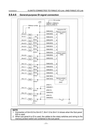
8.8.10.7 General-purpose DI signal definition
Contact rating 30 VDC, 16 mA or more
Leakage current between
1 mA or less (26.4 V)
contacts when opened
Voltage decrease between
2 V or less (including a cable voltage decrease)
contacts when closed
The receiver delay time is 2 ms (maximum). In addition, [I/O Link transfer time
Delay time between CNC and I/O module] and [ladder scan period (depending on CNC)] must
be considered.
8.8.10.8 General-purpose DO signal definition
Maximum load current when 200 mA or less including momentary variations
ON
Saturation voltage when ON 1 V (maximum) when the load current is 200 mA
Withstand voltage 24 V +20% or less including momentary variations
Leakage current when OFF 5μA 以下
The driver delay time is 50 μs (maximum). In addition, [I/O Link transfer time
Delay time between CNC and I/O module] and [ladder scan period (depending on CNC)] needs
to be considered.
Output protection function Protection against overheat, overcurrent, and short-circuiting (for each point)
8.8.11 Key Tops on the Main Panel
8.8.11.1 Meaning of key symbols
Symbol English Meaning of key
AUTO AUTO mode selection signal; Sets automatic operation mode.
EDIT EDIT mode selection signal; Sets program edit operation mode.
MDI MDI mode selection; Sets MDI mode.
REMOTE DNC operation mode; Sets DNC operation mode.
REF Reference position return mode selection; Sets reference position return
RETURN mode.
JOG JOG feed mode selection; Sets jog feed mode.
INC
Step feed mode selection; Sets step feed mode.
JOG
HANDLE Manual handle feed mode selection; Sets manual handle feed mode.
Teach-in jog (reach-in handle) mode selection signal; Sets teach-in jog
TEACH
(teach-in handle) mode.
SINGLE Single block signal; Executes program one by one. This key is used to check
BLOCK a program.
- 284 -](https://image.slidesharecdn.com/b-64483en01-121206192203-phpapp02/85/B-64483-en-01-304-320.jpg)


![11.CONNECTION FOR PERSONAL COMPUTER FUNCTION WITH Windows® CE B-64483EN/01
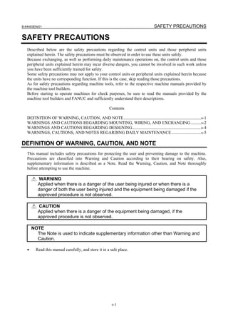
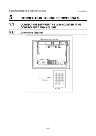
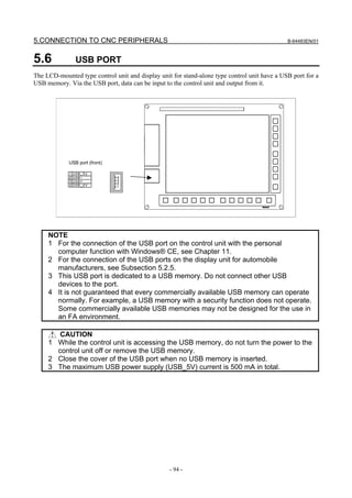
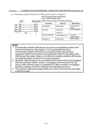
11.3.3.4 USB port (front side)
This port is used to connect a USB keyboard or USB printer.
USB port (front)
NOTE
1 Commercially available USB devices are prone to compatibility problems with
personal computers to some degree. It is not guaranteed that every
commercially available USB device can operate properly with personal
computers. Machine tool builders are requested to check the operability of the
USB devices they select. Keep in mind that commercially available USB devices
are generally neither dust-proof nor moisture-resistant.
2 The USB port on the front side allows a device to be connected to the port with
the power kept on (hot plugging).
3 The maximum USB power supply (USB_5V) current on the front and rear sides
is 500 mA in total.
11.3.4 High-speed Serial Bus (HSSB) [For Stand-alone Type]
For details of the optical fiber cable and relay adapter, see Appendix D.
- 334 -](https://image.slidesharecdn.com/b-64483en01-121206192203-phpapp02/85/B-64483-en-01-354-320.jpg)