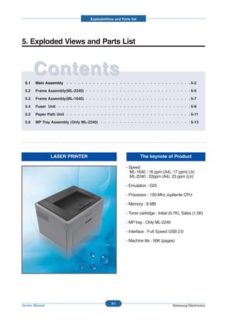
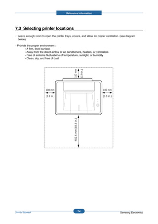
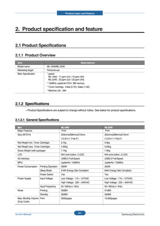
This document provides specifications and information for the ML-1640 and ML-2240 laser printers. It includes details on:
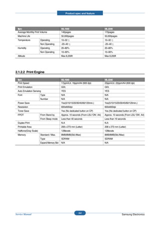
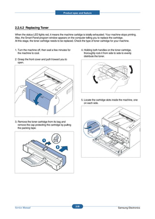
- Speeds of 16ppm and 22ppm for the ML-1640 and ML-2240 respectively.
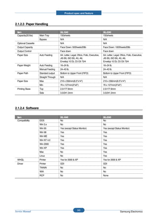
- Interfaces including USB 2.0 and optional multi-purpose tray for the ML-2240.
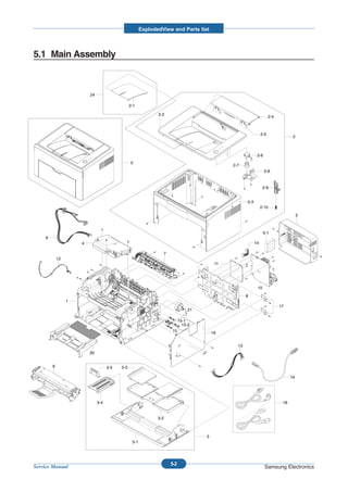
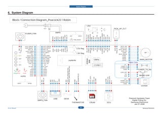
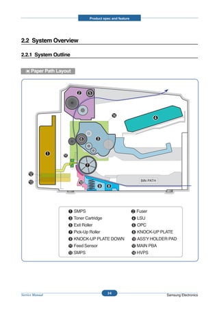
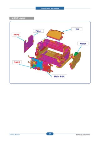
- Hardware components including the main PBA, fuser unit, and HVPS board.
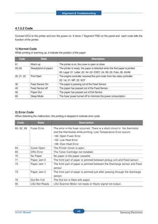
- Safety precautions for handling toner, avoiding electric shock, and laser safety.
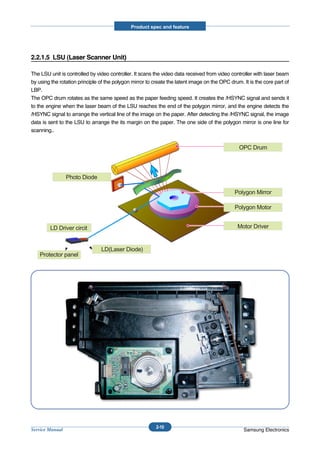
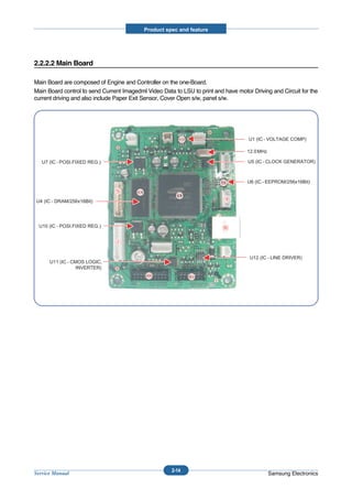
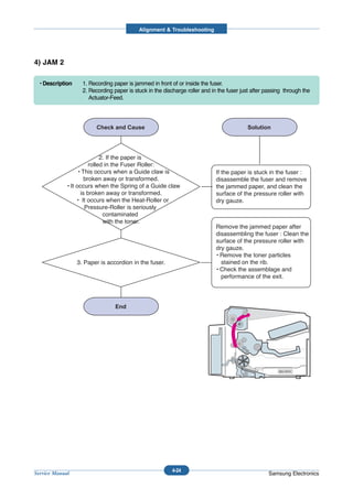
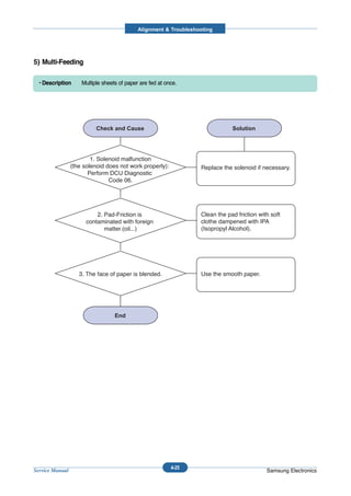
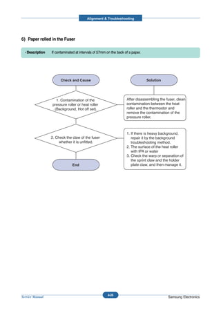
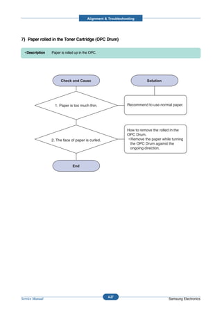
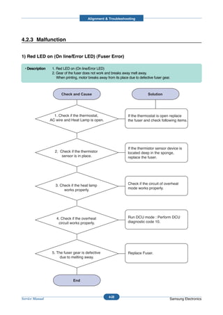
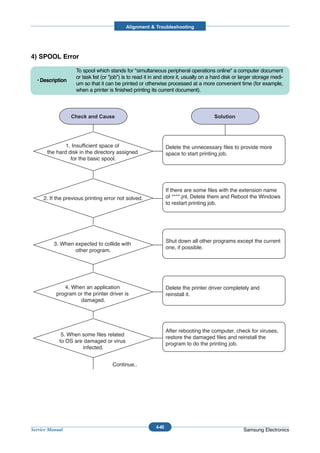
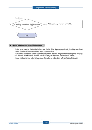
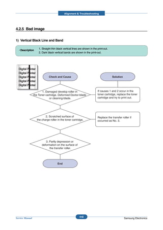
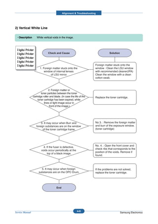
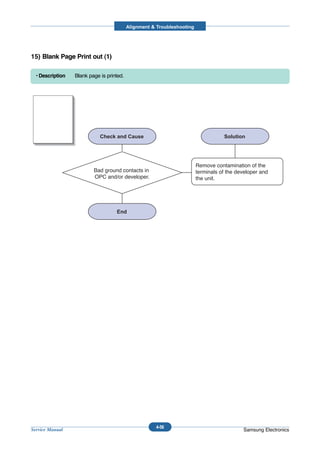
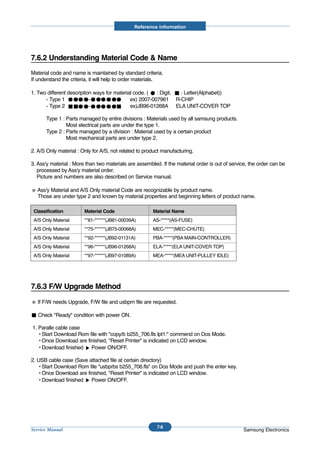
![Alignment & Troubleshooting
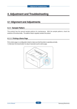
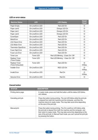
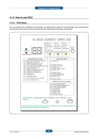
4.1.5.3 Self Diagnostic Mode
If Error code occurs due to malfunction of the printer, perform Self Diagnostic Mode to solve the problem.
The printer works only in the self-test mode to solve the malfunction problem.
To enter the self-test mode, turn the power on pressing the buttons of [Down], [Shift] and [Stop] at the same time.
Release the button within 2 or 3 seconds if 78 shows in the DCU. If 00 shows in the DCU, press the button [Up] or
[Shift] to select the self+test , and press the button of [Enter] to operate. To stop, press the button of [shift] and
[Enter] together.
Code Description
00 Main Motor Operating System
Only the main motor is in operation.
01 Main High Voltage On(THV-)
-1400 voltage output by MHV terminal.
Caution : High voltage probe should be used.
02 Transfer High Voltage(-)On(THV-)
-1000 voltage output by MHV terminal.
Caution : High voltage probe should be used.
03 Transfer High Voltage (+)Reference on (THV +)
+1300 voltage output by MHV terminal.
Caution : High voltage probe should be used.
04 DEV/supply High Voltage : DEV/Supply High Voltage Test.
The left one of the three LEDs in the self-test panel is on when DEV high voltage Supply
high voltage output by each HV terminal. Press the [Up] button to switch the voltage. The
middle and right one of the three LEDs are on and -350 voltage output by DEV HV
terminal.
Caution : High voltage probe should be used.
05 LSU Operating System
The scanning motor of LSU is in operation, the right LED of the three buttons on. Press
the [Up] button to Check LD. LD is functioning and the middle button is on. If the LD is
normal, all LEDs are on.
06 Pickup clutch on
The Solenoid in the printer is in operation. To stop the operation, Press the button [shift]
and [Enter] together.
4-10
Service Manual Samsung Electronics](https://image.slidesharecdn.com/samsungml-1640ml-2240sm-120327235945-phpapp01/85/Samsung-ml-1640-ml-2240_sm-60-320.jpg)
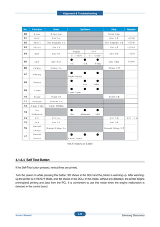
![Alignment & Troubleshooting
Code Description
07 Paper Empty Sensor Test :
If activate the Actuator of the PEMPTY Sensor, the left and right of the three LEDs are
on.
Paper Empty Sensor ON/OFF 1st LED ON/OFF
08 Feed & Exit Sensor Test
Test the Feed sensor and Discharge sensor in the same way as '07'.
Feed Sensor ON/OFF 2nd LED ON/OFF
Exit Sensor ON/OFF 3rd LED ON/OFF
09 Cover Open Sensor Test
Test the Cover Open Sensor in th same way as code '07’
Cover Open Sensor ON/OFF1st LED ON/OFF
10 Fuser Test
If the [Enter] button pressed, the right LED is on and temperature of the fuser is up to
READY Mode. If the [Up] button pressed, the middle LED is on and temperature of the
fuser is up to Printing Mode.
If you press the button once more, the left LED is on and temperature of the fuser is up to
overheat Mode.
11 Hot Burn Test
If the [enter] button pressed, the printer is continuously printing without detection.
Turn the power off to stop operation.
12 Cleaning Mode Print Mode
Print the paper to clean the OPC Drum in the Cartridge.
13 THV(+) TRIGGER. ALL HV :
All high voltage output by each HV terminal and LSU and the fan is in operation. In this
mode, electronic resistance of transfer roller and high voltage is detected.
14 PTL Test : (ML-1610 : not design)
Indicates the function of the PTL, same method of the code ‘07’.
15 Fan Test :
Indicates the function of the Fan, same method of the code ‘07’.
16 Manual Pickup Test :
Indicates the function of th Manual Pickup, same method of the code ‘07’.
17 Manual Sensor Test :
Indicates the function of the Manual Sensor, same method of the code ‘07’.
4-11
Service Manual Samsung Electronics](https://image.slidesharecdn.com/samsungml-1640ml-2240sm-120327235945-phpapp01/85/Samsung-ml-1640-ml-2240_sm-61-320.jpg)