Downloaded 43 times


![1General configuration
Contents of the structural equipment 1-2
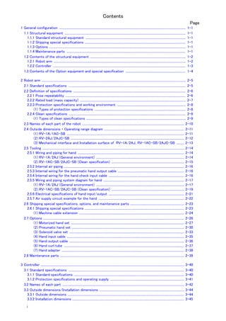
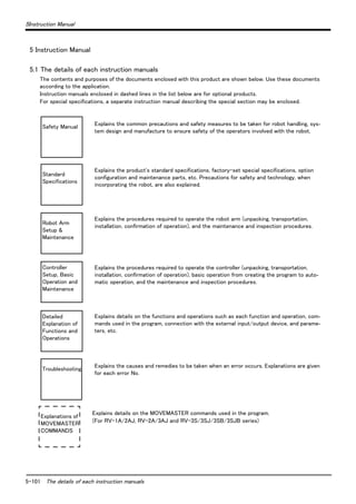
1.2 Contents of the structural equipment
1.2.1 Robot arm
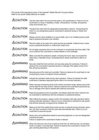
The list of structural equipment is shown in Fig. 1-1.
Fig.1-1 : Structural equipment (Robot arm)
Vertical six-axis
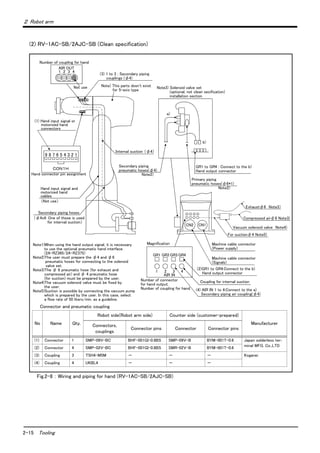
RV-1A:General environment
RV-1AC-SB:Clean specification
Hand output cable
・ 1E-GR35S
Hand input cable
・ 1A-HC20
Solenoid valve set
With installation bolts.
<sink type>
・ 1 set: 1E-VD01
・ 2 set: 1E-VD02
<source type>
・ 1 set: 1E-VD01E
・ 2 set: 1E-VD02E
Note) Not clean specification
Hand curl tube
・ 1 set, 2pc. : 1E-ST0402C
・ 2 set, 4pc. : 1E-ST0404C
Pneumatic hand set :
4A-HP01(sink type)/4A-HP01E (source type)
The set consists of the following parts.
・ Pneumatic hand : 1A-HP01/1A-HP01E
・ Solenoid valve set (1 pc.) : 1E-VD01/1E-VD01E
・ Curl cable : 1A-GHCD/1A-GHCD
・ Hand curl tube : 1A-ST0402C/1A-ST0402C
・ Pneumatic hand I/F : 2A-RZ365/2A-RZ375
・ Hand adapter : 1A-HA01/1A-HA01
With installation bolts.
Note) Not clean specification
or
Motorized hand set : 4A-HM01
・ Motorized hand : 1A-HM01
・ Curl cable : 1A-GHCD
・ Motorized hand I/F : 2A-RZ364
・ Hand adapter : 1A-HA01
With installation bolts.
Note) Not clean specification
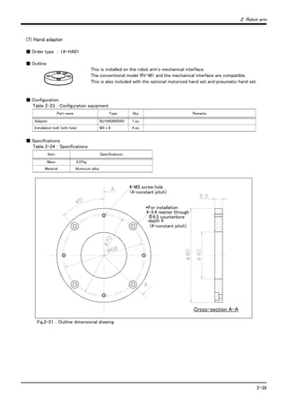
Hand adapter
: 1A-HA01
With installation bolts.
Vertical five-axis
multiple-jointed type
RV-2AJ:General environment
RV-2AJC-SB:Clean specification
Machine cable fixed type 5m
・ 1A-5CBL-1
Machine cable
・ Fixed type:1A- □□ CBL-1
・ Flexed type:1A- □□ LCBL-1
Note) □□ refer the length.
Refer to section "1.3" for datails.
Pneumatichandcustomer-manufacturedparts
[Caution]
Standard configuration
Special shipping
Option
equipment
specifications
Prepared by customer](https://image.slidesharecdn.com/rv1a-130719143349-phpapp02/85/Rv1-a-2aj-specs-bfp-a8050k-15-320.jpg)
![1-3 Contents of the structural equipment
1General configuration
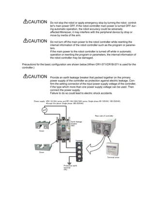
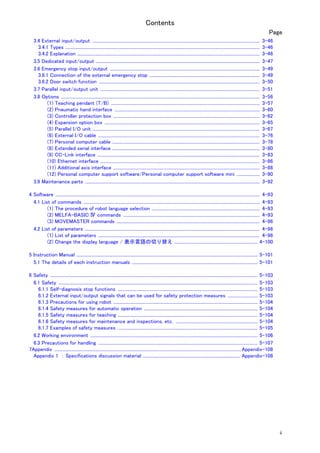
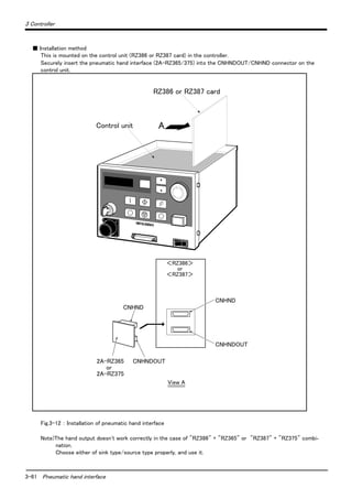
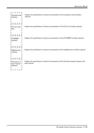
1.2.2 Controller
The devices shown below can be installed on the controller.
Personal computer
Preparedby customer
Controller
・ CR1B-571
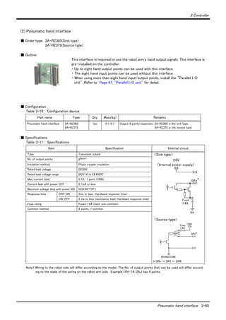
Pneumatic I/F
・ 2A-RZ365 (Sink)
・ 2A-RZ375 (Source)
Personal computer
cable
・ RS-MAXY-CBL
・ RS-AT-RCBL
Personal computer support software
(MS-Windows95/98/NT4.0)
・ 3A-01C-WINE(CD-ROM)
Personal computer support software
mini
(MS-Windows95/98/NT4.0)
・ 3A-02C-WINE(CD-ROM)
Teaching pendant
(T/B)
・ R28TB
Parallel I/O unit
・ 2A-RZ361 (Sink)
・ 2A-RZ371 (Source)
External I/O cable
・ 2A-CBL05 (5m)
・ 2A-CBL15 (15m)
E x p a n s i o n
option box
・ CR1-EB3
Extended serial
I/F
・ 2A-RZ581E
ETHERNET I/F
・ 2A-HR533E
PLC(Programmable
Logic Controller)
External device
Prepared by customer
CC-LINK I/F
・ 2A-HR575E
Additional axis
I/F
・ 2A-RZ541E
*1) There are some restrictions on the
number of optional interfaces and their
combinations.
Refer to the separate "Controller setup,
basic operation, and maintenance" for
details.
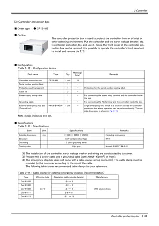
Controller protection box
・ CR1-MB
*1) *1) *1) *1)
Standard configuration
[Caution]
equipment
Special shipping
Option
specifications
Prepared by customer](https://image.slidesharecdn.com/rv1a-130719143349-phpapp02/85/Rv1-a-2aj-specs-bfp-a8050k-16-320.jpg)
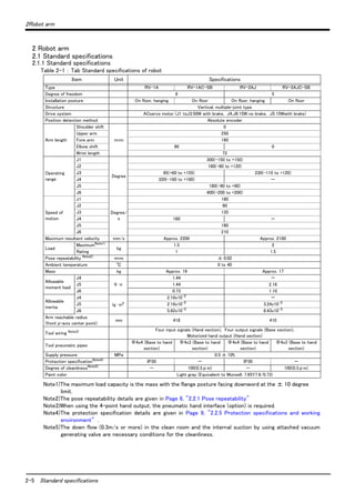
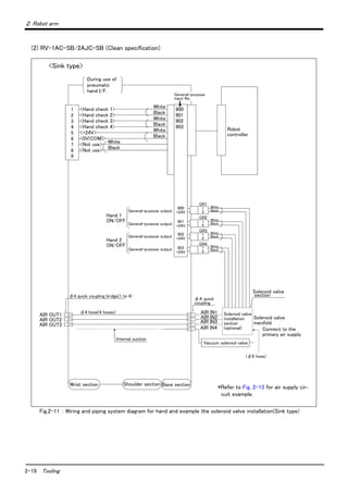
![2 Robot arm
Definition of specifications 2-6
2.2 Definition of specifications
The accuracy of pose repeatability mentioned in catalogs and in the specification manual is defined as follows.
2.2.1 Pose repeatability
For this robot, the pose repeatability is given in accordance with JIS 8432 (Pose repeatability). Note that the value
is based on 100 measurements (although 30 measurements are required according to JIS).
[Caution] The specified "pose repeatability" is not guaranteed to be satisfied under the following conditions.
[1] Operation pattern factors
1) When an operation that approaches from different directions and orientations are included in rela-
tion to the teaching position during repeated operations
2) When the speed at teaching and the speed at execution are different
[2] Load fluctuation factor
1) When work is present/absent in repeated operations
[3] Disturbance factor during operation
1) Even if approaching from the same direction and orientation to the teaching position, when the
power is turned OFF or a stop operation is performed halfway
[4] Temperature factors
1) When the operating environment temperature changes
2) When accuracy is required before and after a warm-up operation
[5] Factors due to differences in accuracy definition
1) When accuracy is required between a position set by a numeric value in the robot's internal coor-
dinate system and a position within the actual space
2) When accuracy is required between a position generated by the pallet function Note1)
and a posi-
tion within the actual space
Note1)
The pallet function is a function that teaches only the position of the work used as reference (3 to 4 points) and
obtains the remaining positions by calculations, for an operation that arranges works orderly or for an operation
that unloads orderly arranged works. By using this function, for example, in the case of an operation that arranges
works on grid points of 100 x 100, by teaching only three points of four corners, the remaining grid points are
automatically generated; thus, it is not necessary to teach all 10,000 points. For more information about the pallet
function, refer to the separate volume, "Instruction Manual/Detailed Explanation of Functions and Operations."](https://image.slidesharecdn.com/rv1a-130719143349-phpapp02/85/Rv1-a-2aj-specs-bfp-a8050k-19-320.jpg)
![2-7 Definition of specifications
2 Robot arm
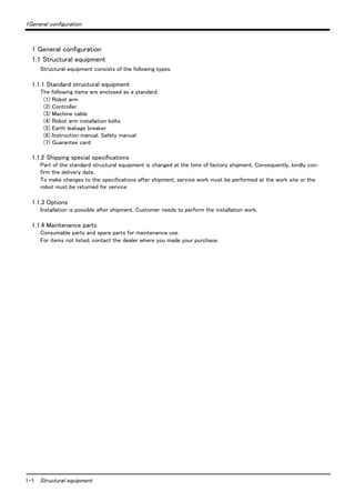
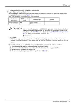
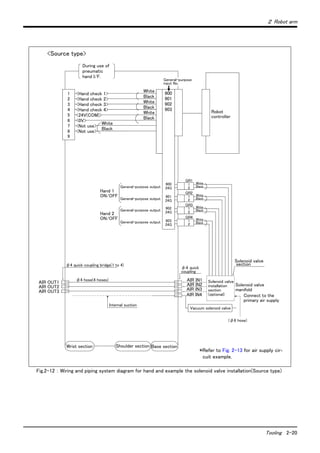
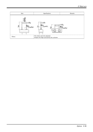
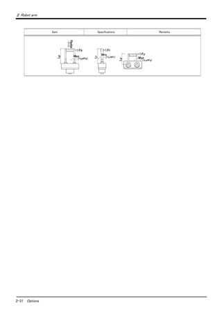
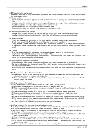
2.2.2 Rated load (mass capacity)
The robot's mass capacity is expressed solely in terms of mass, but even for tools and works of similar mass,
eccentric loads will have some restrictions. When designing the tooling or when selecting a robot, consider the fol-
lowing issues.
(1) The tooling should have the value less or equal than the smaller of the tolerable inertia and the tolerable
moment found in Page 5, "Table 2-1 : Tab Standard specifications of robot"
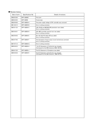
(2) Fig. 2-1 and Fig. 2-2shows the distribution dimensions for the center of gravity in the case where the vol-
ume of the load is relatively small. Use this figure as a reference when designing the tooling.
(3) When the load is not mass, but force, you should design the tooling so that it does not exceed the value for
allowable moment described in Page 5, "Table 2-1 : Tab Standard specifications of robot"
[Caution] The mass capacity is greatly influenced by the operating speed of the robot and the motion posture.
Even if you are within the allowable range mentioned previously, an overload or generate an overcurrnt
alarm could occur. In such cases, it will be necessary to change the time setting for acceleration/decel-
eration, the operating speed, and the motion posture.
[Caution] The overhang amount of the load for the specified moment and inertia in this section is the dynamic
limit value determined by the motor driving each axis and by the capacity of the reduction gears. Con-
sequently, accuracy cannot be guaranteed for the entire tooling area. Since accuracy is based on the
center point of the mechanical interface surface, position accuracy can diminish as you go away from
the flange surface, or vibration can result, with tooling that is not rigid or that is long.
Fig.2-1 : Position of center of gravity for loads (for loads with comparatively small volume) : RV-1A/1AC-SB
Fig.2-2 : Position of center of gravity for loads (for loads with comparatively small volume) : RV-2AJ/2AJC-SB
0150200250 100
100
150
136
100
150
72300
268 207 147 97
0.3kg
0.5kg
1.0kg
1.5
kg
136
106
106
75
50
50
75
Maximum load capacity
with the flange posture facing downword
Rotation center for J5 axis
Rotation center for J6 axis
100
150
250 200 150 100 72 0
100
150
300
0.5kg
1.0kg
1.5kg
2kg
129
129
91
91
75
75
56
56
254 180 147 110
Rotation center for J5 axis
Rotation center for J6 axis
Maximum load capacity
with the flange posture facing downword](https://image.slidesharecdn.com/rv1a-130719143349-phpapp02/85/Rv1-a-2aj-specs-bfp-a8050k-20-320.jpg)
![2 Robot arm
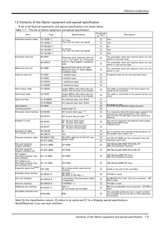
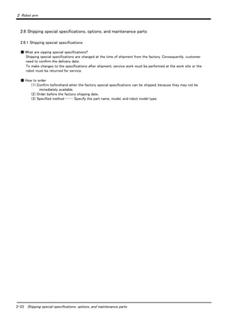
Shipping special specifications, options, and maintenance parts 2-24
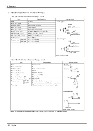
(1) Machine cable extension
■ Order type : ● Fixed type(10m) :1A-10CBL-1
● Fixed type(15m) :1A-15CBL-1
● Flexed type(5m) :1A-05LCBL-1
● Flexed type(10m) :1A-10LCBL-1
● Flexed type(15m) :1A-15LCBL-1
■ Outline
This cable is exchanged for the machine cable (5 m) that was supplied as standard to
extend the distance between the controller and the robot arm.
A fixed type and flexible type are available.
Exchanges after shipment will be charged (for packaging, shipping costs).
The fixing and flexible types are both configured of the motor signal cable and motor
power cable.
■ Configuration
Table 2-7 : Configuration equipments and types
Note) The numbers in the boxes □□ refer the length.
■ Specifications
The specifications for the fixed type cables are the same as those for standard cables.
Shows usage conditions for flexed type cables in Table 2-8.
Table 2-8 : Conditions for the flexed type cables
[Caution] The guidance of life count may greatly differ according to the usage state (items related to Table 2-8
and to the amount of silicon grease applied in the cable conduit.
[Caution] This option can be installed on clean-type, but its cleanliness is not under warranty.
Part name Type
Qty. Mass(kg)
Note1)
Note1)Mass indicates one set.
Remarks
Fixed Flexed
Fixed Set of signal and power cables 1A- □□ CBL-1 1 set - 7.0(10m)
10.0(15m)
10m, or 15m each
Motor signal cable (for fixed type) 1E- □□ CBL(S)-N 1 cable -
Motor power cable (for fixed type) 1A- □□ CBL(P)-1 1 cable -
Flexed Set of signal and power cables 1A- □□ LCBL-1 1 set - 5.7(5m)
10.1(10m)
14.2(15m)
5m, 10m, or 15m each
Motor signal cable (for flexed type) 1E- □□ LCBL(S)-N - 1 cable
Motor power cable (for flexed type) 1A- □□ LCBL(P)-1 - 1 cable
Nylon clamp NK-14N - 2 pcs. - for motor signal cable
Nylon clamp NK-18N - 2 pcs. - for motor power cable
Silicon rubber - 4 pcs. -
Item Specifications
Minimum flexed radius 100R or more
Cable bare, etc., occupation rate 50% or less
Maximum movement speed 2000mm/s or less
Guidance of life count 7.5 million times
Environmental proof Oil-proof specification sheath
(for silicon grease, cable sliding lubricant type)
Cable configuration Motor signal cable φ7x6 and φ1.7x1
Motor power cable φ6.5 x 10](https://image.slidesharecdn.com/rv1a-130719143349-phpapp02/85/Rv1-a-2aj-specs-bfp-a8050k-37-320.jpg)
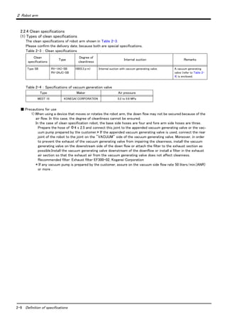
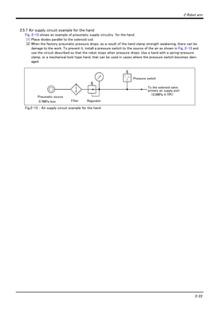
![2-29 Options
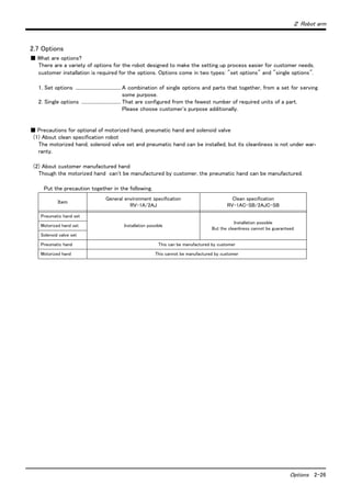
2 Robot arm
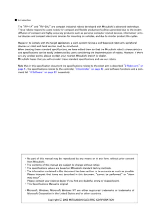
Fig.2-15 : Motorized hand outside dimensional drawing
1A-HA01
Motorized hand body
Approx. 70
(150)
Adapter
(Hexagon socket bolt)
4-M3x8
(Hexagon socket bolt)
2-M3x12
4*2-M3
Hand body
(Φ6.5x4 spot facing on the
reverse side)
[Wiring system diagram]
Connector
Curl cable
Type 1A-GHCD
Curl cable for bending
Connector
Hand curl cable
For
pneumatic
hand
Yellow
Purple
Brown
Blue
Red
Black
4-Φ3.4 hole
(90 degree division)PCD70
(From finger center)
40±10
φ11
160±10
1
2
5
6
7
8
3
4
9
6
5
4
3
1
2
DC+
DC-
Reserve
Reserve
Reserve](https://image.slidesharecdn.com/rv1a-130719143349-phpapp02/85/Rv1-a-2aj-specs-bfp-a8050k-42-320.jpg)
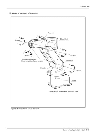
![2 Robot arm
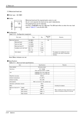
Options 2-32
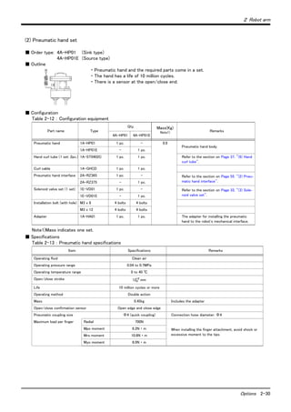
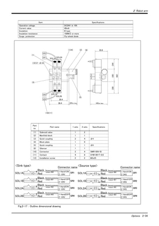
Fig.2-16 : Pneumatic hand outside dimensional drawing
Type:1A-HA01
0.1 0.2 0.3 0.4 0.5 0.6 0.7
70
60
50
30
20
10
10
20
30
40
50
40
(150)
HC1(open)
HC2(close)
For motorized hand
24.5
85
Adapter
4-M3x12
(Hexagon socket bolt)
4-M3x8
(Hexagon socket bolt)
Approx. 70 (Φ6.5x4 spot facing
on the reverse side)
4-Φ3.4 hole
(90 degree division)PCD70
Hand body
(From finger center)
[Wiring system diagram]
Connector
Yellow
Purple
Brown
Blue
Red
Black
Curl cable
Type 1A-GHCD
Curl cable for bending
Connector
Hand curl cable
Pneumatic hand body
GrippingforceN
Pneumatic pressure MPa
AttachmentmaximumlengthLcm
Indication of gripping force and maximum
length of finger attachment
HC1(open)
HC2(close)
For motorized hand
Yellow
Purple
Brown
Blue
Red
Black
<Sink type>
<Source type>
1
2
5
6
7
8
3
4
9
6
5
4
3
1
2
+24V
0V(COM)
Reserve
Reserve
Reserve
+24V(COM)
0V
Reserve
Reserve
Reserve
1
2
5
6
7
8
3
4
9
6
5
4
3
1
2
40±10
φ11
160±10](https://image.slidesharecdn.com/rv1a-130719143349-phpapp02/85/Rv1-a-2aj-specs-bfp-a8050k-45-320.jpg)
![2-35 Options
2 Robot arm
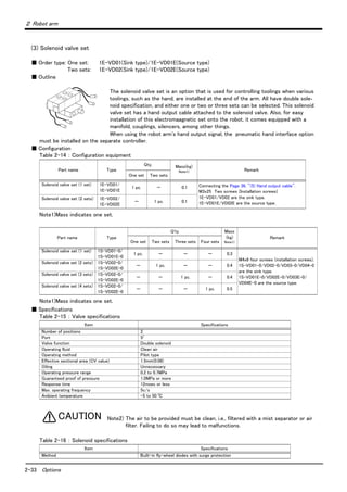
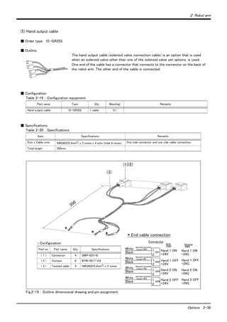
(4) Hand input cable
■ Order type: 1A-HC20
■ Outline
The hand input cable is used for customer-designed pneumatic hands.
It is necessary to use this to receive the hand's open/close confirmation signals and
grasping confirmation signals, at the controller.
One end of the cable connects to the connector for hand input signals, which is in
the wrist section of the hand. The other end of the cable connects to the sensor
inside the hand customer designed.
■ Configuration
Table 2-17 : Configuration equipment
■ Specifications
Table 2-18 : Specifications
Fig.2-18 : Outside dimensional drawing and pin assignment
[Caution] This option can be installed on clean-type, but its cleanliness is not under warranty.
Part name Type Qty. Mass(kg) Remarks
Hand input cable 1A-HC20 1 cable 0.2
Item Specifications Remarks
Size x cable core AWG#24 (0.2mm2
) × 8 cores One-sided connector, one-sided cable bridging
Total length 370mm (Including the curl section, which is 150mmlong)
φ11
60 ±10 150 ± 10 160 ±10
(1)
SMR-09V-N
1
2
3
4
5
6
7
8
9
(Yellow)
(Purple)
(Brown)
(Blue)
(Black)
(Green)
(Red)
(White)
0V
HC1
HC2
HC3
HC4
+24V
0V(COM)
Reserve
Reserve
HC1
HC2
HC3
HC4
+24V(COM)
Reserve
Reserve
Sink Source
type type
Reserve Reserve](https://image.slidesharecdn.com/rv1a-130719143349-phpapp02/85/Rv1-a-2aj-specs-bfp-a8050k-48-320.jpg)
![2-37 Options
2 Robot arm
(6) Hand curl tube
■ Order type: One set (2 pcs.) : 1E-ST0402C
Two sets (4 pcs.) : 1E-ST0404C
■ Outline
The hand curl tube is a curl tube for the pneumatic hand.
■ Configuration
Table 2-21 : Configuration equipment
■ Specifications
This option can be installed on clean-type, but its cleanliness is not under warranty.
Table 2-22 : Specifications
Fig.2-20 : Outline dimensional drawing
[Caution] This option can be installed on clean-type, but its cleanliness is not under warranty.
Part name Type Qty. Mass(kg) Remarks
Hans curl tube (One set: 2 pcs.) 1E-ST0402C 1 pc. 0.1 For single-hand: Φ4 tube, 2pcs.
Hans curl tube (Two set: 4 pcs.) 1E-ST0404C 1 pc. 0.1 For double hand: Φ4 tube, 4pcs.
Item Specifications
Material Urethane
Size Outside diameter: φ4 x Inside diameter: φ2.5
φ28(Oneset),
φ36(Twosets)
250
180
200
(Tooling side)
(Robot side)](https://image.slidesharecdn.com/rv1a-130719143349-phpapp02/85/Rv1-a-2aj-specs-bfp-a8050k-50-320.jpg)
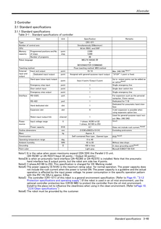
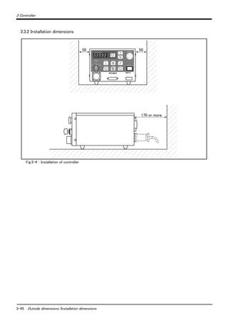
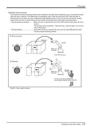
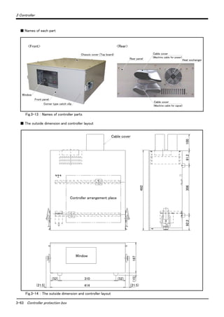
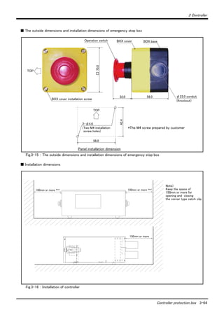
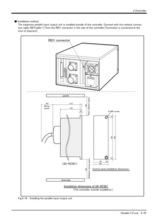
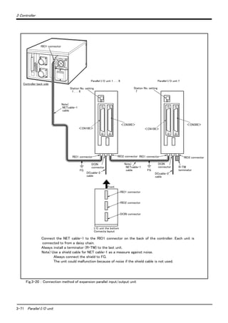
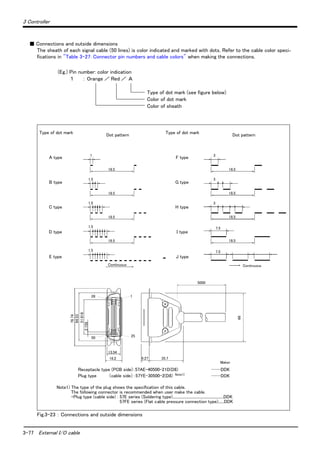
![3-43 Names of each part
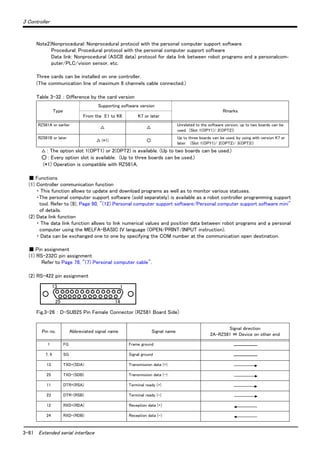
3 Controller
Note) The servo will turn OFF when the controller's [MODE] switch is changed.
Note that axes not provided with brakes could drop with their own weight.
Carry out the following operations to prevent the servo from turning OFF
whenthe [MODE] switch is changed.
The servo on status can be maintained by changing the mode with keeping pressing
lightly the deadman switch of T/B. The operating method is shown below.
■ When the mode is changed from TEACH to AUTO.
1) While holding down the deadman switch on the T/B, set the [ENABLE/DISABLE]
switch to "DISABLE".
2) While holding down the deadman switch on the T/B, set the controller [MODE]
switch to "AUTO".
3) Release the T/B deadman switch.
■ When the mode is changed from AUTO to TEACH.
1) While the [ENABLE/DISABLE] switch on the T/B is "DISABLE", hold down the
deadman switch.
2) While holding down the deadman switch on the T/B, set the controller [MODE]
switch to "TEACH".
3) While holding down the deadman switch on the T/B, set the [ENABLE/DISABLE]
switch to "ENABLE", then do the operation of T/B that you wish.
Fig.3-2 : Names of each controller part (Rear side)
1) Machine cable connector (for motor power)...........Connects to the robot arm base. (CN1 connector)
2) Machine cable connector (for motor signal)............Connects to the robot arm base. (CN2 connector)
3)Power supply terminals.
4)Fuse box.
5)External input/output signal connector.
6)Network cable connector for parallel I/O unit expansion.
7)Emergency stop switch and door switch terminals connector.
CAUTION
(6)
(7)
(5)
(1)
(2)
(4)
(3)](https://image.slidesharecdn.com/rv1a-130719143349-phpapp02/85/Rv1-a-2aj-specs-bfp-a8050k-56-320.jpg)
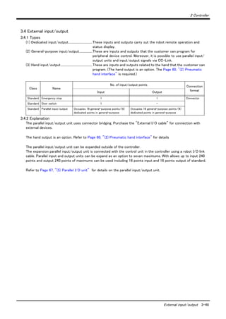
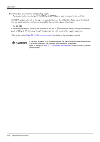
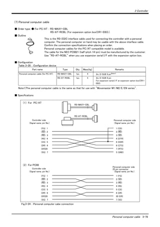
![3-49 Emergency stop input/output
3 Controller
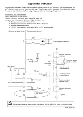
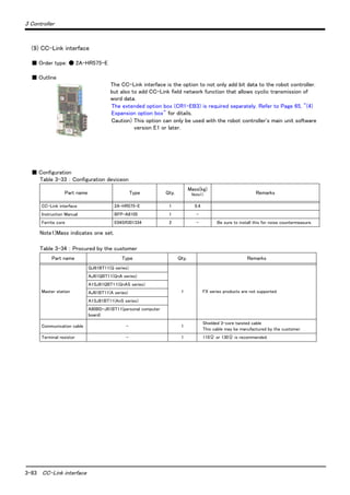
3.6 Emergency stop input/output
This signal is input from the "emergency stop input" terminal in the controller.
Table 3-3 : Dedicated input terminals in controller
3.6.1 Connection of the external emergency stop
The external emergency stop input and door switch input are short-circuited with a short cable at shipment as
shown in Fig. 3-5.
Connect the external emergency stop switch and door switch with the following procedure.
1) Prepare the "emergency stop switch" and "door switch".
2) Remove the two short pieces 1 and 2.
3) Securely connect the external emergency stop's contacts across "1)-2), and the door switch's contacts
across 3)-4)" on the terminal block.
Fig.3-5 : Connection of the external emergency stop
[Note] Refer to Page 105, "6.1.7 Examples of safety measures" together, and carry out wiring to the emergency stop.
Class Name Details
Input Emergency stop Applies the emergency stop (Single emergency line.)
Input Door switch The servo turns OFF.
Output Emergency stop This output indicates that the emergency stop input or the door switch input is turned on.
RA1
RA2
RA3
RG (24G)
RG (24G)
24V
24V
EMG.
STOP
DOOR
Switch
1
2
3
4
5
6
RA5
1
2
3
4
5
6
1)
2)
3)
4)
5)
6)
Short piece 1
Short piece 2
Emergency stop input
Door switch input
Emergency stop output
Composition of external emergency stop and door switch
System emergency
stop line
(Prepared by customer)
Example of wiring for external emergency stop and door switch
(customer-prepared wiring)
Controller rear side
Terminal block array of
external emergency stop
Wire insert
Wire fixing screw
Note1)
Maker:Phoenix Contact
Type:FRONT-MSTB2.5/6-ST-5.08
(Customer-prepared wiring) (Controller side)
Note 1) Emergency stop output opens when either one of the
emergency stop switches shown below or an input signal turns on.
・Emergency stop switch of the controller.
・Emergency stop switch or deadman switch of the T/B (option).
・External emergency stop input.
・External door input.
・The T/B mount/dismount switch is OFF
when the T/B is unconnected.](https://image.slidesharecdn.com/rv1a-130719143349-phpapp02/85/Rv1-a-2aj-specs-bfp-a8050k-62-320.jpg)
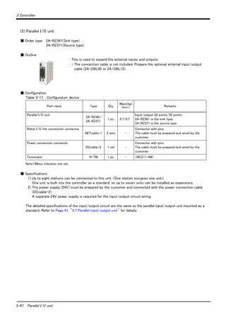
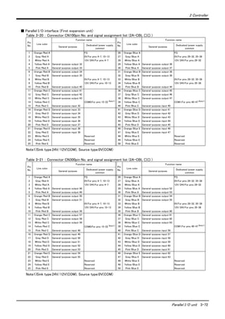
![3-51 Parallel input/output unit
3 Controller
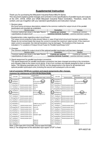
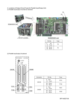
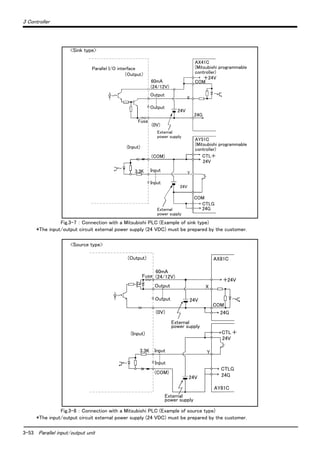
3.7 Parallel input/output unit
・ A parallel input/output card is mounted as a standard in the controller's control unit.
・ The external input/output circuit specifications are shown in Table 3-4 and Table 3-5.
・ The correspondence of the external input/output connector pin No. and the colors of the connected "external
input/output cable" wires (separate option) is as shown in Page 54, "Table 3-6"and Table 3-7. Refer to Page
76, "(6) External I/O cable" for details of external I/O cable.
・ Pin Nos. described as both general-purpose signal and dedicated signal can be shared.
・ The other dedicated input/output signals that are not assigned can be assigned to required general-purpose
input/output pins when creating the program.
・If the standard inputs and outputs are insufficient, install the parallel input/output unit connection option outside
the controller.
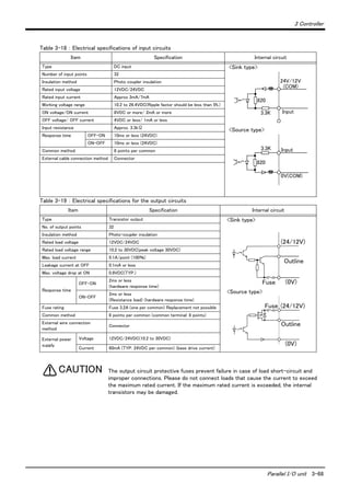
Table 3-4 : Electrical specifications of input circuit
Table 3-5 : Electrical specifications of output circuit
[Caution] When connecting the phototransistor output to the input circuit, be sure to allocate an input current of
approximately 7 mA at 24 VDC. Especially when using a photo diode and a phototransistor (sensor)
away from each other, it is recommended to verify the current that can be carried in the design stage.
Item Specifications Internal circuit
Type DC input <Sink type>
<Source type>
No. of input points 16
Insulation method Photo-coupler insulation
Rated input voltage 12VDC/24VDC
Rated input current Approx. 3mA/approx. 7mA
Working voltage range 10.2VDC to 26.4VDC(ripple rate within 5%)
ON voltage/ON current 8VDC or more/2mA or more
OFF voltage/OFF current 4VDC or less/1mA or less
Input resistance Approx. 3.3kΩ
Response time OFF-ON 10ms or less(DC24V)
ON-OFF 10ms or less(DC24V)
Common method 8 points per common
External wire connection
method
Connector
Item Specifications Internal circuit
Type Transistor output <Sink type>
<Source type>
No. of output points 16
Insulation method Photo-coupler insulation
Rated load voltage DC12V/DC24V
Rated load voltage range DC10.2 ~ 30V(peak voltage 30VDC)
Max. load current 0.1A/point (100%)
Leakage current at OFF 0.1mA or less
Max. voltage drop at ON DC0.9V(TYP.)
Response time
OFF-ON
2ms or less
(hardware response time)
ON-OFF
2ms or less
(Resistance load) (hardware response time)
Fuse rating Fuse 3.2A (one per common) Replacement not pos-
sible
Common method 8 points per common (common terminal: 8 points)
External wire connection
method
Connector
External power
supply
Voltage DC12/24V(DC10.2 ~ 30V)
Current
60mA (TYP. 24VDC per common)
(base drive current)
3.3K Input
820
24V/12V
(COM)
3.3K Input
820
0V(COM)
(24/12V)
Outline
(0V)Fuse
Fuse (24/12V)
Outline
(0V)](https://image.slidesharecdn.com/rv1a-130719143349-phpapp02/85/Rv1-a-2aj-specs-bfp-a8050k-64-320.jpg)


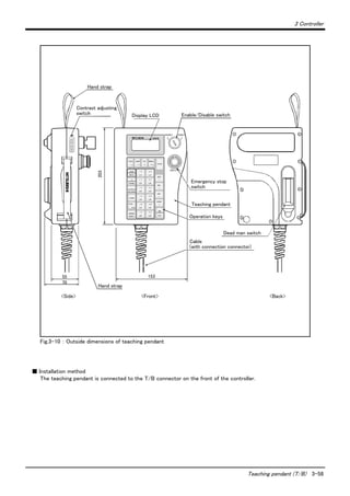
![3-57 Teaching pendant (T/B)
3 Controller
(1) Teaching pendant (T/B)
Order type: R28TB
■ Outline
This is used to create, edit and control the program, teach the operation position and
for jog feed, etc.
For safety proposes, a 3-position deadman switch is mounted.Note1)
If there are several robots, one teaching pendant can be used by connecting it to the
respective robot.
■ Configuration
Table 3-8 : Configuration device
■ Specifications
Table 3-9 : Specifications
Note2) The manual operation section of the teaching pendant has a protection method that complies with the IEC
Standards IP65 (protection type).
[Reference] IProtection against water infiltration as specified in IP65 indicates a protective structure that is
not harmfully affected when 12.5± 5% liters of water is supplied from a test device at a position
approx. 3m away in various directions and a water pressure of 30kPa at the nozzle section. The
water is filled one minute per 1m2 of test device surface area for a total of three minutes.
.
Note1) <3-position deadman switch>
In ISO/10218 (1992) and JIS-B8433 (1993), this is defined as an "enable device". These standards specify that the
robot operation using the teaching pendant is enabled only when the "enable device" is at a specified position.
With the Mitsubishi Electric industrial robot, the above "enable device" is configured of an "Enable/Disable switch"
and "Deadman switch".
The 3-position deadman switch has three statuses. The following modes are entered according to the switch state.
"Not pressed"...............................The robot does not operate. *)
"Pressed lightly"..........................The robot can be operated and teaching is possible.
"Pressed with force" .................The robot does not operate. *)
*) Operations, such as program editing and status display, other than robot operation are possible.
Safety is secured as the servo power is turned OFF simultaneously with the input of the emergency stop.
Part name Type Qty. Mass(kg) Remarks
Teaching pendant R28TB Either one pc. 2.0 Cable length is 7m. Hand strap is attached.
R28TB-15 2.3 Cable length is 15m. Hand strap is attached.
Items Specifications Remarks
Outline dimensions 153(W) x 203(H) x 70(D) (refer to outline drawing)
Body color Light gray (reference Munsell color: 0.08GY7.64/0.81)
Mass Approx. 0.8kg (only arm, excluding cable)
Connection method Connection with controller and round connector (30-pin)
Interface RS-422
Display method LCD method: 16 characters x 4 lines, LCD illumination: with backlight
Operation section 28 keys
Protection specifications IP65 Note2)](https://image.slidesharecdn.com/rv1a-130719143349-phpapp02/85/Rv1-a-2aj-specs-bfp-a8050k-70-320.jpg)
![3-59 Teaching pendant (T/B)
3 Controller
■ Key layout and main functions
Fig.3-11 : Teaching pendant key layout and main functions
R28TB
1)
6)
5)
13)
2)
14)
15)
16)
17)
10)
3)
4)
12)
11)
18)
7)
8)
9)
DISABLE
EMG.STOP
TOOL
=*/
STEP
MOVE
+
FORWD
-
BACKWD
ADD
↑
RPL
↓
DEL
←
HAND
→
INP
EXE
COND
ERROR
RESET
POS
CHAR
JOINT
( )?
XYZ
$" :
MENU
STOP
-X
(J1)
+ X
(J1)
-Y
(J2)
+ Y
(J2)
-Z
(J3)
+ Z
(J3)
-A
(J4)
+ A
(J4)
-B
(J5)
+ B
(J5)
-C
(J6)
+ C
(J6)
SVO ON
ENABLE
# % !
19)
Back
1) : Emergency stop switch...................The robot servo turns OFF and the operation stops immediately.
2) : T/B enable/disable
changeover switch............................This switch changes the T/B key operation between enable and dis-
able.
3) : LCD display panel .............................The robot status and various menus are displayed.
4) : <TOOL, JOINT, XYZ> key.............This selects the jog mode (JOINT, XYZ, 3-AXIS XYZ, CYLINDER,
TOOL).
5) : <MENU> key........................................This returns the display screen to the menu screen.
6) : <STOP> key ........................................This stops the program and decelerates the robot to a stop.
7) : <STEP/MOVE> key..........................Jog operation is carried out when this key is pressed simultaneously
with the jog operation key. This also turns the Servo ON and carries
out step jump.
8) : <( + FORWD> key............................This carries out step feed and increases the override.
9) : <( - BACKWD> key.........................This carries out step return (return along operation path) and
decreases the override.
10) : <COND> key.....................................This sets the program.
11) : <ERROR RESET> key...................This resets the error, and releases the software limit.
12) : Jog operation key...........................This operates the robot according to the jog mode. When inputting
numeric values, this inputs each numeric value.
13) : <ADD/ ↑ > key...............................This additionally registers the position data. It also moves the cursor
upward.
14) : <RPL/ ↓ > key................................It also moves the cursor downward.
15) : <DEL/ ← > key................................This deletes the position data. It also moves the cursor to the left.
16) : <HAND/ → > key............................This opens and closes the hand. It also moves the cursor to the right.
17) : <INP/EXE> key................................This inputs the program, and carries out step feed/return.
18) : <POS CHAR> key...........................This changes the edit screen, and changes between numbers and
alphabetic characters.
19) : Deadman switch..............................When the [Enable/Disable] switch "2)" is enabled, and this key is
released or pressed with force, the servo will turn OFF, and the oper-
ating robot will stop immediately.](https://image.slidesharecdn.com/rv1a-130719143349-phpapp02/85/Rv1-a-2aj-specs-bfp-a8050k-72-320.jpg)
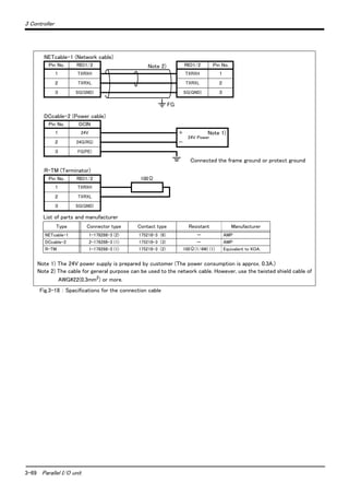
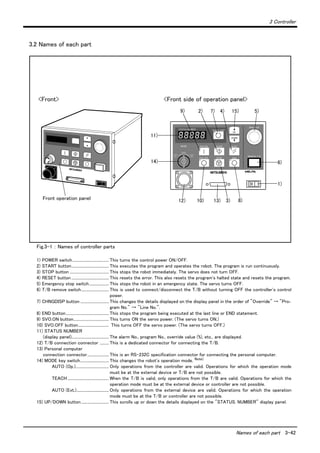
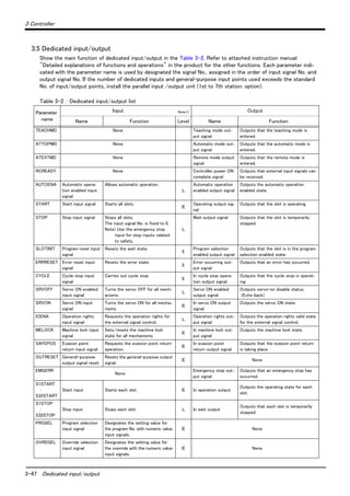
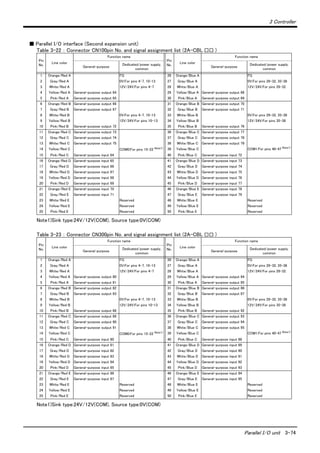
![3-73 Parallel I/O unit
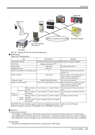
3 Controller
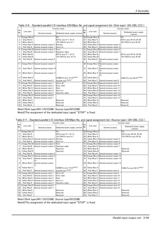
Fig.3-21 : Parallel input/output unit <2A-RZ361/2A-RZ371:First expansion> connection and pin layout
[*1] For the 1st expansion unit, set the channel No. to "1".
The channel No. of 8 to F is used for the maker test. If any value of 8 to F is set, it may
be dangerous since the robot unexpectedly moves. Don't set any value of 8 to F.
50
26
25
1
Channel No. setting
TXD
LED display
Input 32 to 47
Output 32 to 47
<CN100>
<CN300>
Input 48 to 63
Output 48 to 63
(Set channel No. to 1.)
*The 2A-RZ361/2A-RZ371 has 32 input and 32 output points unit
(Occupies one channel)
[*1]
CAUTION](https://image.slidesharecdn.com/rv1a-130719143349-phpapp02/85/Rv1-a-2aj-specs-bfp-a8050k-86-320.jpg)
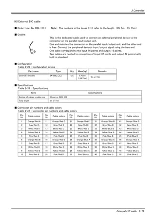
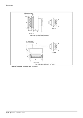
![3-75 Parallel I/O unit
3 Controller
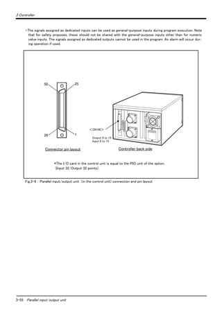
Fig.3-22 : Parallel input/output unit <2A-RZ361/2A-RZ371:Second expansion unit> connection and pin layout
[*1] For the 2nd expansion unit, set the channel No. to "2".
The channel No. of 8 to F is used for the maker test. If any value of 8 to F is set, it may
be dangerous since the robot unexpectedly moves. Don't set any value of 8 to F.
Table 3-24 lists the correspondence between the station numbers to be set and the I/O signal assignment.
Refer to this table when the third and subsequent units are used.
Table 3-24 : Station Number Settings and I/O Signal Assignment
Unit No. Station number setting CN100 CN300
1st unit 1 Input: 32 ~ 47
Output: 32 ~ 47
Input: 48 ~ 63
Output: 48 ~ 63
2nd unit 2 Input: 64 ~ 79
Output: 64 ~ 79
Input: 80 ~ 95
Output: 80 ~ 95
3rd unit 3 Input: 96 ~ 111
Output: 96 ~ 111
Input: 112 ~ 127
Output: 112 ~ 127
4th unit 4 Input: 128 ~ 143
Output: 128 ~ 143
Input: 144 ~ 159
Output: 144 ~ 159
5th unit 5 Input: 160 ~ 175
Output: 160 ~ 175
Input: 176 ~ 191
Output: 176 ~ 191
6th unit 6 Input: 192 ~ 207
Output: 192 ~ 207
Input: 208 ~ 223
Output: 208 ~ 223
7th unit 7 Input: 224 ~ 239
Output: 224 ~ 239
Input: 240 ~ 255
Output: 240 ~ 255
50
26
25
1
Channel No. setting
TXD
LED display
Input 64 to 79
Output 64 to 79
<CN100>
<CN300>
Input 80 to 95
Output 80 to 95
(Set channel No. to 2.)
*The 2A-RZ361/2A-RZ371 has 32 input and 32 output points unit
(Occupies one Channel)
[*1]
CAUTION](https://image.slidesharecdn.com/rv1a-130719143349-phpapp02/85/Rv1-a-2aj-specs-bfp-a8050k-88-320.jpg)
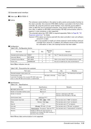

![3 Controller
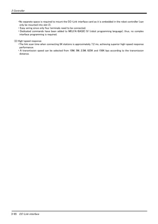
Additional axis interface 3-88
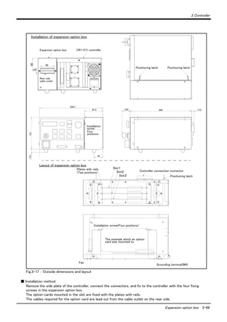
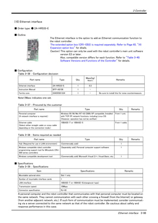
(11) Additional axis interface
■ Order type: ● 2A-RZ541-E
■ Outline
The additional axis interface is an interface, which uses the general-purpose servo
amplifier of Mitsubishi and the corresponding servomotors in order to allow the plural
above servomotors to be controlled from the robot controller.
The extended option box (CR1-EB3) is required separately. Refer to Page 65, "(4)
Expansion option box" for ditails.
Caution) Additional axis interface can be used with a robot controller software
version of G9 or later.
Servo systems that can be used with the additional axis interface are shown in Table 3-41.
Table 3-41 : Applicable servo systems
■ Configuration
Table 3-42 : Configuration deviceon
The products necessary in addition to the additional axis interface are listed in Table 3-43.
For these main products, refer to "Instruction Manual for Servo Amplifier and Servomotor".
Table 3-43 : Procured by the customer
Servo amplifier name Type
Mass(kg)
Note1)
Note1)Mass indicates one set.
Maker name
MELSERVO-J2-Super series Note2)
Note2) The J2-Super Series servo amplifiers, use the servo amplifiers with software version of B0 or later.
MR-J2S- □ B (ABS must be designated.) 0.3 Mitsubishi Electric
Part name Type Qty. Remarks
Additional interface 2A-RZ541-E 1
Instruction Manual BFP-A8107 1
Ferrite core E04SR301334 2 Be sure to install this for noise countermeasure.
Part name Type Qty. Remarks
Servo amplifier, servomotor, option, peripheral
device
Refer to "Instruction Manual for Servo Amplifier and
Servomotor".
-
Battery (for absolute position detection system) MR-BAT or A6BAT Amplifier
quantity
Setup software
(For setup the parameter of servo amplifier and
the graph indication, etc. )
MRZJW3-SETUP131 if the MELSERVO-J2-Super is used.
MRZJW3-SETUP41 or later if the MELSERVO-J2-B is used.
1
Communication cable
(Communication cable between personal
computer and servo amplifier for setup software)
MR-CPCATCBL3M 1
Bus cable between controller and amplifier
(Exclusive cable for communication between
controller and servo amplifier)
MR-J2HBUS □ M
(Cable length in : 0.5, 1 and 5 [m])
Note) The MR-J2HBUS □ M-A can't be used, caution.
1
Terminator MR-A-TM 1
Bus cable between amplifier and amplifier
(Exclusive cable for communication between
servo amplifier and servo amplifier)
MR-J2HBUS □ M
(Cable length in : 0.5, 1 and 5 [m])
Amplifier
quantity-1](https://image.slidesharecdn.com/rv1a-130719143349-phpapp02/85/Rv1-a-2aj-specs-bfp-a8050k-101-320.jpg)
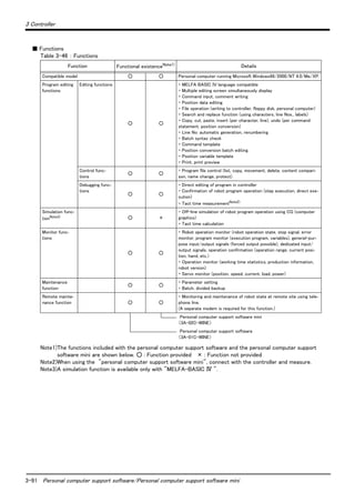
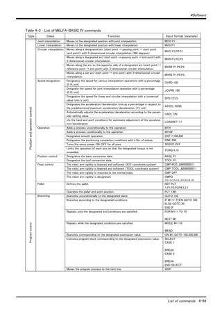
![4-93 List of commands
4Software
4 Software
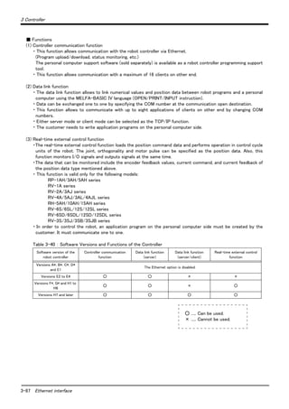
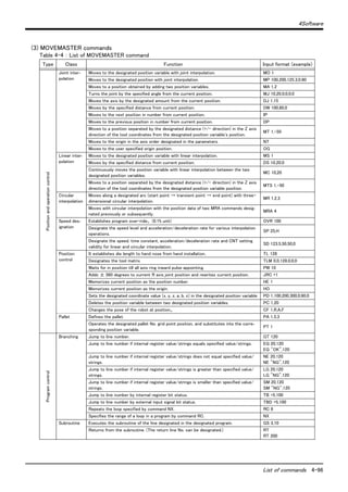
4.1 List of commands
The robot language to use can choose "MELFA-BASIC Ⅳ " (default setting) or "MOVEMASTER language
(MOVEMASTER commands)" by changing the parameter.
Use of "MELFA-BASIC IV" is recommended to effectively use this controller's functions.
The available new functions in MELFA-BASIC IV are given in Table 4-1.
Table 4-1 : The available new functions in MELFA-BASIC IV
(1) The procedure of robot language selection
Table 4-2 : Robot language parameter
Note 1) "MELFA-BASIC Ⅳ " is default setting.
Note 2) Refer to the separate manual "Explanation of MOVEMASTER COMMANDS"(BFP-A8056) for details of
"MOVEMASTER COMMAND"
(2) MELFA-BASIC Ⅳ commands
Class Command example Function
Robot Status Variable P_TOOL keep current tool length
M_SPD keep current speed (linear/circular interpolation)
Built-in functions ABS Produces the absolute value
VAL Converts a character string into a numeric value
ATN Calculates the arc tangent
STR$ Converts the numeric expression value into a decimal character string
ZONE Check current position area
Operation function P1=P1*P2 Relative calculation of position data
M1=M1*M2 Multiplication of numerical variable
P1.X=10 Operation of the position element data
Conditional branching SELECT CASE More than one condition branch
ON GOSUB Condition branch by the value
WHILE WEND Repeat with condition
Optimum acceleration/
deceleration control
LOADSET Load condition setting
OADL valid/invalid setting for the optimum acceleration/deceleration
Float control
(compliance in the XYZ
coordinate system)
CMP POS Compliance control
CMPG Force control
Parallel execution
(Multitask)
XRUN, XSTP, XRST,
XLOAD, XCLR
Parallel executions of another task, the stops, the resets the clear, and, the loads
Conveyor trucking
[Special specification]
TRKON, TRKOFF Valid/invalid of the trucking
TRBASE Setting the base coordinate for the trucking
Impact detection COLCHK Set to enable/disable the impact detection.
COLLVL Set the detection level of the impact detection.
Singular point passage MVS P1 TYPE 0,2 Pass a singular point using linear interpolation.
Parameter
Parameter
name
No. of arrays
No. of characters
Details explanation
Factory
setting
Robot language RLNG Integer 1
Select the robot language to use
1 : MELFA-BASIC Ⅳ
0 : MOVEMASTER COMMAND
1](https://image.slidesharecdn.com/rv1a-130719143349-phpapp02/85/Rv1-a-2aj-specs-bfp-a8050k-106-320.jpg)
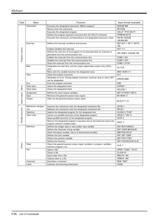
![4Software
List of parameters 4-98
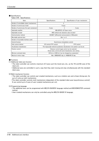
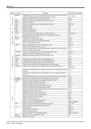
4.2 List of parameters
(1) List of parameters
show the main parameter in the Table 4-5.
Table 4-5 : List of parameters
Parameter Details
Standard tool coordinates. MEXTL Set the default value for the tool data.
Unit: mm or deg.
Standard base coordinates MEXBS Set the relation of the world coordinate system and robot coordinate system.
Unit: mm or deg.
XYZ operation range MEPAR Designate the overrun limit value for the world coordinate system.
JOINT operation range MEJAR Set the overrun limit value for each joint axis.
Free plane limit This is the overrun limit set with the free plane.
Create a plane with the three coordinates x1, y1, z1 to x3, y3, z3, and set the outer side of
the plane as the outside operation range (error). The following three types of parameters are
used.
SFC1P
:
SFC8P
Eight types of free plane limits can be set in SFC1P to SFC8P.
There are nine elements, set in the order of x1, y1, z1, x2, y2, z2, x3, y3, z3.
SFC1ME
:
SFC8ME
Designate which mechanism to use eight types of set free plane limits.
The mechanism No. to use is set with 1 to 8.
SFC1AT
:
SFC8AT
Set the validity of the eight types of set free plane limits.
(Valid 1/Valid 2/invalid = 1/-1/0)
User-defined area An area (cube) defined with two XYZ coordinate points can be designated and that area set
as the outside operation range. Furthermore, a signal can be output when the axis enters
that area. Up to eight types of area can be designated.
AREA1P1
:
AREA8P1
Designated the 1st point of the area.
There are eight elements, set in the order of x, y, z, a, b, c, L1, L2.
(L1 and L2 are the additional axes.)
AREA1P2
:
AREA8P2
Designated the 2nd point of the area.
There are eight elements, set in the order of x, y, z, a, b, c, L1, L2.
(L1 and L2 are the additional axes.)
AREA1ME
:
AREA8ME
Designate which mechanism to use the eight types of set area.
The mechanism No. to use is set with 1 to 8
AREA1AT
:
AREA8AT
Designate the area check type.
(Invalid/zone/interference = 0/1/2)
Zone: The dedicated output signal USRAREA turns ON.
Interference: An error occurs..
Automatic return setting RETPATH Set to restart the program after returning to the interrupt position when resuming operation
after an interruption.
Buzzer ON/OFF BZR Designate whether to the turn buzzer ON or OFF.
Jog setting JOGJSP Designate the joint jog and step operation speed.
(Set dimension H/L amount, max. override.)
JOGPSP Designate the linear jog and step operation speed.
(Set dimension H/L amount, max. override.)
Jog speed limit value JOGSPMX Limit the operation speed during the teaching mode. Max. 250[mm/s]](https://image.slidesharecdn.com/rv1a-130719143349-phpapp02/85/Rv1-a-2aj-specs-bfp-a8050k-111-320.jpg)
![5-103 Safety
6Safety
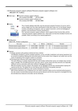
6 Safety
6.1 Safety
Measures to be taken regarding safety of the industrial robot are specified in the "Labor Safety and Sanitation
Rules". Always follow these rules when using the robot to ensure safety.
6.1.1 Self-diagnosis stop functions
This robot has the self-diagnosis stop functions shown in Table 6-1 and the stop functions shown in Table 6-2
for safe use.
Table 6-1 : Self-diagnosis stop functions
Table 6-2 : List of stop functions
6.1.2 External input/output signals that can be used for safety protection measures
Table 6-3 : External input/output signals that can be used for safety protection measures
[Caution] The external emergency stop input is prepared as a b contact for safety proposes. Thus, if the emer-
gency stop input circuit is opened when the robot is started up, the robot will not operate. Refer to
"Fig. 6-1 Example of safety measures"for details.
No. Function Details Remarks
1 Overload protection func-
tion
Activates when the total servo current time exceeds
the specified value.
The drive circuit is shut off. The robot stops, and
an alarm displays.
2 Overcurrent diagnosis
function
Activates when an overcurrent flows to the motor
circuit.
The drive circuit is shut off. The robot stops, and
an alarm displays.
3 Encoder disconnection
diagnosis function
Activates when the encoder cable is disconnected. The drive circuit is shut off. The robot stops, and
an alarm displays.
4 Deflection over diagnosis
function
Activates when an error occurs between the com-
mand value and actual position, and the error
exceeds the specified amount.
The drive circuit is shut off. The robot stops, and
an alarm displays.
5 AC power voltage drop
diagnosis function
Activates when the AC power voltage drops below
the specified value.
The drive circuit is shut off. The robot stops, and
an alarm displays.
6 CPU error detection func-
tion
Activates when an error occurs in the CPU. The drive circuit is shut off. The robot stops, and
an alarm displays.
7 Overrun
prevention
function
Software limit
detection
This is the limit provided by the software to enable
operation only in the operation range.
The drive circuit is shut off. The robot stops, and
an alarm displays.
Mechanical
stopper
This is the mechanical stopper provided outside the
software.
The robot mechanically stops, and function 1 or 2
activates.
Stop
function
Operation
panel
Teaching
pendant
External
input
Details
Emergency
stop ◯ ◯ ◯
This is the stop with the highest degree of emergency. The servo power is shut off,
and the mechanical brakes (all axes) activate to stop the robot.
To recover, reset the alarm, and turn the servo ON with the servo ON command.
Stop ◯ ◯ ◯
This is a stop operation with a high degree of emergency. The robot immediately
decelerates and stops.
Note that the servo power is not shut off. Use this when using the collision evasion
sensor, etc.
Signal Command Functions Usage method
Input
External emer-
gency stop
(Input signal) This servo power is shut off, and the robot
stops immediately.
Externally installed emergency stop switch.
Door switch on safety protection fence.
Stopping at high-level error occurrence.
Stop STOP The program execution is stopped, and the
robot stops. The servo power is not shut off.
The robot is stopped when a peripheral device
fault occurs. The servo power is not shut off.
Servo OFF SRVOFF The servo power can be shut off. The robot is stopped when a peripheral device
fault occurs. The servo power is not shut off.
Automatic opera-
tion enable
AUTOENA Disables automatic operation when inactive. Door switch on safety protection fence
Output
In servo ON SRVON The servo power ON/OFF state is output. The servo power ON/OFF state is shown and
alerted with the display lamps.
Waiting STOP Outputs that the robot is temporarily stopped. The temporary stop state is shown and alerted
with the display lamps.
In alarm ERRRESET Outputs when an alarm occurs in the robot. The alarm state is shown and alerted with the dis-
play lamps.](https://image.slidesharecdn.com/rv1a-130719143349-phpapp02/85/Rv1-a-2aj-specs-bfp-a8050k-116-320.jpg)
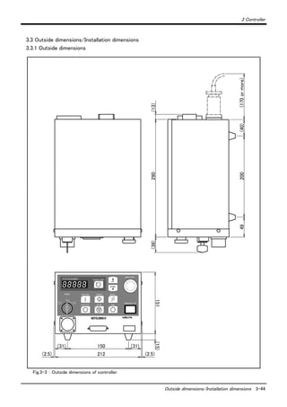
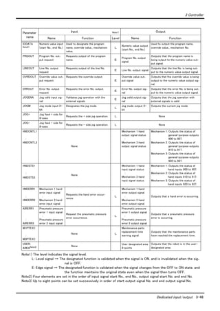
![5-105 Safety
6Safety
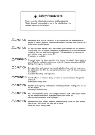
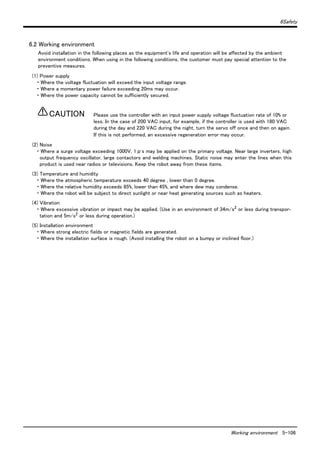
6.1.7 Examples of safety measures
Emergency stop input circuits are prepared on the user wiring terminal block of the controller. Create a circuit as
shown below for safety measures
.
Fig.6-1 : Example of safety measures
(1) Install a limit switch on the safety fence's door. With a constantly open contact (a contact), wire to the door
switch input terminal so that the switch turns ON (is conducted) when the door is closed, and turns OFF (is
opened) when the door is open.
(2) Use a manual-return type b-contact for the emergency stop button.
(3) Classify the faults into minor faults (faults that are easily restored and that do not have a great effect) and
major faults (faults that cause the entire system to stop immediately, and that require care in restoration),
and wire accordingly.
[Caution] The emergency stop input(terminal block) on the user wiring in the controller can be used for safety
measures as shown in Fig. 6-1. Note that there are limits to the No. of switch contacts, capacity and
cable length, so refer to the following and install.
・ Switch contact capacity........................Use a contact that operates with a switch contact capacity of
approx. 1mA to 100mA/24V.
・ Cable length................................................The length of the wire between the switch and terminal block
must be max. 15m or less.
・ Emergency stop output capacity.......Set it within 300 mA/24 VDC.
Connecting an external device outside of the above range will
cause a controller failure.
[Reference] The specifications of the RA1 and RA2 coil shown in Fig. 6-1 are as follow.
・ Rated voltage ............................DC24V ± 10%
・ Rated excitation current ......12.5mA ± 10% (at25 deg.)
* Note that these specifications are subject to change without prior notice for modification purposes.
1
2
3
4
5
6
RA1
24V
MC1
RA3
+
MC1
S/W-EMG
RA1
RA2
RA3
RA2
RA2
RA4
RA1
MC1
<Customer-prepared wiring> <Robot controller system>
To servo main circuit power
External emergency
stop input
Teaching pendant
deadman switch
Operation panel
emergency stop
Teaching pendant
emergency stop
Teaching pendant
deadman switch
Software emergency
stop
External emergency
stop output
T/B remove
switch
Door switch
input
External emergency
stop
Door switch
[Caution] Some information has been omitted for explanation proposes, so some parts may differ.](https://image.slidesharecdn.com/rv1a-130719143349-phpapp02/85/Rv1-a-2aj-specs-bfp-a8050k-118-320.jpg)


The document provides specifications for the Mitsubishi RV-1A and RV-2AJ series industrial robots. It describes the standard structural equipment that makes up the robots, including the robot arm and controller. It also covers optional equipment, maintenance parts, and the contents and specifications of the robot arm and controller components. The document is intended to help users understand the robots' characteristics and specifications.