Download to read offline
![Ruchi Aggarwal et al Int. Journal of Engineering Research and Applications www.ijera.com
ISSN : 2248-9622, Vol. 4, Issue 5( Version 2), May 2014, pp.102-105
www.ijera.com 102 | P a g e
Voltage Stability Improvement of Grid Connected Wind Driven
Induction Generator Using Svc
Ruchi Aggarwal*1
, Sanjeev Kumar*2
Student*1
Asst .Professor*2
Electrical Engg.Department, Mullana University (MMU), Ambala
Abstract
Voltage stability is one of the major problem associated with wind power generating system which may be due
to fluctuating nature of wind, heavy load, fault occurrence or insufficient reactive power supply. The wind
power generating system most commonly employed with squirrel cage induction generator(SCIG) that needs the
support of an external device such as capacitor bank, FACTS devices etc. to support reactive power in order to
remain connected with the grid during voltage dips. The voltage stability of a wind driven induction generator
can be improved by using FACTS devices such as SVC, STATCOM.In this paper svc is used for voltage
stability improvement.
Keywords— SVC, squirrel cage induction generator, wind turbine,
I. INTRODUCTION
In recent years, wind resource is a kind of
renewable energy and becomes more and more
important in many countries.Wind power has its own
characteristics, such as discreteness, randomness, and
uncontrollability.With the increase of power capacity
of future wind farms in power system, the study of
how big integrated wind farms affect power system
operation becomes quite important.For this reason,
and in order to investigate the effects of wind farms
on the grid, adequate models must be used.Voltage
instability problems and collapse typically occur on
power system that is not able to meet demand of
reactive power, for considering heavy loads and fault
conditions.When wind farms are connected to a weak
network, the voltage stability is one of the most
important factors that affect wind farm’s stable
operation. The wind turbines have to be able to
continue uninterrupted operation under transient
voltage conditions to be in accordance with the grid
codes. An induction generator connected with a wind
turbine to generate electricity is sink of reactive
power. Different solutions are found to support the
transient behavior of squirrell cage induction
generators in case of changes in the grid voltage.
Mechanically switched capacitors, SVC,
Synchronous Condensers and Voltage Source Static
Var Compensator such as the STATCOM can be
used to regulate voltage as shunt compensator to
improve the grid interface of directly
connected asynchronous wind generators. The
voltage profile is main issue when considering stable
operation of wind farm In order to maintain stable
operation and avoid over-speed of the induction
generators, some control strategies which use FACTS
devices are presented to improve stability margin.
FACT devices are based on electronic power
converters and they provide the ability to make quick
adjustments and to control the electrical system.
FACTS devices can be connected in series, in parallel,
or in a combination of both.Applied to the electrical
networks, the Flexible AC Transmission System
(FACTS) devices allow an effective dynamic state as
well as a static state of the voltage control in the
power transmission and distribution as well as the
power quality control, by implementation of the
power electronic devices,such as Static Var
Compensator (SVC) and static synchronous
compensator(STATCOM).Unlike the fixed capacitor
banks, a static var compensator(SVC) can have better
control of the voltage profile at steady state and
improve the ride-through capability of the wind
turbine generators during disturbances[8].Shunt
FACTS devices play an important role in reactive
power flow in the power network. SVC will damp
out the oscillations and improves the overall system
stability.The system operating conditions change
considerably during disturbances.So the FACTS
devices are the most suitable source to support
reactive power within reach.These devices not only
provide continuously variable susceptances but also
ability to react fast[2].
II. VOLTAGE STABILITY
Voltage Stability is defined as the ability of
power system to maintain steady voltages at all buses
in the system after being subjected to a disturbance
from a given initial operating condition.Voltage
stability is a problem in power networks, which are
heavily load, faulted, or with insufficient reactive
power supply. The main reason for voltage instability
is the increased of load, for that reason, voltage
RESEARCH ARTICLE OPEN ACCESS](https://image.slidesharecdn.com/q4502102105-140716024657-phpapp01/85/Q4502102105-1-320.jpg)
![Ruchi Aggarwal et al Int. Journal of Engineering Research and Applications www.ijera.com
ISSN : 2248-9622, Vol. 4, Issue 5( Version 2), May 2014, pp.102-105
www.ijera.com 102 | P a g e
Voltage Stability Improvement of Grid Connected Wind Driven
Induction Generator Using Svc
Ruchi Aggarwal*1
, Sanjeev Kumar*2
Student*1
Asst .Professor*2
Electrical Engg.Department, Mullana University (MMU), Ambala
Abstract
Voltage stability is one of the major problem associated with wind power generating system which may be due
to fluctuating nature of wind, heavy load, fault occurrence or insufficient reactive power supply. The wind
power generating system most commonly employed with squirrel cage induction generator(SCIG) that needs the
support of an external device such as capacitor bank, FACTS devices etc. to support reactive power in order to
remain connected with the grid during voltage dips. The voltage stability of a wind driven induction generator
can be improved by using FACTS devices such as SVC, STATCOM.In this paper svc is used for voltage
stability improvement.
Keywords— SVC, squirrel cage induction generator, wind turbine,
I. INTRODUCTION
In recent years, wind resource is a kind of
renewable energy and becomes more and more
important in many countries.Wind power has its own
characteristics, such as discreteness, randomness, and
uncontrollability.With the increase of power capacity
of future wind farms in power system, the study of
how big integrated wind farms affect power system
operation becomes quite important.For this reason,
and in order to investigate the effects of wind farms
on the grid, adequate models must be used.Voltage
instability problems and collapse typically occur on
power system that is not able to meet demand of
reactive power, for considering heavy loads and fault
conditions.When wind farms are connected to a weak
network, the voltage stability is one of the most
important factors that affect wind farm’s stable
operation. The wind turbines have to be able to
continue uninterrupted operation under transient
voltage conditions to be in accordance with the grid
codes. An induction generator connected with a wind
turbine to generate electricity is sink of reactive
power. Different solutions are found to support the
transient behavior of squirrell cage induction
generators in case of changes in the grid voltage.
Mechanically switched capacitors, SVC,
Synchronous Condensers and Voltage Source Static
Var Compensator such as the STATCOM can be
used to regulate voltage as shunt compensator to
improve the grid interface of directly
connected asynchronous wind generators. The
voltage profile is main issue when considering stable
operation of wind farm In order to maintain stable
operation and avoid over-speed of the induction
generators, some control strategies which use FACTS
devices are presented to improve stability margin.
FACT devices are based on electronic power
converters and they provide the ability to make quick
adjustments and to control the electrical system.
FACTS devices can be connected in series, in parallel,
or in a combination of both.Applied to the electrical
networks, the Flexible AC Transmission System
(FACTS) devices allow an effective dynamic state as
well as a static state of the voltage control in the
power transmission and distribution as well as the
power quality control, by implementation of the
power electronic devices,such as Static Var
Compensator (SVC) and static synchronous
compensator(STATCOM).Unlike the fixed capacitor
banks, a static var compensator(SVC) can have better
control of the voltage profile at steady state and
improve the ride-through capability of the wind
turbine generators during disturbances[8].Shunt
FACTS devices play an important role in reactive
power flow in the power network. SVC will damp
out the oscillations and improves the overall system
stability.The system operating conditions change
considerably during disturbances.So the FACTS
devices are the most suitable source to support
reactive power within reach.These devices not only
provide continuously variable susceptances but also
ability to react fast[2].
II. VOLTAGE STABILITY
Voltage Stability is defined as the ability of
power system to maintain steady voltages at all buses
in the system after being subjected to a disturbance
from a given initial operating condition.Voltage
stability is a problem in power networks, which are
heavily load, faulted, or with insufficient reactive
power supply. The main reason for voltage instability
is the increased of load, for that reason, voltage
RESEARCH ARTICLE OPEN ACCESS](https://image.slidesharecdn.com/q4502102105-140716024657-phpapp01/75/Q4502102105-1-2048.jpg)
![Ruchi Aggarwal et al Int. Journal of Engineering Research and Applications www.ijera.com
ISSN : 2248-9622, Vol. 4, Issue 5( Version 2), May 2014, pp.102-105
www.ijera.com 105 | P a g e
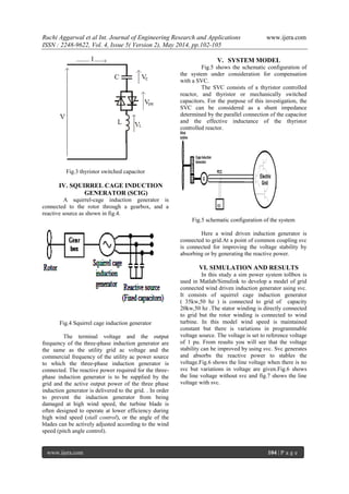
Fig 6 line voltage without svc
Fig.7 line voltage with svc
VII. CONCLUSION
From the simulation results of SVC it is
found that SVC has a significant contribution to the
voltage stability of wind driven induction
generator..When the wind speed changes the wind
turbine become disconnected.This situation is not
allowable any more, due to the increasing wind
power capacity in the power networks. The inclusion
of SVC in fixed speed wind turbine improves voltage
stability and prevents the disconnection of this
WECS technology.,SVC maintain the terminal
voltage and ensure the system running continuously.
REFERENCES
[1] Avneesh kumar Vishwakarma,Dhaneshwari
Sahu, “Efficient Voltage Regulation In
Three Phase A.C Transmisssion Lines Using
Static Var Compensator”.International
General Of Advanced Research In
Electrical,Electronics And Instrumentation
Engg.vol.2,Issue 5,May 2013.
[2] Murari Lal Azad,Vikas Kumar, “Improving
Voltage Of Grid Connected To Wind Farm
Using Static Var Compensator”,MIT
International General Of Electrical And
Instrumentation
Engg.Vol.2,No.1,Jan.2012,ISSN 2230-7656
[3] Dr.Tarlokhan Kaur,Sandeep Kakran,
“Transient Stability Improvement Of Long
Transmission Line Using
SVC”,International General Of Advanced
Research In Electrical,Electronics And
Instrumentation Engg.Vol.1,Issue 4,October
2012,ISSN-2278- 8875
[4] Mrata Molinas, Tore Undeland, “Low
Voltage Ride Through Of Wind Farm With
Cage Generators: STATCOM Versus SVC”,
IEEE Transactions On Power Electronics,
Vol.23, No.3 May 2008.
[5] Narain G. Hingorani, Laszlo Gyugyi,
“Understanding FACTS”,, ISBN 0-7803-
3455.](https://image.slidesharecdn.com/q4502102105-140716024657-phpapp01/85/Q4502102105-4-320.jpg)

1) The document discusses using an SVC (Static Var Compensator) to improve the voltage stability of a grid-connected wind-driven induction generator. 2) An SVC can generate or absorb reactive power to regulate voltage and improve stability. It contains thyristor-controlled reactors and thyristor-switched capacitors to dynamically control reactive power. 3) Simulation results show that an SVC is able to maintain terminal voltage and allow continuous operation when the grid voltage varies, improving stability compared to without an SVC.