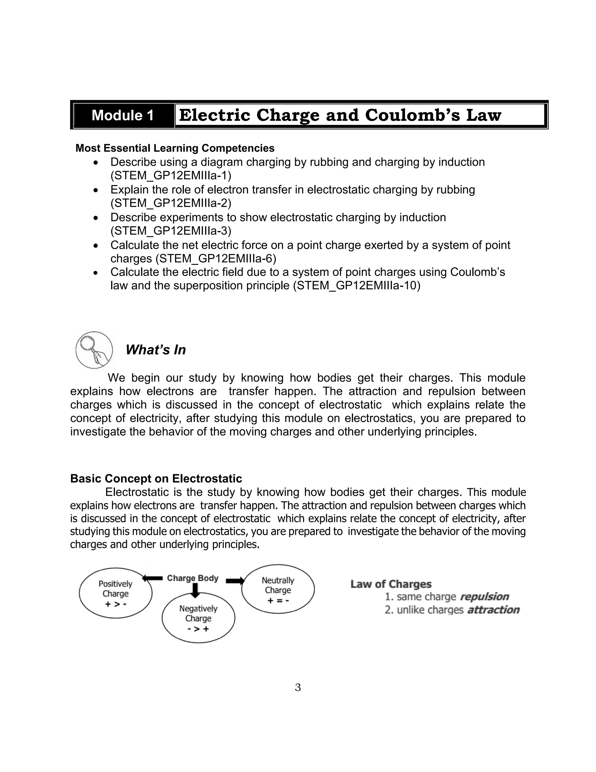
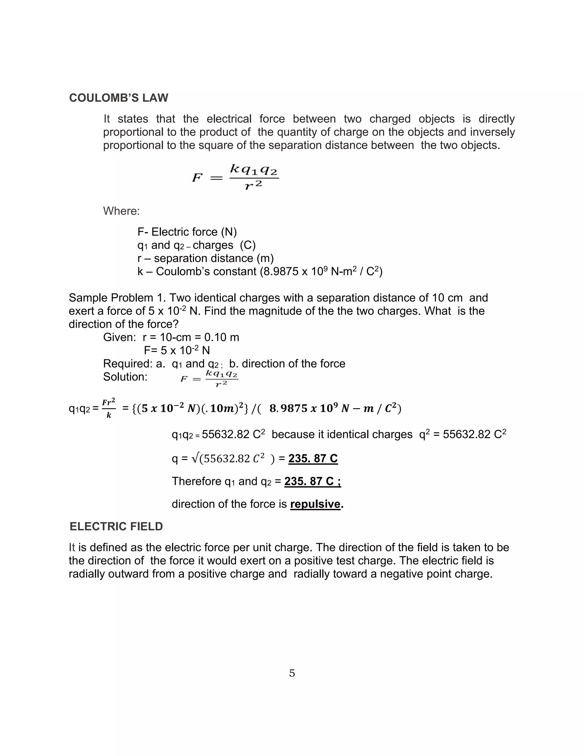
1
General Physics 2
Quarter 3: Module 1-4
12
2
DEVELOPMENT TEAM OF THE MODULE
WRITERS: MARJORIE A. NARIZ, Master Teacher I
MARIEL BARAGENIO, Teacher III
REX S. LAPID, Teacher III
MARHOUF JAY KUSAIN, Teacher I
CONSOLIDATOR: JOVELLANO V. ONTOG, Teacher III
LANGUAGE EDITOR: EMMANUEL B. DELA PEÑA, Teacher I
CONTENT LOUISE A. FERRER, Master Teacher I
VALIDATORS: MARJORIE A. NARIZ, Master Teacher I
MARY ANN M. GUEVARRA, Teacher III
LEILANI E. BRIZA, Teacher I
COVER PAGE AIRA MARI CON M. AUSTERO
ILLUSTRATOR:
TEAM LEADER: DR. RAQUEL M. AUSTERO
Education Program Supervisor
Republic of the Philippines
Department of Education
3
Module 1 Electric Charge and Coulomb’s Law
Most Essential Learning Competencies
• Describe using a diagram charging by rubbing and charging by induction
(STEM_GP12EMIIIa-1)
• Explain the role of electron transfer in electrostatic charging by rubbing
(STEM_GP12EMIIIa-2)
• Describe experiments to show electrostatic charging by induction
(STEM_GP12EMIIIa-3)
• Calculate the net electric force on a point charge exerted by a system of point
charges (STEM_GP12EMIIIa-6)
• Calculate the electric field due to a system of point charges using Coulomb’s
law and the superposition principle (STEM_GP12EMIIIa-10)
What’s In
We begin our study by knowing how bodies get their charges. This module
explains how electrons are transfer happen. The attraction and repulsion between
charges which is discussed in the concept of electrostatic which explains relate the
concept of electricity, after studying this module on electrostatics, you are prepared to
investigate the behavior of the moving charges and other underlying principles.
Basic Concept on Electrostatic
Electrostatic is the study by knowing how bodies get their charges. This module
explains how electrons are transfer happen. The attraction and repulsion between charges which
is discussed in the concept of electrostatic which explains relate the concept of electricity, after
studying this module on electrostatics, you are prepared to investigate the behavior of the moving
charges and other underlying principles.
4
Concept of Charging a Body
A. Charging by Rubbing/Friction
• Rubbing two different materials together, a process known as charging by friction
(AKA charging by rubbing), is the simplest way to give something a charge. This
is what you do every time you drag your feet along a carpet so you can reach out
and zap someone's ear. Your feet in socks and the carpet are doing charging by
friction.
• Since the two objects are made of different materials, their atoms will hold onto
their electrons with different strengths.
• As they pass over each other the electrons with weaker bonds are “ripped” off one
material and collect on the other material.
https://quizlet.com/303837656/41-charging-by-friction-flash-cards/
B. Charging by Induction
The charging by conduction process involves touching of a charged particle to a conductive
material. This way, the charges are transferred from the charged material to the conductor.
This method is useful for charging conductors.
https://www.physicsclassroom.com/class/estatics/Lesson-2/Charging-by-Induction
Figure 1. Two metal sphere are
mounted on insulating stand.
Figure 2. The presence of a - charge
induces electron e- to move from sphere A
to B. The two sphere system is polarized.
Figure 3. Sphere B is separated from
sphere A using the insulated stand. The two
sphere has opposite charges.
Figure 4. The excess charge distributes
itself uniformly ever the surface of the
sphere.
5
COULOMB’S LAW
It states that the electrical force between two charged objects is directly
proportional to the product of the quantity of charge on the objects and inversely
proportional to the square of the separation distance between the two objects.
Where:
F- Electric force (N)
q1 and q2 – charges (C)
r – separation distance (m)
k – Coulomb’s constant (8.9875 x 10⁹ N-m2 / C2)
Sample Problem 1. Two identical charges with a separation distance of 10 cm and
exert a force of 5 x 10⁻² N. Find the magnitude of the the two charges. What is the
direction of the force?
Given: r = 10-cm = 0.10 m
F= 5 x 10⁻² N
Required: a. q1 and q2 ; b. direction of the force
Solution:
q1q2 =
𝑭𝒓𝟐
𝒌
= {(𝟓 𝒙 𝟏𝟎−𝟐
𝑵)(. 𝟏𝟎𝒎)𝟐
} /( 𝟖. 𝟗𝟖𝟕𝟓 𝒙 𝟏𝟎𝟗
𝑵 − 𝒎 / 𝑪𝟐
)
q1q2 = 55632.82 C2 because it identical charges q2 = 55632.82 C2
q = √(55632.82 𝐶2
) = 235. 87 C
Therefore q1 and q2 = 235. 87 C ;
direction of the force is repulsive.
ELECTRIC FIELD
It is defined as the electric force per unit charge. The direction of the field is taken to be
the direction of the force it would exert on a positive test charge. The electric field is
radially outward from a positive charge and radially toward a negative point charge.
6
https://rb.gy/pketnk
Electric Field, E =
𝐹𝑜𝑟𝑐𝑒
𝐸𝑙𝑒𝑐𝑡𝑟𝑖𝑐 𝑐ℎ𝑎𝑟𝑔𝑒
=
𝐹
𝑞𝑜
; E=kq/r2
Where:
F- Force (N)
qo- electric charge (C)
r – distance (m)
Sample Problem 2. What will be the relationship between the electric field and
force; electricfield and charge.
E=F/q let E = F assume the value for F as 0 1 2 3 4, therefore the value of E
depends on F. An increase in value in F, an increase also with the value of E. Same
thing happen when the value of F decreases, E value also decreases. Therefore E
directly proiportional with F.
Sample Problem 3. What is the electric field due to a point charge of 1.5 x 10⁻⁶ C at
a distance of 2 meter away from it?
Given: q = 1.5 x 10⁻⁶ C; r = 2 m
Required: E
Solution: E = kq/r2 = {(8.9875 x 10⁹ N-m / C2)( 1.5 x 10⁻⁶ C)} / (2m)2
E= 3, 370.31 N/C
For the relationshuip between the E and q, use E=
1
q
, Let uis see what happen to
the value of E when q equals to 1 2 3 4. As the value of q increases the value of E
decreases. Therefore, E is inversely proportiuonal to q.
7
What’s More
Activity 1: Lose Electron or Hold Electron.
Directions: From the given situation, identify which materials tends to lose electron and
hold electron.
Situation 1. Pete is rubbing copper rod with the fur. Which material more:
A. Positive: _____________________
B. Negative: _____________________
Reasons:_________________________________________________________
______________________________________________________________________
Situation 2. Given the following material for changing by rubbing: glass, wool, fur, and
brass. Describe the tendency of the material in:
A. losing electron;
B. hold electron.
Activity 2: Let’s Induct the Electron.
Directions: Two neutral sphere is place together as ilustrated in the figure below. You
are requested to charge the one sphere with positive charges. Make an illustration and
discuss how will you charge the sphere.
Activity 3: Let’s Check Your Understanding.
Directions: Read, analyze and solve the given problems below. Express your answers
in a correct number of significant figures.
1. A point charge of 1.0 x 10 -4 C is 10 cm apart from another charge of
1.0 x 10⁻⁶ . Calculate the amount of electric force.
8
2. What will be the change in electric force if two identical charges doubled and
separation distance is unchanged?
3. What will be the change in electric force if two identical charges is unchanged
and separation distance change to ½.?
4. What is the electric field due to a point charge of 2.0 x 10⁻⁶ C at a distance of
50 cm meter away from it?
5. What will be the change in electric field if point charge is unchanged and
distance change to one-half?
What I Have Learned
Directions: Complete the concept from the given diagram below.
What I Can Do
Directions: Write an application on the topics discussed in this Module 1: Electric
Charge, Coulomb’s Law. Prove your answer by citing an example.
METHODS TO CHARGE A BODY
A. B.
Descriptions: Descriptions:
Coulomb’s Law-
Law of Carges – Electric Field –
8
Module 2 Electric Fields and Electric Flux
Most Essential Learning Competencies
• Calculate electric flux (STEM_GP12EMIIIb-12)
• Use Gauss’s law to infer electric field due to uniformly distributed charges on
long wires, spheres, and large plates (STEM_GP12EMIIIb-13)
• Solve problems involving electric charges, dipoles, forces, fields, and flux in
contexts such as, but not limited to, systems of point charges, electrical
breakdown of air, charged pendulums, electrostatic ink-jet printers
(STEM_GP12EMIIIb-14)
What’s In
The concept of flux describes how much of something goes through a given
area. More formally, it is the dot product of a vector field with an area. You may
conceptualize the flux of an electric field as a measure of the number of electric field
lines passing through an area. The larger the area, the more field lines go through it
and, hence, the greater the flux; similarly, the stronger the electric field is (represented
by a greater density of lines), the greater the flux. Then later you can connect each
principle to other principles as discussed in this module.
Electric flux and Gauss’s Law
Electric flux is the rate of flow of the electric field through a given area. Electric
flux is proportional to the number of electric field lines going through a virtual surface.
9
Electric flux can be calculated as:
1. When E and A is parallel : Φ=E⋅A
2. When E and A is tilted at certain angle: Φ=E⋅ACos α
3. When E and A are perpendicular: Φ= E⋅A=0
Sample Problem 1: Calculate the electric flux of a uniform electric field with a
magnitude of 20 N/C on a plane surface area of 5m2.
Given: E= 20 N/C
A= 5m2
Required: Φ
Solution: Φ=E⋅A
Φe= 20 N/C x 5m2 = 100 Nm2/C
Sample Problem 2. A uniform electric field with a magnitude of 5 N/C incident on a
plane surface area of 1 m2 and an angle of 30̊. Calculate the electruc flux.
Given: E= 5 N/C
A= m2
α= 30o
Required: Φ
Solution: Φ=E⋅ACos 30 = 5 N/C x 1m2 x Cos 30 = 4.33 Nm2/C
Gauss’s law states that “the net outward normal electric flux through any closed
surface is proportional to the total electric charge enclosed within that closed surface.”
Gauss’s law, also known as Gauss’s flux theorem, a law relating the distribution of
electric charge to the resulting electric field. Gauss’s law is one of the four Maxwell’s
equations which form the basis of classical electrodynamics.
How do electric forces work?
Electric forces are responsible for almost every single chemical reaction that
occurs in your body. Almost all of the biochemistry relies on understanding how these
forces cause electrons to move between atoms, and the changes in the structure or
composition that occur when electrons move between atoms. But the basic rules for
electric forces are surprisingly simple: electrons repel other electrons, but protons
and electrons attract each other.
10
What is electric field?
The electric field is a “force field” around a charged object that illustrates the
direction the electric force would push an imaginary positively charged particle if
there was one there. It is calculated using the equation
force per unit charge.
The electric field at a separating distance r due to the point charge q1 is calculated
through the product of a constant k and a point charge divide by the square distance
of the point charge.
The electric field has direction and is a vector. The direction is the direction a unit
positive test
charge would move.
Electric Dipoles
A pair of equal and opposite charges q separated by a displacement d. It has
an electric dipole moment p=qd.
What is the electric potential energy?
Electric potential energy is the energy that is needed to move a charge against
an electric field. You need more energy to move a charge further in the electric field,
but also more energy to move it through a stronger electric field.
A charge's electric potential energy describes how much stored energy it has, when
set into motion by an electrostatic force, that energy can become kinetic, and the charge can
do work.
11
What is electric potential?
The electric potential, or voltage, is the difference in potential energy per unit charge
between two locations in an electric field. Electric potential builds upon electric
potential energy to help define how much energy is stored in electric fields. It's another concept
that helps us model the behavior of electric fields. Electric potential is not the same thing as
electric potential energy.
At any point in an electric field, the electric potential is the amount of electric potential
energy divided by the amount of charge at that point. It takes the charge quantity out of the
equation and leaves us with an idea of how much potential energy specific areas of the electric
field may provide. Electric potential comes in units of joules per coulomb (J/C), which we define
as a volt (V).
Voltage, V =
𝐚𝐦𝐨𝐮𝐧𝐭 𝐨𝐟 𝐞𝐥𝐞𝐜𝐭𝐫𝐢𝐜 𝐩𝐨𝐭𝐞𝐧𝐭𝐢𝐚𝐥 𝐞𝐧𝐞𝐫𝐠𝐲
𝐚𝐦𝐨𝐮𝐧𝐭 𝐨𝐟 𝐜𝐡𝐚𝐫𝐠𝐞
=
𝑈
𝑞
Where:
V = voltage (J/C)
U = electric potential energy (Nm or J)
q = charge (C)
What’s More
Activity 1: ELECTRIC FLUX
Directions: Read and analyze
1. Complete the given table below.
Electric field (E) Area (m2
) Electric flux (N/C)
100 10
200 15
400 20
(Assumed E and A is parallel)
12
2. A rectangle plate with 0.5 m x 0.10 m dimension is kept in the region of a
uniform electric field of 10 N/C. Calculate the electric flux with angle from
0 to 60 degrees.
3. A uniform electric field with a magnitude of 200N/C incident on a plane
surface area of 5m2 and an angle of 0 degrees.. Calculate the electruc
flux.
4. What will be change in electric flux when electric field change to ½ and
area is unchanged.
Activity 2: Electric Field and Gauss’s Law Relation
Directions: Explain the ammount of electric flux and how Gauss’s Law is related to
electric flux through the following condition.
1. Electric field and area is perpendicular
2. When surface is tilted with a certain angle.
3. When electric field and area are parallel
Activity 3: Let’s Dig More!
Directions: Read, analyze, and solve problem . involving electric field, electric flux
and Gauss’s Law.
1. With your understanding with the Gauss’s.Law. Draw the electric field on
1.1. positive point charge
1.2. negative point charge?
2. What will be the relationship between:
2.1. electric flux and electric field;
13
2.2. electric flux and area?
3. From the given figure below, what can you infer about the amount of electric flux
and the angle.
https://www.pearsonhighered.com/content/dam/region-na/us/higher-ed/en/products-
services/course-products/young-freedman-14e-info/pdf/sample-chapter--ch22.pdf
What I Have Learned
Directions: Supply the necessary concept to complete the given concept map.
ELECTRIC FIELD AND ELECTRIC FLUX
Electric Field- Electric Flux-
Formula Formula
Relation to Gauss’s Law
14
What I Can Do
Directions: Write an application on the topics discussed in this Module 2: Electric
Field and Electric Flux. Prove your answer by citing an example.
15
Module 3
Electric Field Vector and Electrostatic Potential
Surfaces
Most Essential Learning Competencies
• Infer the direction and strength of electric field vector, nature of the electric field
sources, and electrostatic potential surfaces given the equipotential lines
(STEM_GP12EM-IIIc-18)
• Calculate the electric field in the region given a mathematical function
describing its potential in a region of space (STEM_GP12EM-IIIc-20)
• Solve problems involving electric potential energy and electric potentials in
contexts such as, but not limited to, electron guns in CRT TV picture tubes and
Van de Graff generators (STEM_GP12EM-IIIc-22)
• Deduce the effects of simple capacitors (e.g., parallel-plate, spherical,
cylindrical) on the capacitance, charge, and potential difference when the size,
potential difference, or charge is changed (STEM_GP12EM-IIIc-23)
• Calculate the equivalent capacitance of a network of capacitors connected in
series/parallel (STEM_GP12EM-IIIc-23)
What’s In
What is the direction and strength of the electric field vector?
Electric field lines serve as an aid to illustrate and understand the interaction
of forces exerted by two separate charged particles. Here are the key points to
consider in illustrating the electric field patterns:
• Lines start with positive charges and end with negative charges.
• Indicate an arrow to show the directions.
• Lines are not intersecting.
Enable to measure the magnitude of the
strength of electric field E , a positive test charge
will be introduced in an isolated charged particle Q
placed in a region of space. Assume an isolated
charged particle Q in a region of space and we want
to find out the strength of the electric field at point P
– the distance r away from the Q. We placed a
positive test charge +q at point P and measure the
force F that displaced on the positive test charge
by the Q. In finding the magnitude of the strength
of the electric field, the unit of measurement to be
Fig. 1. Illustrating Strength of
Electric Field
16
used is N/C. Moreover, the strength of the electric field is a physical phenomenon
that is expressed in vector quantities.
The strength of the electric field vector is the amount of force per unit charge
acted to a positive test charge. Thus, 𝐸
⃗ =
𝐹𝑒
𝑞′
𝐸
⃗ =
𝑘𝑞
𝑟2
How does the electrical potential energy work?
In mechanics, an object is at rest, unless otherwise, external force acted upon it. This
physical law can also be observed in studying the behavior of charged particles. A
moving charged particle situated in an electric field requires work to apply against its
electrical forces for it to transfer in another electrical field. A work done must surpass
the stored electrical potential energy in a particular electrostatic potential
system/surface to transfer a charged particle from one electric field to another.
The potential energy stored in an electrostatic potential surface U is equal to
the applied work to transfer a
charged particle in another external electric field. Thus,
𝑈 = 𝐹
𝑒· · 𝑟 𝑈 =
𝑘·𝑞′𝑞
𝑟
𝑈 = (𝐸
⃗ 𝑞′
)𝑟
17
How electron travels along a conductor?
When an electrostatic potential surface (EPS) has two charged particles,
the difference in electric potentials is the work done per unit charged when a
charged particle transfers from one field to another. The charged particle
transfers from a system of higher EPS to lower EPS.
This electrostatic potential phenomenon is governed by electromotive force
(emf) and the fundamental factor for an electron travels along a conductor,
which mathematically expressed as: 𝑉 = 𝐸 · 𝑟 𝑉 =
𝑊
𝑞′
𝑉 =
𝑘𝑞
𝑟
;
If several charges are placed in a system, perform the algebraic sum to get
the net potential difference: 𝑉𝑛𝑒𝑡 =
∑ 𝑘𝑞
𝑟
The understanding of electric potentials can be applied in the contexts in
various technologies like electron guns in CRT TV picture tubes and Van de
Graff generators.
What is a simple capacitor?
Capacitor plays a vital role in the amount of electrical energy that can be
stored on electrostatic systems to change the electrical potentials. A simple
capacitor consists of two-conductor plates separated in a small distance and
filled with dielectric materials. When the plates are connected to a battery, the
charged from the plate transfers to another plate. The simple capacitor can be
classified on its kind based on three special types of geometries: capacitors with
parallel-plate, spherical capacitors, cylindrical cables capacitors.
18
How to calculate the equivalent capacitance of capacitors connected in
series and parallel?
What’s More
Capacitors Connected in Series Capacitors Connected in Parallel
The equivalent capacitance (𝐶𝑡𝑜𝑡𝑎𝑙) is less
than to any of the capacitance of the
capacitors connected. Two or more
capacitors have a value of single equivalent
capacitance considering the plate surface of
individual capacitors. As the number of
individual plate surface of capacitors
increases, the capacitance decreases.
𝐶𝑡𝑜𝑡𝑎𝑙 =
1
𝐶1
+
1
𝐶2
+ ⋯
1
𝐶𝑛
The equivalent capacitance (𝐶𝑡𝑜𝑡𝑎𝑙) is equal
to the total capacitance of the individual
capacitors connected. Two or more
capacitors have a value of single equivalent
capacitance considering the plate surface of
individual capacitors. As the number of
individual plate surface of capacitors
increases, also the capacitance increases.
𝐶𝑡𝑜𝑡𝑎𝑙 = 𝐶1 + 𝐶2 + ⋯ 𝐶𝑛
Activity 1: Let us Test the Charge!
Draw how the positive test charged particle is affected by the charged particle(s) on
each item. Label the positive test charged particle, the isolated charge(s), and the
direction of electric field lines.
1. 2. 3.
4. 5. 6.
19
Activity 1: Finding Electric Fields Part 1
Work with the given sample problem below. (1) Construct an illustration of the given
sample problem. (2) Indicate the given data, required quantities, formula, and
solution. Use the space provided for your answers.
Working Exercises. Calculate the
magnitude of strength of an electric
field whose distance is 0.120 nm from
the nucleus of a helium atom that has
a charge of +2 protons.
A. Illustration
PROCEDURES ANNOTATIONS
B. Given Identify the given data and convert
these quantities into consistent units of
measurement.
C. Required Quantities Indicate the required quantities to be
solved
D. Formulas State the formulas to be used to solve
the problem.
E. Solution Supply all available data in the stated
formula and execute.
F. Answer Highlight the final answer
20
What I Have Learned
Activity 3: Move the Electron!
Work with the given sample problem below. (1) Construct an illustration of the given
sample problem. (2) Indicate the given data, required quantities, formula, solution, and
annotations. Use the space provided for your answers.
Working Exercises.
An electron is placed at15-MV Van de
Graaf generator. Calculate the amount
of work needed to move the electron
in the generator.
A. Illustration
PROCEDURES ANNOTATIONS
B. Given
C. Required Quantities
D. Formulas
E. Solution
F. Answer
Activity 4: Calculating Equivalence Differences
Refer to the data given in the Guide Schedules Schematic Diagram of Capacitors in
Series and Parallel Connection (Activity 2: Draw the Difference). Calculate their
respective equivalent capacitance of capacitors connected in series and parallel
connections. Use the space provided for your responses.
PROCEDURES
Capacitors in
Series Connection
Capacitors in
Parallel Connection
A. Given
21
What I Can Do
PROCEDURES
Capacitors in
Series Connection
Capacitors in
Parallel Connection
B. Given
C. Required
Quantities
D. Formulas
E. Solution
F. Answer
B. Required
Quantities
C. Formulas
D. Solution
E. Answer
DIY Working Exercise.
Create your working exercise in calculating the work done needed to move an electron
placed on CRT TV picture tubes or Van de Graff generators. (1) Supply the guide schedules
below. (2) Construct an illustration and Indicate the given data, required quantities, formula,
solution, and annotations. Use clean extra sheets if needed.
DIY Working Exercise Guide Schedules
Calculating the Work Done Needed to Move an Electron Placed on
CRT TV picture tubes or Van de Graff generators
A. Machine (CRT TV picture tubes
or Van de Graff generators)
B. Voltage of Machine
D. Charged of the Particle
22
Module 4 Charge Particles and Capacitance
Most Essential Learning Competencies
• Determine the total charge, the charge on, and the potential difference across
each capacitor in the network given the capacitors connected in series/parallel
(STEM_GP12EM-IIId-25)
• Determine the potential energy stored inside the capacitor given the geometry
and the potential difference across the capacitor (STEM_GP12EM-IIId-26)
• Describe the effects of inserting dielectric materials on the capacitance,
charge, and electric field of a capacitor (STEM_GP12EM-IIId-29)
• Solve problems involving capacitors and dielectrics in contexts such as, but not
limited to, charged plates, batteries, and camera flashlamps. (STEM_GP12EM-
IIId-30)
• Distinguish between conventional current and electron flow (STEM_GP12EM-
IIId-32)
• Apply the relationship charge = current x time to new situations or to solve
related problems (STEM_GP12EM-IIIe-33)
What’s In
What is the total charge, charge on, and the potential difference (voltage)
across each capacitor in the network given the capacitors connected in series
and parallel?
Total Charge and Charge on Capacitors in
Series Connection
Total Charge and Charge on Capacitors in
Parallel Connection
The charging current (𝐼𝑐) flows in an individual
capacitor is equal to the overall equivalent
capacitance and only follows in a single path at
the same current (𝐼𝑇= 𝐼1 = 𝐼2 = ⋯ 𝐼𝑛). Ergo, each
capacitor stores the same number of electric
charge (Q) on its plate surface regardless of the
amount of capacitance. The stored charge in a
plate surface of an individual capacitor transfers
from its close capacitor. Thus, capacitors in series
connection have the same amount of charge.
𝑄𝑡𝑜𝑡𝑎𝑙 = 𝑄1 + 𝑄2 + ⋯ 𝑄𝑛
To get the charge of the individual capacitor:
𝑄𝐶𝑋 = 𝑉CX · 𝐶X
The total charge, 𝑄𝑡𝑜𝑡𝑎𝑙 stored on the surfaces of
the plates in a connection is equals to the sum of
the stored charges on an individual capacitor. It
can be expressed as:
𝑄𝑡𝑜𝑡𝑎𝑙 = 𝑄1 + 𝑄2 + ⋯ 𝑄𝑛 . Then, 𝑄 = 𝐶𝑉
Thus:
𝑄𝑡𝑜𝑡𝑎𝑙 = 𝐶𝑉𝑡𝑜𝑡𝑎𝑙 = 𝐶𝑉1 + 𝐶𝑉2 + ⋯ 𝐶𝑉
𝑛
Or:
𝐶𝑡𝑜𝑡𝑎𝑙 = 𝐶1 + 𝐶2 + ⋯ 𝐶𝑛
23
Potential Difference Across Capacitors in
Series Connection
Potential Difference Across Capacitors in
Parallel Connection
Three capacitors are connected to in-branch
segment AB. Capacitor 𝐶1 is attached to the left
adjacent capacitor 𝐶2 which is also connected to
the left adjacent capacitor 𝐶3.
This shows that capacitor 𝐶2 is effectively
isolated by capacitor 𝐶1 and 𝐶3 in the series, the
chain resulted in a decrease of voltage. Thus, the
voltage decreases due to the capacitance of
individual capacitors.
The potential difference of connected capacitors
(𝑉𝐶) are equal and have a “common voltage”,
expressed as:
𝑉𝐶1 = 𝑉𝑐2 = 𝑉𝐶3 = 𝑉𝐴𝐵 = 12𝑉
The equivalent capacitance is equal to the sum of
all the individual capacitance in connection.
How to get the stored potential energy inside the capacitor and potential
difference across geometrical capacitance?
Herewith are the characteristics of geometrical capacitance, and the formulas to get
the stored potential energy inside the capacitor, and potential difference across
geometrical capacitance
Characteristics of
Geometrical
Capacitance
Capacitance (𝐶) Potential Difference
1. Parallel-Plate
Capacitors.
Composed of two
separated identical
plate surfaces. Taking
into account the
electrostatic force, the
capacitance is
dependent on the
surface area A, and
distance of separation
d.
𝐶 = ε0
𝐴
𝑑
where: C = capacitance
ε0 = permittivity of free space
= 8.85X10⁻¹²
F/m
A = plate surface area
d = distance of separation
between plate surfaces
𝑉 =
𝑄𝑑
ε0𝐴
where: V = potential difference
(voltage)
ε0 = permittivity of free
space
= 8.85X10⁻¹²
F/m
A = plate surface area
d = distance of separation
between plate surfaces
Q = amount of charges
24
Characteristics of
Geometrical
Capacitance
Capacitance (𝐶) Potential Difference
2. Spherical
Capacitors.
Composed of two
concentric, spherical
shell conductors.
Applying Gauss’s law,
the electrical field
emanates from the
inner shell 𝑅1 to outer
shell 𝑅1 with equal and
different charges.
𝐶 = 4πε0
𝑅1 𝑅2
𝑅2 + 𝑅1
where: C = capacitance
ε0 = permittivity of free space
= 8.85X10⁻¹² F/m
𝑅1 = radii of inner spherical
shell conductor
𝑅2 = radii of outer spherical
shell conductor
𝑉 =
𝑄
4πε0
(
1
𝑅1
−
1
𝑅2
)
where: V = potential difference
(voltage)
ε0 = permittivity of free
space
= 8.85X10⁻¹²
F/m
d = distance of separation
between spherical
shells
Q = amount of
charges/charges
𝑅1 = radii of inner spherical
shell conductor
𝑅2 = radii of outer spherical
shell conductor
3. Cylindrical
Capacitors.
Composed of two
concentric,
cylindrical shell or
conductors. The
electrical field
emanates from the
inner cylinder 𝑅1 to
outer cylinder 𝑅1 with
equal and different
charges.
𝐶 =
2πε0
𝑙 (
𝑅2
𝑅1
)
where: C = capacitance
ε0 = permittivity of free space
= 8.85X10⁻¹²
F/m
l = length of cylinder
𝑅1 = radii of inner cylinder
conductor
𝑅2 = radii of outer cylinder
conductor
𝑉 =
𝑄
2πε0𝑙
(
𝑅2
𝑅1
)
where: V = potential difference
(voltage)
ε0 = permittivity of free
space
= 8.85X10⁻¹²
F/m
l = length of cylinder
Q = amount of
charges/charges
𝑅1 = radii of inner cylinder
conductor
𝑅2 = radii of outer cylinder
conductor
What are the effects of dielectric materials on the capacitance, charge, and
electric field of a capacitor?
Dielectric materials may also refer to insulators of electric current. These
materials are placed between conducting parts of capacitors, mostly made of paper or
plastics. Dialectic material increases the capacitance through the polarization of
insulators. The greater polarizability of the dielectric material stores high amount
charges in capacitors which increases the capacitance. When the electric fields pass
in a dielectric material, the number of field lines decreases as it is bound from one plate
surface to another plate surface of the capacitor.
25
Conventional Current v/s Electron Flow Models
Conventional Flow Notation. Since we tend to
associate the word “positive” with the surplus of
charges and “negative” with the deficiency of
charges, the standard label for electron charge
does seem backward. This has been a label since
B. Franklin first assumed it. Think of a battery
connected across the conductor. The electric
charges move from the positive terminal to the
negative terminal of the battery in the electrically
stressed conductor. Since the positive terminal has
a surplus of electric charges, these charges are
attracted towards the negative terminal of the
battery where there is a deficiency of charges. This
notation is widely used by the engineers and so it is
said as conventional flow notation.
Electron Flow Notation. As the name itself implies, this notation is based on the
movement or the actual motion of electrons in a circuit. It shows what happens inside
an electrically stressed conductor. The negative terminal of the battery has a high
density of electrons which travels to the positive terminal where the density of electrons
is less. That is why they get attracted to the positive terminal of the battery. Hence this
type of current is known as electron current.
What’s More
Activity 1: What is the charge?
Refer to the given raw data to calculate the amount of charge of the individual
capacitor connected in series and parallel connection. Supply your response to the
space provided. Use extra sheets if needed to show your solutions.
Raw Data Series Connection Parallel Connection
1.Branch Segment:
Branch EF
Capacitor:
Capacitor #1:
0.2µF
Voltage
12 V
26
2.Branch Segment:
Branch GH
Capacitor:
Capacitor #1:
0.2µF
Capacitor #2:
0.4µF
Voltage
12 V
3.Branch Segment:
Branch AB
Capacitor:
Capacitor #1:
0.2µF
Capacitor #2:
0.2µF
Capacitor #3:
0.8µF
Voltage
12 V
Activity 2: Mathematizing Capacitors
Refer to the given raw data to calculate the capacitance and potential differences of capacitors
in different geometries. Supply your response to the space provided. Use extra sheets if needed
to show your solutions.
Raw Data Capacitance Potential Difference
1. Parallel-Plate Capacitor
A. Given
A = 2.5 mm2
d = 2.0 mm
Q = 33.3µC
2. Spherical Capacitor
d = 3.25mm
Q = 52.3 µC
𝑅1 = 4mm
𝑅2 = 16mm
3. Cylindrical Capacitor
l = 90mm
Q = 1052.3 µC
𝑅1 = 12mm
𝑅2 = 36mm
27
What I Have Learned
Activity 4: Capacitance of Capacitor with Dielectric Materials
Work with the given sample problem below. (1) Construct an illustration of the given sample
problem. (2) Indicate the given data, required quantities, formula, solution, and annotations.
Use the space provided for your answers.
Working Exercises.
What is the capacitance of a parallel-plate
capacitor in-branch segment AB has a plate
area of 3.0 mm2 and separated with the
distance of 1.75 mm is filled with Bakelite
whose dielectric constant is 4.9.?
A. Illustration
PROCEDURES ANNOTATIONS
B. Given
C. Required Quantities
D. Formulas
E. Solution
F. Answer
Working Exercises.
Determine the capacitance of the cylindrical
capacitor filed with air. The length of the
cylinder is 120 mm, the amount of charge is
3600 µC and the radii of the inner and outer
cylindrical conductor is 50mm and 60mm,
respectively.
A. Illustration
PROCEDURES ANNOTATIONS
B. Given
C. Required Quantities
D. Formulas
E. Solution
F. Answer
28
What I Can Do
DIY Working Exercise.
Create your working exercise in calculating the magnitude of the electric current. (1)
Look for the box of your acquired household appliance at your home and check the
amperage. (2) Supply the guide schedules below. (2) Use separate sheets to construct
illustrations and (3) indicate the given data, required quantities, formula, solution. Use
clean extra sheets if needed.
DIY Working Exercise Guide Schedules
Calculating the Magnitude of Electric Current of Household Appliances
Type of Appliances
Brand
Amperage
Daily Average Number
of Hours Used
DIY Working Exercise.
Create your working exercise in calculating the individual capacitance of three (3) capacitors filled with
dielectric materials connected in series connection. (1) Choose your preferred dielectric material. (2)
Supply the guide schedules below. (3) Construct an illustration and Indicate the given data, required
quantities, formula, solution, and annotations. Use clean extra sheets if needed.
DIY Working Exercise Guide Schedules
Calculating the Individual Capacitance of Three (3) Spherical Capacitors Filled with
Dielectric Materials Connected in Series Connection
Dielectric Material &
Constants
Descriptors Capacitor
#1
Capacitor
#2
Capacitor #3
Vacuum 1
Mica 3-6
Mylar 3.1
Water 80.4
Glycerin 42.5
Benzene 2.284
Air (1 atm) 1.00059
Air (100
atm) 1.0548
Dielectric Material
Dielectric Material
Constant K
Distance of Separation
Between spherical
shells
Radii of Inner Spherical
Shell Conductor
Radii of Outer Spherical
Shell Conductor
29
Key answer
MODULE 1
Activity 1
Situation 1.
1. Fur-more positive
2. copper nor negative
Situation 2.
Losing electron:
Glass>Wool>Fur>Brass
Hold electron:
brass>Fur>Wool>Glass
Activity 2
Fig. 2 is the given able to have
charge a more negative materials
will use to induct the charges
app;ying the lasw of charges same
charge repel, opposite attract as
shown in figure 3 . After the two
sphere is separeted as shown in
figure 4 (ON THE MODULE 1) and it
shows the both sphere inow charged
one is more positive and the other
one is more negative.
Activity 3.
1. 1641.12 N
2. 4x
3.4x
4. 35959 N/C
5. 4x
MODULE 2
Activity 1.
1. A. 1000
B. 3000
C. 8000
2. at 0 = 0.50
At 60= 0.25
3. 1000
4. decrease byb ½
Activity 2
1. electric flux is zero
2. electric flux is inversely proportional
with angle
3. electric flux is directly proportion to
electric fied and area.
Activity 3.
2. directly proportional
3. inversely proportional
30
References:
Principles of Physics by F.Bueche
https://em.geosci.xyz/content/maxwell1_fundamentals/formative_laws/gauss_electric.html
https://www.khanacademy.org/test-prep/mcat/physical-processes/electrostatics-
1/a/electric-potential
http://www.phys.utk.edu/daunt/EM/PPT/SJDLecture21.ppt
https://www.pearsonhighered.com/content/dam/region-na/us/higher-ed/en/products-
services/course-products/young-freedman-14e-info/pdf/sample-chapter--ch22.pdf

Q3 G12 GENERAL PHYSICS 2 M1.pdf

  • 1.
  • 2.
    2 DEVELOPMENT TEAM OFTHE MODULE WRITERS: MARJORIE A. NARIZ, Master Teacher I MARIEL BARAGENIO, Teacher III REX S. LAPID, Teacher III MARHOUF JAY KUSAIN, Teacher I CONSOLIDATOR: JOVELLANO V. ONTOG, Teacher III LANGUAGE EDITOR: EMMANUEL B. DELA PEÑA, Teacher I CONTENT LOUISE A. FERRER, Master Teacher I VALIDATORS: MARJORIE A. NARIZ, Master Teacher I MARY ANN M. GUEVARRA, Teacher III LEILANI E. BRIZA, Teacher I COVER PAGE AIRA MARI CON M. AUSTERO ILLUSTRATOR: TEAM LEADER: DR. RAQUEL M. AUSTERO Education Program Supervisor Republic of the Philippines Department of Education
  • 3.
    3 Module 1 ElectricCharge and Coulomb’s Law Most Essential Learning Competencies • Describe using a diagram charging by rubbing and charging by induction (STEM_GP12EMIIIa-1) • Explain the role of electron transfer in electrostatic charging by rubbing (STEM_GP12EMIIIa-2) • Describe experiments to show electrostatic charging by induction (STEM_GP12EMIIIa-3) • Calculate the net electric force on a point charge exerted by a system of point charges (STEM_GP12EMIIIa-6) • Calculate the electric field due to a system of point charges using Coulomb’s law and the superposition principle (STEM_GP12EMIIIa-10) What’s In We begin our study by knowing how bodies get their charges. This module explains how electrons are transfer happen. The attraction and repulsion between charges which is discussed in the concept of electrostatic which explains relate the concept of electricity, after studying this module on electrostatics, you are prepared to investigate the behavior of the moving charges and other underlying principles. Basic Concept on Electrostatic Electrostatic is the study by knowing how bodies get their charges. This module explains how electrons are transfer happen. The attraction and repulsion between charges which is discussed in the concept of electrostatic which explains relate the concept of electricity, after studying this module on electrostatics, you are prepared to investigate the behavior of the moving charges and other underlying principles.
  • 4.
    4 Concept of Charginga Body A. Charging by Rubbing/Friction • Rubbing two different materials together, a process known as charging by friction (AKA charging by rubbing), is the simplest way to give something a charge. This is what you do every time you drag your feet along a carpet so you can reach out and zap someone's ear. Your feet in socks and the carpet are doing charging by friction. • Since the two objects are made of different materials, their atoms will hold onto their electrons with different strengths. • As they pass over each other the electrons with weaker bonds are “ripped” off one material and collect on the other material. https://quizlet.com/303837656/41-charging-by-friction-flash-cards/ B. Charging by Induction The charging by conduction process involves touching of a charged particle to a conductive material. This way, the charges are transferred from the charged material to the conductor. This method is useful for charging conductors. https://www.physicsclassroom.com/class/estatics/Lesson-2/Charging-by-Induction Figure 1. Two metal sphere are mounted on insulating stand. Figure 2. The presence of a - charge induces electron e- to move from sphere A to B. The two sphere system is polarized. Figure 3. Sphere B is separated from sphere A using the insulated stand. The two sphere has opposite charges. Figure 4. The excess charge distributes itself uniformly ever the surface of the sphere.
  • 5.
    5 COULOMB’S LAW It statesthat the electrical force between two charged objects is directly proportional to the product of the quantity of charge on the objects and inversely proportional to the square of the separation distance between the two objects. Where: F- Electric force (N) q1 and q2 – charges (C) r – separation distance (m) k – Coulomb’s constant (8.9875 x 10⁹ N-m2 / C2) Sample Problem 1. Two identical charges with a separation distance of 10 cm and exert a force of 5 x 10⁻² N. Find the magnitude of the the two charges. What is the direction of the force? Given: r = 10-cm = 0.10 m F= 5 x 10⁻² N Required: a. q1 and q2 ; b. direction of the force Solution: q1q2 = 𝑭𝒓𝟐 𝒌 = {(𝟓 𝒙 𝟏𝟎−𝟐 𝑵)(. 𝟏𝟎𝒎)𝟐 } /( 𝟖. 𝟗𝟖𝟕𝟓 𝒙 𝟏𝟎𝟗 𝑵 − 𝒎 / 𝑪𝟐 ) q1q2 = 55632.82 C2 because it identical charges q2 = 55632.82 C2 q = √(55632.82 𝐶2 ) = 235. 87 C Therefore q1 and q2 = 235. 87 C ; direction of the force is repulsive. ELECTRIC FIELD It is defined as the electric force per unit charge. The direction of the field is taken to be the direction of the force it would exert on a positive test charge. The electric field is radially outward from a positive charge and radially toward a negative point charge.
  • 6.
    6 https://rb.gy/pketnk Electric Field, E= 𝐹𝑜𝑟𝑐𝑒 𝐸𝑙𝑒𝑐𝑡𝑟𝑖𝑐 𝑐ℎ𝑎𝑟𝑔𝑒 = 𝐹 𝑞𝑜 ; E=kq/r2 Where: F- Force (N) qo- electric charge (C) r – distance (m) Sample Problem 2. What will be the relationship between the electric field and force; electricfield and charge. E=F/q let E = F assume the value for F as 0 1 2 3 4, therefore the value of E depends on F. An increase in value in F, an increase also with the value of E. Same thing happen when the value of F decreases, E value also decreases. Therefore E directly proiportional with F. Sample Problem 3. What is the electric field due to a point charge of 1.5 x 10⁻⁶ C at a distance of 2 meter away from it? Given: q = 1.5 x 10⁻⁶ C; r = 2 m Required: E Solution: E = kq/r2 = {(8.9875 x 10⁹ N-m / C2)( 1.5 x 10⁻⁶ C)} / (2m)2 E= 3, 370.31 N/C For the relationshuip between the E and q, use E= 1 q , Let uis see what happen to the value of E when q equals to 1 2 3 4. As the value of q increases the value of E decreases. Therefore, E is inversely proportiuonal to q.
  • 7.
    7 What’s More Activity 1:Lose Electron or Hold Electron. Directions: From the given situation, identify which materials tends to lose electron and hold electron. Situation 1. Pete is rubbing copper rod with the fur. Which material more: A. Positive: _____________________ B. Negative: _____________________ Reasons:_________________________________________________________ ______________________________________________________________________ Situation 2. Given the following material for changing by rubbing: glass, wool, fur, and brass. Describe the tendency of the material in: A. losing electron; B. hold electron. Activity 2: Let’s Induct the Electron. Directions: Two neutral sphere is place together as ilustrated in the figure below. You are requested to charge the one sphere with positive charges. Make an illustration and discuss how will you charge the sphere. Activity 3: Let’s Check Your Understanding. Directions: Read, analyze and solve the given problems below. Express your answers in a correct number of significant figures. 1. A point charge of 1.0 x 10 -4 C is 10 cm apart from another charge of 1.0 x 10⁻⁶ . Calculate the amount of electric force.
  • 8.
    8 2. What willbe the change in electric force if two identical charges doubled and separation distance is unchanged? 3. What will be the change in electric force if two identical charges is unchanged and separation distance change to ½.? 4. What is the electric field due to a point charge of 2.0 x 10⁻⁶ C at a distance of 50 cm meter away from it? 5. What will be the change in electric field if point charge is unchanged and distance change to one-half? What I Have Learned Directions: Complete the concept from the given diagram below. What I Can Do Directions: Write an application on the topics discussed in this Module 1: Electric Charge, Coulomb’s Law. Prove your answer by citing an example. METHODS TO CHARGE A BODY A. B. Descriptions: Descriptions: Coulomb’s Law- Law of Carges – Electric Field –
  • 9.
    8 Module 2 ElectricFields and Electric Flux Most Essential Learning Competencies • Calculate electric flux (STEM_GP12EMIIIb-12) • Use Gauss’s law to infer electric field due to uniformly distributed charges on long wires, spheres, and large plates (STEM_GP12EMIIIb-13) • Solve problems involving electric charges, dipoles, forces, fields, and flux in contexts such as, but not limited to, systems of point charges, electrical breakdown of air, charged pendulums, electrostatic ink-jet printers (STEM_GP12EMIIIb-14) What’s In The concept of flux describes how much of something goes through a given area. More formally, it is the dot product of a vector field with an area. You may conceptualize the flux of an electric field as a measure of the number of electric field lines passing through an area. The larger the area, the more field lines go through it and, hence, the greater the flux; similarly, the stronger the electric field is (represented by a greater density of lines), the greater the flux. Then later you can connect each principle to other principles as discussed in this module. Electric flux and Gauss’s Law Electric flux is the rate of flow of the electric field through a given area. Electric flux is proportional to the number of electric field lines going through a virtual surface.
  • 10.
    9 Electric flux canbe calculated as: 1. When E and A is parallel : Φ=E⋅A 2. When E and A is tilted at certain angle: Φ=E⋅ACos α 3. When E and A are perpendicular: Φ= E⋅A=0 Sample Problem 1: Calculate the electric flux of a uniform electric field with a magnitude of 20 N/C on a plane surface area of 5m2. Given: E= 20 N/C A= 5m2 Required: Φ Solution: Φ=E⋅A Φe= 20 N/C x 5m2 = 100 Nm2/C Sample Problem 2. A uniform electric field with a magnitude of 5 N/C incident on a plane surface area of 1 m2 and an angle of 30̊. Calculate the electruc flux. Given: E= 5 N/C A= m2 α= 30o Required: Φ Solution: Φ=E⋅ACos 30 = 5 N/C x 1m2 x Cos 30 = 4.33 Nm2/C Gauss’s law states that “the net outward normal electric flux through any closed surface is proportional to the total electric charge enclosed within that closed surface.” Gauss’s law, also known as Gauss’s flux theorem, a law relating the distribution of electric charge to the resulting electric field. Gauss’s law is one of the four Maxwell’s equations which form the basis of classical electrodynamics. How do electric forces work? Electric forces are responsible for almost every single chemical reaction that occurs in your body. Almost all of the biochemistry relies on understanding how these forces cause electrons to move between atoms, and the changes in the structure or composition that occur when electrons move between atoms. But the basic rules for electric forces are surprisingly simple: electrons repel other electrons, but protons and electrons attract each other.
  • 11.
    10 What is electricfield? The electric field is a “force field” around a charged object that illustrates the direction the electric force would push an imaginary positively charged particle if there was one there. It is calculated using the equation force per unit charge. The electric field at a separating distance r due to the point charge q1 is calculated through the product of a constant k and a point charge divide by the square distance of the point charge. The electric field has direction and is a vector. The direction is the direction a unit positive test charge would move. Electric Dipoles A pair of equal and opposite charges q separated by a displacement d. It has an electric dipole moment p=qd. What is the electric potential energy? Electric potential energy is the energy that is needed to move a charge against an electric field. You need more energy to move a charge further in the electric field, but also more energy to move it through a stronger electric field. A charge's electric potential energy describes how much stored energy it has, when set into motion by an electrostatic force, that energy can become kinetic, and the charge can do work.
  • 12.
    11 What is electricpotential? The electric potential, or voltage, is the difference in potential energy per unit charge between two locations in an electric field. Electric potential builds upon electric potential energy to help define how much energy is stored in electric fields. It's another concept that helps us model the behavior of electric fields. Electric potential is not the same thing as electric potential energy. At any point in an electric field, the electric potential is the amount of electric potential energy divided by the amount of charge at that point. It takes the charge quantity out of the equation and leaves us with an idea of how much potential energy specific areas of the electric field may provide. Electric potential comes in units of joules per coulomb (J/C), which we define as a volt (V). Voltage, V = 𝐚𝐦𝐨𝐮𝐧𝐭 𝐨𝐟 𝐞𝐥𝐞𝐜𝐭𝐫𝐢𝐜 𝐩𝐨𝐭𝐞𝐧𝐭𝐢𝐚𝐥 𝐞𝐧𝐞𝐫𝐠𝐲 𝐚𝐦𝐨𝐮𝐧𝐭 𝐨𝐟 𝐜𝐡𝐚𝐫𝐠𝐞 = 𝑈 𝑞 Where: V = voltage (J/C) U = electric potential energy (Nm or J) q = charge (C) What’s More Activity 1: ELECTRIC FLUX Directions: Read and analyze 1. Complete the given table below. Electric field (E) Area (m2 ) Electric flux (N/C) 100 10 200 15 400 20 (Assumed E and A is parallel)
  • 13.
    12 2. A rectangleplate with 0.5 m x 0.10 m dimension is kept in the region of a uniform electric field of 10 N/C. Calculate the electric flux with angle from 0 to 60 degrees. 3. A uniform electric field with a magnitude of 200N/C incident on a plane surface area of 5m2 and an angle of 0 degrees.. Calculate the electruc flux. 4. What will be change in electric flux when electric field change to ½ and area is unchanged. Activity 2: Electric Field and Gauss’s Law Relation Directions: Explain the ammount of electric flux and how Gauss’s Law is related to electric flux through the following condition. 1. Electric field and area is perpendicular 2. When surface is tilted with a certain angle. 3. When electric field and area are parallel Activity 3: Let’s Dig More! Directions: Read, analyze, and solve problem . involving electric field, electric flux and Gauss’s Law. 1. With your understanding with the Gauss’s.Law. Draw the electric field on 1.1. positive point charge 1.2. negative point charge? 2. What will be the relationship between: 2.1. electric flux and electric field;
  • 14.
    13 2.2. electric fluxand area? 3. From the given figure below, what can you infer about the amount of electric flux and the angle. https://www.pearsonhighered.com/content/dam/region-na/us/higher-ed/en/products- services/course-products/young-freedman-14e-info/pdf/sample-chapter--ch22.pdf What I Have Learned Directions: Supply the necessary concept to complete the given concept map. ELECTRIC FIELD AND ELECTRIC FLUX Electric Field- Electric Flux- Formula Formula Relation to Gauss’s Law
  • 15.
    14 What I CanDo Directions: Write an application on the topics discussed in this Module 2: Electric Field and Electric Flux. Prove your answer by citing an example.
  • 16.
    15 Module 3 Electric FieldVector and Electrostatic Potential Surfaces Most Essential Learning Competencies • Infer the direction and strength of electric field vector, nature of the electric field sources, and electrostatic potential surfaces given the equipotential lines (STEM_GP12EM-IIIc-18) • Calculate the electric field in the region given a mathematical function describing its potential in a region of space (STEM_GP12EM-IIIc-20) • Solve problems involving electric potential energy and electric potentials in contexts such as, but not limited to, electron guns in CRT TV picture tubes and Van de Graff generators (STEM_GP12EM-IIIc-22) • Deduce the effects of simple capacitors (e.g., parallel-plate, spherical, cylindrical) on the capacitance, charge, and potential difference when the size, potential difference, or charge is changed (STEM_GP12EM-IIIc-23) • Calculate the equivalent capacitance of a network of capacitors connected in series/parallel (STEM_GP12EM-IIIc-23) What’s In What is the direction and strength of the electric field vector? Electric field lines serve as an aid to illustrate and understand the interaction of forces exerted by two separate charged particles. Here are the key points to consider in illustrating the electric field patterns: • Lines start with positive charges and end with negative charges. • Indicate an arrow to show the directions. • Lines are not intersecting. Enable to measure the magnitude of the strength of electric field E , a positive test charge will be introduced in an isolated charged particle Q placed in a region of space. Assume an isolated charged particle Q in a region of space and we want to find out the strength of the electric field at point P – the distance r away from the Q. We placed a positive test charge +q at point P and measure the force F that displaced on the positive test charge by the Q. In finding the magnitude of the strength of the electric field, the unit of measurement to be Fig. 1. Illustrating Strength of Electric Field
  • 17.
    16 used is N/C.Moreover, the strength of the electric field is a physical phenomenon that is expressed in vector quantities. The strength of the electric field vector is the amount of force per unit charge acted to a positive test charge. Thus, 𝐸 ⃗ = 𝐹𝑒 𝑞′ 𝐸 ⃗ = 𝑘𝑞 𝑟2 How does the electrical potential energy work? In mechanics, an object is at rest, unless otherwise, external force acted upon it. This physical law can also be observed in studying the behavior of charged particles. A moving charged particle situated in an electric field requires work to apply against its electrical forces for it to transfer in another electrical field. A work done must surpass the stored electrical potential energy in a particular electrostatic potential system/surface to transfer a charged particle from one electric field to another. The potential energy stored in an electrostatic potential surface U is equal to the applied work to transfer a charged particle in another external electric field. Thus, 𝑈 = 𝐹 𝑒· · 𝑟 𝑈 = 𝑘·𝑞′𝑞 𝑟 𝑈 = (𝐸 ⃗ 𝑞′ )𝑟
  • 18.
    17 How electron travelsalong a conductor? When an electrostatic potential surface (EPS) has two charged particles, the difference in electric potentials is the work done per unit charged when a charged particle transfers from one field to another. The charged particle transfers from a system of higher EPS to lower EPS. This electrostatic potential phenomenon is governed by electromotive force (emf) and the fundamental factor for an electron travels along a conductor, which mathematically expressed as: 𝑉 = 𝐸 · 𝑟 𝑉 = 𝑊 𝑞′ 𝑉 = 𝑘𝑞 𝑟 ; If several charges are placed in a system, perform the algebraic sum to get the net potential difference: 𝑉𝑛𝑒𝑡 = ∑ 𝑘𝑞 𝑟 The understanding of electric potentials can be applied in the contexts in various technologies like electron guns in CRT TV picture tubes and Van de Graff generators. What is a simple capacitor? Capacitor plays a vital role in the amount of electrical energy that can be stored on electrostatic systems to change the electrical potentials. A simple capacitor consists of two-conductor plates separated in a small distance and filled with dielectric materials. When the plates are connected to a battery, the charged from the plate transfers to another plate. The simple capacitor can be classified on its kind based on three special types of geometries: capacitors with parallel-plate, spherical capacitors, cylindrical cables capacitors.
  • 19.
    18 How to calculatethe equivalent capacitance of capacitors connected in series and parallel? What’s More Capacitors Connected in Series Capacitors Connected in Parallel The equivalent capacitance (𝐶𝑡𝑜𝑡𝑎𝑙) is less than to any of the capacitance of the capacitors connected. Two or more capacitors have a value of single equivalent capacitance considering the plate surface of individual capacitors. As the number of individual plate surface of capacitors increases, the capacitance decreases. 𝐶𝑡𝑜𝑡𝑎𝑙 = 1 𝐶1 + 1 𝐶2 + ⋯ 1 𝐶𝑛 The equivalent capacitance (𝐶𝑡𝑜𝑡𝑎𝑙) is equal to the total capacitance of the individual capacitors connected. Two or more capacitors have a value of single equivalent capacitance considering the plate surface of individual capacitors. As the number of individual plate surface of capacitors increases, also the capacitance increases. 𝐶𝑡𝑜𝑡𝑎𝑙 = 𝐶1 + 𝐶2 + ⋯ 𝐶𝑛 Activity 1: Let us Test the Charge! Draw how the positive test charged particle is affected by the charged particle(s) on each item. Label the positive test charged particle, the isolated charge(s), and the direction of electric field lines. 1. 2. 3. 4. 5. 6.
  • 20.
    19 Activity 1: FindingElectric Fields Part 1 Work with the given sample problem below. (1) Construct an illustration of the given sample problem. (2) Indicate the given data, required quantities, formula, and solution. Use the space provided for your answers. Working Exercises. Calculate the magnitude of strength of an electric field whose distance is 0.120 nm from the nucleus of a helium atom that has a charge of +2 protons. A. Illustration PROCEDURES ANNOTATIONS B. Given Identify the given data and convert these quantities into consistent units of measurement. C. Required Quantities Indicate the required quantities to be solved D. Formulas State the formulas to be used to solve the problem. E. Solution Supply all available data in the stated formula and execute. F. Answer Highlight the final answer
  • 21.
    20 What I HaveLearned Activity 3: Move the Electron! Work with the given sample problem below. (1) Construct an illustration of the given sample problem. (2) Indicate the given data, required quantities, formula, solution, and annotations. Use the space provided for your answers. Working Exercises. An electron is placed at15-MV Van de Graaf generator. Calculate the amount of work needed to move the electron in the generator. A. Illustration PROCEDURES ANNOTATIONS B. Given C. Required Quantities D. Formulas E. Solution F. Answer Activity 4: Calculating Equivalence Differences Refer to the data given in the Guide Schedules Schematic Diagram of Capacitors in Series and Parallel Connection (Activity 2: Draw the Difference). Calculate their respective equivalent capacitance of capacitors connected in series and parallel connections. Use the space provided for your responses. PROCEDURES Capacitors in Series Connection Capacitors in Parallel Connection A. Given
  • 22.
    21 What I CanDo PROCEDURES Capacitors in Series Connection Capacitors in Parallel Connection B. Given C. Required Quantities D. Formulas E. Solution F. Answer B. Required Quantities C. Formulas D. Solution E. Answer DIY Working Exercise. Create your working exercise in calculating the work done needed to move an electron placed on CRT TV picture tubes or Van de Graff generators. (1) Supply the guide schedules below. (2) Construct an illustration and Indicate the given data, required quantities, formula, solution, and annotations. Use clean extra sheets if needed. DIY Working Exercise Guide Schedules Calculating the Work Done Needed to Move an Electron Placed on CRT TV picture tubes or Van de Graff generators A. Machine (CRT TV picture tubes or Van de Graff generators) B. Voltage of Machine D. Charged of the Particle
  • 23.
    22 Module 4 ChargeParticles and Capacitance Most Essential Learning Competencies • Determine the total charge, the charge on, and the potential difference across each capacitor in the network given the capacitors connected in series/parallel (STEM_GP12EM-IIId-25) • Determine the potential energy stored inside the capacitor given the geometry and the potential difference across the capacitor (STEM_GP12EM-IIId-26) • Describe the effects of inserting dielectric materials on the capacitance, charge, and electric field of a capacitor (STEM_GP12EM-IIId-29) • Solve problems involving capacitors and dielectrics in contexts such as, but not limited to, charged plates, batteries, and camera flashlamps. (STEM_GP12EM- IIId-30) • Distinguish between conventional current and electron flow (STEM_GP12EM- IIId-32) • Apply the relationship charge = current x time to new situations or to solve related problems (STEM_GP12EM-IIIe-33) What’s In What is the total charge, charge on, and the potential difference (voltage) across each capacitor in the network given the capacitors connected in series and parallel? Total Charge and Charge on Capacitors in Series Connection Total Charge and Charge on Capacitors in Parallel Connection The charging current (𝐼𝑐) flows in an individual capacitor is equal to the overall equivalent capacitance and only follows in a single path at the same current (𝐼𝑇= 𝐼1 = 𝐼2 = ⋯ 𝐼𝑛). Ergo, each capacitor stores the same number of electric charge (Q) on its plate surface regardless of the amount of capacitance. The stored charge in a plate surface of an individual capacitor transfers from its close capacitor. Thus, capacitors in series connection have the same amount of charge. 𝑄𝑡𝑜𝑡𝑎𝑙 = 𝑄1 + 𝑄2 + ⋯ 𝑄𝑛 To get the charge of the individual capacitor: 𝑄𝐶𝑋 = 𝑉CX · 𝐶X The total charge, 𝑄𝑡𝑜𝑡𝑎𝑙 stored on the surfaces of the plates in a connection is equals to the sum of the stored charges on an individual capacitor. It can be expressed as: 𝑄𝑡𝑜𝑡𝑎𝑙 = 𝑄1 + 𝑄2 + ⋯ 𝑄𝑛 . Then, 𝑄 = 𝐶𝑉 Thus: 𝑄𝑡𝑜𝑡𝑎𝑙 = 𝐶𝑉𝑡𝑜𝑡𝑎𝑙 = 𝐶𝑉1 + 𝐶𝑉2 + ⋯ 𝐶𝑉 𝑛 Or: 𝐶𝑡𝑜𝑡𝑎𝑙 = 𝐶1 + 𝐶2 + ⋯ 𝐶𝑛
  • 24.
    23 Potential Difference AcrossCapacitors in Series Connection Potential Difference Across Capacitors in Parallel Connection Three capacitors are connected to in-branch segment AB. Capacitor 𝐶1 is attached to the left adjacent capacitor 𝐶2 which is also connected to the left adjacent capacitor 𝐶3. This shows that capacitor 𝐶2 is effectively isolated by capacitor 𝐶1 and 𝐶3 in the series, the chain resulted in a decrease of voltage. Thus, the voltage decreases due to the capacitance of individual capacitors. The potential difference of connected capacitors (𝑉𝐶) are equal and have a “common voltage”, expressed as: 𝑉𝐶1 = 𝑉𝑐2 = 𝑉𝐶3 = 𝑉𝐴𝐵 = 12𝑉 The equivalent capacitance is equal to the sum of all the individual capacitance in connection. How to get the stored potential energy inside the capacitor and potential difference across geometrical capacitance? Herewith are the characteristics of geometrical capacitance, and the formulas to get the stored potential energy inside the capacitor, and potential difference across geometrical capacitance Characteristics of Geometrical Capacitance Capacitance (𝐶) Potential Difference 1. Parallel-Plate Capacitors. Composed of two separated identical plate surfaces. Taking into account the electrostatic force, the capacitance is dependent on the surface area A, and distance of separation d. 𝐶 = ε0 𝐴 𝑑 where: C = capacitance ε0 = permittivity of free space = 8.85X10⁻¹² F/m A = plate surface area d = distance of separation between plate surfaces 𝑉 = 𝑄𝑑 ε0𝐴 where: V = potential difference (voltage) ε0 = permittivity of free space = 8.85X10⁻¹² F/m A = plate surface area d = distance of separation between plate surfaces Q = amount of charges
  • 25.
    24 Characteristics of Geometrical Capacitance Capacitance (𝐶)Potential Difference 2. Spherical Capacitors. Composed of two concentric, spherical shell conductors. Applying Gauss’s law, the electrical field emanates from the inner shell 𝑅1 to outer shell 𝑅1 with equal and different charges. 𝐶 = 4πε0 𝑅1 𝑅2 𝑅2 + 𝑅1 where: C = capacitance ε0 = permittivity of free space = 8.85X10⁻¹² F/m 𝑅1 = radii of inner spherical shell conductor 𝑅2 = radii of outer spherical shell conductor 𝑉 = 𝑄 4πε0 ( 1 𝑅1 − 1 𝑅2 ) where: V = potential difference (voltage) ε0 = permittivity of free space = 8.85X10⁻¹² F/m d = distance of separation between spherical shells Q = amount of charges/charges 𝑅1 = radii of inner spherical shell conductor 𝑅2 = radii of outer spherical shell conductor 3. Cylindrical Capacitors. Composed of two concentric, cylindrical shell or conductors. The electrical field emanates from the inner cylinder 𝑅1 to outer cylinder 𝑅1 with equal and different charges. 𝐶 = 2πε0 𝑙 ( 𝑅2 𝑅1 ) where: C = capacitance ε0 = permittivity of free space = 8.85X10⁻¹² F/m l = length of cylinder 𝑅1 = radii of inner cylinder conductor 𝑅2 = radii of outer cylinder conductor 𝑉 = 𝑄 2πε0𝑙 ( 𝑅2 𝑅1 ) where: V = potential difference (voltage) ε0 = permittivity of free space = 8.85X10⁻¹² F/m l = length of cylinder Q = amount of charges/charges 𝑅1 = radii of inner cylinder conductor 𝑅2 = radii of outer cylinder conductor What are the effects of dielectric materials on the capacitance, charge, and electric field of a capacitor? Dielectric materials may also refer to insulators of electric current. These materials are placed between conducting parts of capacitors, mostly made of paper or plastics. Dialectic material increases the capacitance through the polarization of insulators. The greater polarizability of the dielectric material stores high amount charges in capacitors which increases the capacitance. When the electric fields pass in a dielectric material, the number of field lines decreases as it is bound from one plate surface to another plate surface of the capacitor.
  • 26.
    25 Conventional Current v/sElectron Flow Models Conventional Flow Notation. Since we tend to associate the word “positive” with the surplus of charges and “negative” with the deficiency of charges, the standard label for electron charge does seem backward. This has been a label since B. Franklin first assumed it. Think of a battery connected across the conductor. The electric charges move from the positive terminal to the negative terminal of the battery in the electrically stressed conductor. Since the positive terminal has a surplus of electric charges, these charges are attracted towards the negative terminal of the battery where there is a deficiency of charges. This notation is widely used by the engineers and so it is said as conventional flow notation. Electron Flow Notation. As the name itself implies, this notation is based on the movement or the actual motion of electrons in a circuit. It shows what happens inside an electrically stressed conductor. The negative terminal of the battery has a high density of electrons which travels to the positive terminal where the density of electrons is less. That is why they get attracted to the positive terminal of the battery. Hence this type of current is known as electron current. What’s More Activity 1: What is the charge? Refer to the given raw data to calculate the amount of charge of the individual capacitor connected in series and parallel connection. Supply your response to the space provided. Use extra sheets if needed to show your solutions. Raw Data Series Connection Parallel Connection 1.Branch Segment: Branch EF Capacitor: Capacitor #1: 0.2µF Voltage 12 V
  • 27.
    26 2.Branch Segment: Branch GH Capacitor: Capacitor#1: 0.2µF Capacitor #2: 0.4µF Voltage 12 V 3.Branch Segment: Branch AB Capacitor: Capacitor #1: 0.2µF Capacitor #2: 0.2µF Capacitor #3: 0.8µF Voltage 12 V Activity 2: Mathematizing Capacitors Refer to the given raw data to calculate the capacitance and potential differences of capacitors in different geometries. Supply your response to the space provided. Use extra sheets if needed to show your solutions. Raw Data Capacitance Potential Difference 1. Parallel-Plate Capacitor A. Given A = 2.5 mm2 d = 2.0 mm Q = 33.3µC 2. Spherical Capacitor d = 3.25mm Q = 52.3 µC 𝑅1 = 4mm 𝑅2 = 16mm 3. Cylindrical Capacitor l = 90mm Q = 1052.3 µC 𝑅1 = 12mm 𝑅2 = 36mm
  • 28.
    27 What I HaveLearned Activity 4: Capacitance of Capacitor with Dielectric Materials Work with the given sample problem below. (1) Construct an illustration of the given sample problem. (2) Indicate the given data, required quantities, formula, solution, and annotations. Use the space provided for your answers. Working Exercises. What is the capacitance of a parallel-plate capacitor in-branch segment AB has a plate area of 3.0 mm2 and separated with the distance of 1.75 mm is filled with Bakelite whose dielectric constant is 4.9.? A. Illustration PROCEDURES ANNOTATIONS B. Given C. Required Quantities D. Formulas E. Solution F. Answer Working Exercises. Determine the capacitance of the cylindrical capacitor filed with air. The length of the cylinder is 120 mm, the amount of charge is 3600 µC and the radii of the inner and outer cylindrical conductor is 50mm and 60mm, respectively. A. Illustration PROCEDURES ANNOTATIONS B. Given C. Required Quantities D. Formulas E. Solution F. Answer
  • 29.
    28 What I CanDo DIY Working Exercise. Create your working exercise in calculating the magnitude of the electric current. (1) Look for the box of your acquired household appliance at your home and check the amperage. (2) Supply the guide schedules below. (2) Use separate sheets to construct illustrations and (3) indicate the given data, required quantities, formula, solution. Use clean extra sheets if needed. DIY Working Exercise Guide Schedules Calculating the Magnitude of Electric Current of Household Appliances Type of Appliances Brand Amperage Daily Average Number of Hours Used DIY Working Exercise. Create your working exercise in calculating the individual capacitance of three (3) capacitors filled with dielectric materials connected in series connection. (1) Choose your preferred dielectric material. (2) Supply the guide schedules below. (3) Construct an illustration and Indicate the given data, required quantities, formula, solution, and annotations. Use clean extra sheets if needed. DIY Working Exercise Guide Schedules Calculating the Individual Capacitance of Three (3) Spherical Capacitors Filled with Dielectric Materials Connected in Series Connection Dielectric Material & Constants Descriptors Capacitor #1 Capacitor #2 Capacitor #3 Vacuum 1 Mica 3-6 Mylar 3.1 Water 80.4 Glycerin 42.5 Benzene 2.284 Air (1 atm) 1.00059 Air (100 atm) 1.0548 Dielectric Material Dielectric Material Constant K Distance of Separation Between spherical shells Radii of Inner Spherical Shell Conductor Radii of Outer Spherical Shell Conductor
  • 30.
    29 Key answer MODULE 1 Activity1 Situation 1. 1. Fur-more positive 2. copper nor negative Situation 2. Losing electron: Glass>Wool>Fur>Brass Hold electron: brass>Fur>Wool>Glass Activity 2 Fig. 2 is the given able to have charge a more negative materials will use to induct the charges app;ying the lasw of charges same charge repel, opposite attract as shown in figure 3 . After the two sphere is separeted as shown in figure 4 (ON THE MODULE 1) and it shows the both sphere inow charged one is more positive and the other one is more negative. Activity 3. 1. 1641.12 N 2. 4x 3.4x 4. 35959 N/C 5. 4x MODULE 2 Activity 1. 1. A. 1000 B. 3000 C. 8000 2. at 0 = 0.50 At 60= 0.25 3. 1000 4. decrease byb ½ Activity 2 1. electric flux is zero 2. electric flux is inversely proportional with angle 3. electric flux is directly proportion to electric fied and area. Activity 3. 2. directly proportional 3. inversely proportional
  • 31.
    30 References: Principles of Physicsby F.Bueche https://em.geosci.xyz/content/maxwell1_fundamentals/formative_laws/gauss_electric.html https://www.khanacademy.org/test-prep/mcat/physical-processes/electrostatics- 1/a/electric-potential http://www.phys.utk.edu/daunt/EM/PPT/SJDLecture21.ppt https://www.pearsonhighered.com/content/dam/region-na/us/higher-ed/en/products- services/course-products/young-freedman-14e-info/pdf/sample-chapter--ch22.pdf