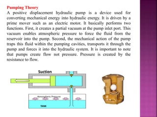
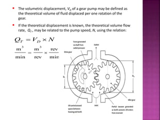
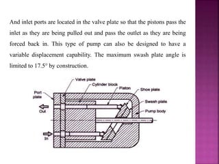
HYDRAULIC PUMPS
Learning Objectives
Upon completion of this chapter, the student should be able to:
 Classify the hydraulic pumps used in the industry.
 Differentiate between positive displacement and non-positive
displacement pumps.
 Explain the working and construction of gear, vane and piston
pumps.
 Evaluate the discharge parameters of gear, vane and piston pumps.
 Define mechanical, volumetric and overall efficiency of pumps.
 Evaluate the performance parameters of gear, vane and piston
pumps.
 Differentiate between internal and external gear pumps.
 Differentiate between a bent-axis piston pump and a swash plate.
 State the advantage of balance vane pumps.
 Explain cavitation and various means to control it.
 Explain the importance of noise control in pumps.
 Write a computer program to evaluate the performance of the
system.
Introduction
The function of a pump is to convert mechanical energy into hydraulic
energy. It is the heart of any hydraulic system because it generates the
force necessary to move the load. Mechanical energy is delivered to the
pump using a prime mover such as an electric motor. Partial vacuum is
created at the inlet due to the mechanical rotation of pump shaft. Vacuum
permits atmospheric pressure to force the fluid through the inlet line and
into the pump. The pump then pushes the fluid mechanically into the
fluid power actuated devices such as a motor or a cylinder.
Pumps are classified into three different ways and must be considered
in any discussion of fluid power equipment.
1. Classification based on displacement:
Non-positive displacement pumps (hydrodynamic pumps).
Positive displacement pumps (hydrostatic pumps).
2. Classification based on delivery:
 Constant delivery pumps.
 Variable delivery pumps.
3. Classification based on motion:
 Rotary pump.
 Reciprocating pump.
Non-Positive Displacement Pumps
Non-positive displacement pumps are primarily velocity-type units
that have a great deal of clearance between rotating and stationary
parts. Non-displacement pumps are characterized by a high slip that
increases as the back pressure increases, so that the outlet may be
completely closed without damage to the pump or system. Non-
positive pumps do not develop a high pressure but move a large
volume of fluid at low pressures. They have essentially no suction lift.
Because of large clearance space, these pumps are not self-priming. In
other words, the pumping action has too much clearance space to seal
against atmospheric pressure. The displacement between the inlet and
the outlet is not positive.
Therefore, the volume of fluid delivered by a pump depends on the
speed at which the pump is operated and the resistance at the
discharge side. As the resistance builds up at the discharge side, the
fluid slips back into the clearance spaces, or in other words, follows
the path of least resistance. When the resistance gets to a certain
value, no fluid gets delivered to the system and the volumetric
efficiency of the pump drops to zero for a given speed. These pumps
are not used in fluid power industry as they are not capable of
withstanding high pressure.
Their maximum capacity is limited to 17–20 bar. These types of
pumps are primarily used for transporting fluids such as water,
petroleum, etc., from one location to another considerable apart
location.
The two most common types of hydrodynamic pumps are the
centrifugal and the axial flow propeller pumps.
Advantages and disadvantages of non-positive displacement pumps
The advantages are as follows:
1.Non-displacement pumps have fewer moving parts.
2.Initial and maintenance cost is low.
3. They give smooth continuous flow.
4. They are suitable for handling almost all types of fluids including
slurries and sledges.
5.Their operation is simple and reliable.
The disadvantages are as follows:
1.Non-displacement pumps are not self-priming and hence they must be
positioned below the fluid level.
2. Discharge is a function of output resistance.
3.Low volumetric efficiency.
Positive Displacement Pumps
Positive displacement pumps, in contrast, have very little slips, are self-
priming and pump against very high pressures, but their volumetric
capacity is low. Positive displacement pumps have a very close
clearance between rotating and stationary parts and hence are self-
priming. Positive displacement pumps eject a fixed amount of fluid into
the hydraulic system per revolution of the pump shaft. Such pumps are
capable of overcoming the pressure resulting from mechanical loads on
the system as well as the resistance of flow due to friction. This
equipment must always be protected by relief valves to prevent damage
to the pump or system. By far, a majority of fluid power pumps fall in
this category, including gear, vane and piston pumps.
The advantages of positive displacement pumps over non-positive
displacement pumps are as follows:
1. They can operate at very high pressures of up to 800 bar (used for
lifting oils from very deep oil wells).
2. They can achieve a high volumetric efficiency of up to 98%.
3. They are highly efficient and almost constant throughout the
designed pressure range.
4. They are a compact unit, having a high power-to-weight ratio.
5. They can obtain a smooth and precisely controlled motion.
6. By proper application and control, they produce only the amount of
flow required to move the load at the desired velocity.
7. They have a great flexibility of performance. They can be made to
operate over a wide range of pressures and speeds.
Classification Based on Delivery
1.Constant Delivery Pumps
Constant volume pumps always deliver the same quantity of
fluid in a given time at the operating speed and temperature. These
pumps are generally used with relatively simple machines, such as
saws or drill presses or where a group of machines is operated with no
specific relationship among their relative speeds. Power for
reciprocating actuators is most often provided by constant volume
pumps.
2.Variable Delivery Pumps
The output of variable volume pumps may be varied either
manually or automatically with no change in the input speed to the
pump. Variable volume pumps are frequently used for rewinds,
constant tension devices or where a group of separate drives has an
integrated speed relationship such as a conveyor system or continuous
processing equipment.
Classification Based on Motion
This classification concerns the motion that may be either
rotary or reciprocating. It was of greater importance
when reciprocating pumps consisted only of a single or a
few relatively large cylinders and the discharge had a
large undesirable pulsation. Present-day reciprocating
pumps differ very little from rotary pumps in either
external appearance or the flow characteristics.
Differences between positive displacement pumps and
non-positive displacement pumps are enumerated in
Table 1.1.
Differences between positive displacement pumps and non-positive
displacement pumps
Positive Displacement Pumps Non-positive Displacement Pumps
The flow rate does not change
with head
The flow rate decreases with head
The flow rate is not much
affected by the viscosity of
fluid
The flow rate decreases with the
viscosity
Efficiency is almost constant
with head
Efficiency increases with head at
first and then decreases
Pumping Theory
A positive displacement hydraulic pump is a device used for
converting mechanical energy into hydraulic energy. It is driven by a
prime mover such as an electric motor. It basically performs two
functions. First, it creates a partial vacuum at the pump inlet port. This
vacuum enables atmospheric pressure to force the fluid from the
reservoir into the pump. Second, the mechanical action of the pump
traps this fluid within the pumping cavities, transports it through the
pump and forces it into the hydraulic system. It is important to note
that pumps create flow not pressure. Pressure is created by the
resistance to flow.
Suction
Atmospheric Pressure
TANK
Atmospheric pressure
TANK
High Pressure Outlet
Suction
TANK
High Pressure Outlet
Compression
Atmospheric Pressure
All pumps operate by creating a partial vacuum at the intake, and a
mechanical force at the outlet that induces flow. This action can be best
described by reference to a simple piston pump shown in Figures.
1. As the piston moves to the left, a partial vacuum is created in the
pump chamber that holds the outlet valve in place against its seat and
induces flow from the reservoir that is at a higher (atmospheric)
pressure. As this flow is produced, the inlet valve is temporarily
displaced by the force of fluid, permitting the flow into the pump
chamber (suction stroke).
2. When the piston moves to the right, the resistance at the valves
causes an immediate increase in the pressure that forces the inlet valve
against its seat and opens the outlet valve thereby permitting the fluid to
flow into the system. If the outlet port opens directly to the atmosphere,
the only pressure developed is the one required to open the outlet
valve(delivery stroke).
Gear Pumps
Gear pumps are less expensive but limited to pressures below 140 bar.
It is noisy in operation than either vane or piston pumps. Gear pumps
are invariably of fixed displacement type, which means that the
amount of fluid displaced for each revolution of the drive shaft is
theoretically constant.
External Gear Pumps
External gear pumps are the most popular hydraulic pumps in low-
pressure ranges due to their long operating life, high efficiency and low
cost. They are generally used in a simple machine. The most common
form of external gear pump is shown in Figure. It consist of a pump
housing in which a pair of precisely machined meshing gears runs with
minimal radial and axial clearance. One of the gears, called a driver, is
driven by a prime mover.
External Gear Pumps
The driver drives another gear called a follower. As the teeth of the
two gears separate, the fluid from the pump inlet gets trapped
between the rotating gear cavities and pump housing. The trapped
fluid is then carried around the periphery of the pump casing and
delivered to outlet port. The teeth of precisely meshed gears provide
almost a perfect seal between the pump inlet and the pump outlet.
When the outlet flow is resisted, pressure in the pump outlet chamber
builds up rapidly and forces the gear diagonally outward against the
pump inlet. When the system pressure increases, imbalance occurs.
This imbalance increases mechanical friction and the bearing load of
the two gears. Hence, the gear pumps are operated to the maximum
pressure rating stated by the manufacturer.
It is important to note that the inlet is at the point of separation and the
outlet at the point of mesh. These units are not reversible if the internal
bleeds for the bearings are to be drilled to both the inlet and outlet sides.
So that the manufacturer’s literature should be checked before
attempting a reversed installation. If they are not drilled in this manner,
the bearing may be permanently damaged as a result of inadequate
lubrications.
Advantages of gear pumps
The advantages are as follows:
1.They are self-priming.
2.They give constant delivery for a given speed.
3. They are compact and light in weight.
4. Volumetric efficiency is high.
disadvantages of gear pumps
1. The liquid to be pumped must be clean, otherwise it will damage
pump.
2. Variable speed drives are required to change the delivery.
3. If they run dry, parts can be damaged because the fluid to be
pumped is used as lubricant.
Expression for the theoretical flow rate of an external gear pump
Let
Do =the outside diameter of gear teeth
Di= the inside diameter of gear teeth
L =the width of gear teeth
N=the speed of pump in RPM
VD=the displacement of pump in m/rev
M= module of gear
z=number of gear teeth
= pressure angle
Volume displacement is
L
i
D
o
D
D
V 



  22
4

min
rev
rev
m
min
m
33

 NVQ DT
 The volumetric displacement, VD of a gear pump may be defined as
the theoretical volume of fluid displaced per one rotation of the
gear.
 If the theoretical displacement is known, the theoretical volume flow
rate, QT , may be related to the pump speed, N, using the relation:
PUMP PERFORMANCE
Flow (Q)
Speed (N)
Linear
relationship
Fig .1 Flow Vs Speed curve
Gear Pump: Volumetric Efficiency
 Because of the small clearance (about 20 µm) between the
teeth tip and pump housing, some of the oil at the at the
discharge port can leak directly back toward the suction port.
This means that the actual flow rate is QA is less than the
theoretical flow rate QT.
 The internal leakage, also called pump slippage is quantified by
the term volumetric efficiency, ηv .
T
A
v
Q
Q

Theoretical Flow
Curve
Actual Flow
Curve
Internal Loss
Fig. 2 Flow versus pressure at constant pressure
Pressure (P)
Flow (Q)
QT.QA
 The volumetric efficiency for positive displacement pumps
operating at design pressure is usually about 90%. It drops rapidly
if the pump is operated above its design pressure because pressure
increases the clearances though which leakage takes place.
 Pump manufacturers usually specify the volumetric efficiency at
the pump rated pressure, which is the design pressure at which the
pump may operate without causing mechanical damage to the
pump, and does not produce excessive leakage.
 Operating the pump above its rated pressure produces excessive leakage
and can damage the pump by distorting the casing and overloading the
shaft bearing.
 Pump operation above its rated pressure could occur when a high
resistance to flow is encountered. This could result from a large actuator
load or a closed (blocked) valve in the pump outlet line.
 Positive displacement pumps are usually protected from high pressure by
diverting pump flow to the oil tank through a pressure relief valve.
Example Gear Pump: Mizuhata Miniature Gear Pump
 Dimensions: 25 x 25 x 10 mm
 Used as a lubrication pump to drive oil for lubricating machine tools.
 Flow rate of 3 ml/min with pump speed of 1750 to 3450 rpm
 Can accommodate fluids of varying viscosity (32-1300mm2/s)
 Low to medium pressure head (2500-4000 psi) ~ (15,000 – 25,000 kPa).
Internal Gear Pumps
Another form of gear pump
is the internal gear pump,
which is illustrated in Fig.
They consist of two gears:
An external gear and an
internal gear. The crescent
placed in between these acts
as a seal between the suction
and discharge. When a
pump operates, the external
gear drives the internal gear
and both gears rotate in the
same direction.
The fluid fills the cavities formed by the rotating teeth and the
stationary crescent. Both the gears transport the fluid through the
pump. The crescent seals the low-pressure pump inlet from the high-
pressure pump outlet. The fluid volume is directly proportional to the
degree of separation and these units may be reversed without
difficulty. The major use for this type of pump occurs when a through
shaft is necessary, as in an automatic transmission. These pumps have
a higher pressure capability than external gear pumps.
Operation of an internal gear pump
Gerotor Pumps
Gerotor pumps operate in the
same manner as internal gear
pumps. The inner gear rotor is
called a Gerotor element. The
gerotor element is driven by a
prime mover and during the
operation drives outer gear
rotor around as they mesh
together. The gerotor has one
tooth less than the outer
internal idler gear.
Each tooth of the gerotor is always in sliding contact with the surface of the
outer element. The teeth of the two elements engage at just one place to seal
the pumping chambers from each other. On the right-hand side of the pump,
shown in Fig., pockets of increasing size are formed, while on the opposite
side, pockets decrease in size. The pockets of increasing size are suction
pockets and those of decreasing size are discharge pockets. Therefore, the
intake side of the pump is on the right and discharge side on the left.
Pumping chambers are formed by the adjacent pair of teeth, which are
constantly in contact with the outer element, except for clearance.
Refer to Figure, as the rotor is turned, its gear tips are accurately
machined sot hat they precisely follow the inner surface of the outer
element. The expanding chambers are created as the gear teeth
withdraw. The chamber
reaches its maximum size when the female tooth of the outer rotor
reaches the top dead center. During the second half of the revolution,
the spaces collapse, displacing the fluid to the outlet port formed at the
side plate. The geometric volume of the gerotor pump is given as
where b is the tooth height, Z is the number of rotor teeth, Amax is the
maximum area between male and female gears (unmeshed – occurs at
inlet) and Amin is the minimum area between male and female gears
(meshed – occurs at outlet).
Screw Pump
 In a screw pump, three
precision ground screws
meshing within a close fitting
housing deliver non pulsating
flow quietly and efficiently.
 The screw pump is an axial
flow positive displacement
unit. The two symmetrically
opposed idler rotors act as
rotating seals, confining the
fluid in a succession of
closures or stages.
 The idler rotors are in a rolling contact with the central power
rotor, and are free to float in their respective housing bores in a
hydrodynamic oil film.
 There are no radial bending loads on the rotor set, and axial
hydraulic forces are balanced, which eliminates the need for a
thrust bearing
Lobe Pump
 This pump operates in a fashion
similar to the external gear pump.
But unlike the external gear pump,
both lobes are driven externally and
they do not actually contact one
another. They are therefore quieter
in operation than other types of gear
pumps.
 Due to the smaller number of
mating elements, lobe pumps have a
higher volumetric displacement than
other types of gear pumps of the
same size and speed. They will,
however, produce a higher amount
of pulsation.
Unbalanced Vane Pump :
 The rotor contains radial slots and is splined to the drive shaft.
The rotor rotates inside a cam ring. Each slot contains a vane
designed to mate with the surface of the cam ring as the rotor
turns.
 Centrifugal forces keep the vanes in contact with the cam ring.
During rotation, the volume increases between the rotor and the
cam ring near the inlet and decreases near the outlet. This
causes a continuous suction and ejection of the fluid from the
inlet port to the discharge port.
Vane Pump: Volumetric Displacement
 The maximum volumetric displacement of the pump is the volume
between the rotor and the cam ring when the eccentricity is
maximum
  
 
  LeDDDV
LeDDDV
LDDDDDV
LRDCDDV
V
L
D
D
RC
RC
RCRC
D
R
C
max
max
2max
2
4max
4max
22
4max
)








 








(mntdisplacemevolumetric
(m)rotorofwidth
(m)rotorofdiamter
ring(m)camofdiamter
3
If the eccentricity is less than the maximum, the theoretical
volumetric displacement is
 eLDDDV
e
RC 
2
:

(m)tyeccentrici
 Some vane pumps have provision for mechanically varying the
eccentricity. Those pumps are called variable displacement pumps.
A hand wheel, or a pressure compensator can be used to move the
cam ring to change the eccentricity. The direction of flow through
the pump can be reversed by movement of the cam ring on either
side of center.
Pressure Compensated Vane Pump
 In a pressure compensated vane pump, system pressure acts directly
on the cam ring via a hydraulic piston on the right side as shown.
This forces the cam ring against the compensator spring-loaded piston
on the left side of the cam ring.
 If the discharge pressure is large enough, it overcomes the
compensator spring force, and shifts the cam ring to the left,
reducing the eccentricity. If the discharge pressure continues to
increase, zero eccentricity is finally achieved, and the pump flow
becomes zero. Such a pump has its built-in protection against
pressure buildup.
Flow –Rate Pressure Curve of a Pressure Compensated Vane Pump
Pdeadhea
d
Q
Slope determined by
stiffness of compensator
spring
e = emaxe = 0
Pcutoff
P
P-Q Curve of a pressure
compensated vane pump
 The pressure at which the
hydraulic force piston force is
equal to the compensator
spring force is called the
cutoff pressure, Pcutoff. The
eccentricity is below its
maximum value at a pressure
above Pcutoff.
 The pressure at which the
eccentricity is zero is called
the dead head pressure,
Pdeadhead. At dead head
pressure, no pumping occurs,
no power is wasted, and fluid
heating is reduced.
Balanced Vane Pump
 A side load is exerted on the bearing of a vane pump because of
pressure unbalance. This undesirable side load is also present in
gear pumps. These pumps are hydraulically unbalanced.
Balanced Vane Pump :
 A balanced vane pump is one which has two intakes and two outlets
diametrically opposite each other.
 This produces complete hydraulic balance and minimum side load is
exerted on the bearings. This permits the pump to operate at a higher
pressure.
 Instead of the circular cam ring, a balanced design vane pump has an
elliptic housing, which forms two separate pumping chambers on
opposite sides of the rotor.
 One disadvantage of a balanced vane pumps is that it can not be
designed as a variable displacement unit.
Advantages and disadvantages of Vane Pumps
The advantages of vane pumps are as follows:
1. Vane pumps are self-priming, robust and supply constant delivery at a
given speed.
2. They provide uniform discharge with negligible pulsations.
3. Their vanes are self-compensating for wear and vanes can be replaced
easily.
4. These pumps do not require check valves.
5. They are light in weight and compact.
6. They can handle liquids containing vapors and gases.
7. Volumetric and overall efficiencies are high.
8. Discharge is less sensitive to changes in viscosity and pressure
variations.
The disadvantages of vane pumps are as follows:
1. Relief valves are required to protect the pump in case of sudden
closure of delivery.
2. They are not suitable for abrasive liquids.
3. They require good seals.
4. They require good filtration systems and foreign particle can severely
damage pump.
Advantages and disadvantages of balanced vane pumps
The advantages of balanced vane pumps are as follows:
1. The balanced pump eliminates the bearing side loads and therefore
high operating pressure
can be used.
2.The service life is high compared to unbalanced type due to less wear
and tear.
The disadvantages of balanced vane pumps are as follows:
1. They are fixed displacement pumps.
2. Design is more complicated.
3. Manufacturing cost is high compared to unbalanced type.
Piston Pumps
Piston pumps are of the following two types:
1. Axial piston pump: These pumps are of two designs:
Bent-axis-type piston pump.
Swash-plate-type piston pump.
2. Radial piston pump.
1. Bent-Axis-Type Piston Pump
Schematic diagram and detailed cut section of bent axis type piston
pump is shown in Fig. It contains a cylinder block rotating with a drive
shaft. However, the centerline of the cylinder block is set at an offset
angle relative to the centerline of the drive shaft. The cylinder block
contains a number of pistons arranged along a circle. The piston rods are
connected to the drive shaft flange by a ball and socket joints. The
pistons are forced in and out of their bores as the distance between the
drive shaft flange and cylinder block changes. A universal link connects
the cylinder block to the drive shaft to provide alignment and positive
drive.
The volumetric displacement of the pump depends on the offset angle
. No flow is produced when the cylinder block is centerline.  can
vary from 0°to a maximum of about 30°.For a fixed displacement, units
are usually provided with 23° or 30° offset angles.
 The volumetric
displacement of the pump
varies with the offset
angle, α.
 No flow is produced
when the cylinder block
centerline is parallel to
the drive shaft centerline,
(α = 0)
 The offset angle can vary
between 0⁰ to a maximum
of about 30⁰. Fixed
displacement units are
usually provided with 23⁰
or 30⁰ offset angle.
Axial Piston Pump (Bent Axis Pump)
Volumetric Displacement and Theoretical Flow Rate
/min)(mrateflowvolume
)(mntdisplacemevolumetric
)(mareapiston
pistonsofnumber
mdiameter,circlepiston
mstroke,piston
angle,offset
3
3
2







T
D
Q
V
A
Y
D
S

α α
 
 
 
 



tan
tan
tan
tan
DANYNVQ
YADYASV
DS
DS
DT
D




Swash-Plate-Type Piston Pump
Schematic diagram of swash plate type piston pump is shown in Fig.
In this type, the cylinder block and drive shaft are located on the same
centerline. The pistons are connected to a shoe plate that bears against
an angled swash plate. As the cylinder rotates, the pistons reciprocate
because the piston shoes follow the angled surface of the swash plate.
The outlet
And inlet ports are located in the valve plate so that the pistons pass the
inlet as they are being pulled out and pass the outlet as they are being
forced back in. This type of pump can also be designed to have a
variable displacement capability. The maximum swash plate angle is
limited to 17.5° by construction.
Radial Piston Types
 The working pistons extend in a radial
direction symmetrically around the drive
shaft, in contrast to the axial piston pump.
 The stroke of each piston is caused by a
rotating block which houses the pistons.
The pistons are held against a fixed ring
which is placed eccentrically to the rotating
block. The pistons are held against the ring
by centrifugal force or by a set of springs.
 The inlet and outlet ports are placed in the
center cavity in the rotating block. The
placement is dependent on the direction of
eccentricity between the rotor and the ring.
In the figure shown, the inlet port is placed
in the upper part where suction takes place,
and the outlet port in the lower part, where
compression takes place.
Stationary Cylinder Radial Piston Pump :
Rotating Cylinder Radial Piston Pump :
Volumetric Displacement and Theoretical Flow Rate
/min)(mrateflowvolume
(mntdisplacemevolumetric
(mareapiston
pistonsofnumber
mdiameter,circlepiston
mstroke,piston
mty,eccentrici
3
3
2







T
D
Q
V
A
Y
D
S
E
)
)
DANENVQ
YAEYASV
ES
DT
D



Selection Criteria for Hydraulic Pump :
Comparison between Gear, Vane and Piston Pump:
Construction
•Gear : consist of two gears in mesh with each other, mounted inside a
closed casing. One is driver and the other is driven.
•Vane : consist of cylindrical rotor with radial slots. Vanes are inserted
in the slots. The rotor is mounted with an offset in the casing.
•Piston : consist of a cylindrical block with axial or radial bores.
Pistons are inserted in the bores. One end of the piston is connected to
rotating component.
Working :
•Gear : driver is rotated by means of prime mover that rotates driven.
The oil is sucked, trapped and carried from inlet to outlet.
•Vane : rotor causes the size of the pockets to grow and reduce
alternately. This causes filling of oil on suction side and delivery on the
other side.
•Piston : rotation of the moving component causes the pistons to
reciprocate in the bores. Half rotation of the cylinder block causes
suction of oil into the bores and the next half causes discharge.
Pump Calculations :
Pump Calculations :
The displacement of a pump operating at 1000 rpm at a
pressure of 70 bar is 100 cm3. the input torque is 120 N-m.
if the pump delivers 0.0015 m3/s of oil,
find : (1) Overall efficiency, (2) Theoretical torque.
Pumps

Pumps

  • 1.
    HYDRAULIC PUMPS Learning Objectives Uponcompletion of this chapter, the student should be able to:  Classify the hydraulic pumps used in the industry.  Differentiate between positive displacement and non-positive displacement pumps.  Explain the working and construction of gear, vane and piston pumps.  Evaluate the discharge parameters of gear, vane and piston pumps.  Define mechanical, volumetric and overall efficiency of pumps.  Evaluate the performance parameters of gear, vane and piston pumps.  Differentiate between internal and external gear pumps.  Differentiate between a bent-axis piston pump and a swash plate.  State the advantage of balance vane pumps.  Explain cavitation and various means to control it.  Explain the importance of noise control in pumps.  Write a computer program to evaluate the performance of the system.
  • 2.
    Introduction The function ofa pump is to convert mechanical energy into hydraulic energy. It is the heart of any hydraulic system because it generates the force necessary to move the load. Mechanical energy is delivered to the pump using a prime mover such as an electric motor. Partial vacuum is created at the inlet due to the mechanical rotation of pump shaft. Vacuum permits atmospheric pressure to force the fluid through the inlet line and into the pump. The pump then pushes the fluid mechanically into the fluid power actuated devices such as a motor or a cylinder.
  • 3.
    Pumps are classifiedinto three different ways and must be considered in any discussion of fluid power equipment. 1. Classification based on displacement: Non-positive displacement pumps (hydrodynamic pumps). Positive displacement pumps (hydrostatic pumps). 2. Classification based on delivery:  Constant delivery pumps.  Variable delivery pumps. 3. Classification based on motion:  Rotary pump.  Reciprocating pump.
  • 4.
    Non-Positive Displacement Pumps Non-positivedisplacement pumps are primarily velocity-type units that have a great deal of clearance between rotating and stationary parts. Non-displacement pumps are characterized by a high slip that increases as the back pressure increases, so that the outlet may be completely closed without damage to the pump or system. Non- positive pumps do not develop a high pressure but move a large volume of fluid at low pressures. They have essentially no suction lift. Because of large clearance space, these pumps are not self-priming. In other words, the pumping action has too much clearance space to seal against atmospheric pressure. The displacement between the inlet and the outlet is not positive.
  • 5.
    Therefore, the volumeof fluid delivered by a pump depends on the speed at which the pump is operated and the resistance at the discharge side. As the resistance builds up at the discharge side, the fluid slips back into the clearance spaces, or in other words, follows the path of least resistance. When the resistance gets to a certain value, no fluid gets delivered to the system and the volumetric efficiency of the pump drops to zero for a given speed. These pumps are not used in fluid power industry as they are not capable of withstanding high pressure. Their maximum capacity is limited to 17–20 bar. These types of pumps are primarily used for transporting fluids such as water, petroleum, etc., from one location to another considerable apart location. The two most common types of hydrodynamic pumps are the centrifugal and the axial flow propeller pumps.
  • 6.
    Advantages and disadvantagesof non-positive displacement pumps The advantages are as follows: 1.Non-displacement pumps have fewer moving parts. 2.Initial and maintenance cost is low. 3. They give smooth continuous flow. 4. They are suitable for handling almost all types of fluids including slurries and sledges. 5.Their operation is simple and reliable. The disadvantages are as follows: 1.Non-displacement pumps are not self-priming and hence they must be positioned below the fluid level. 2. Discharge is a function of output resistance. 3.Low volumetric efficiency.
  • 7.
    Positive Displacement Pumps Positivedisplacement pumps, in contrast, have very little slips, are self- priming and pump against very high pressures, but their volumetric capacity is low. Positive displacement pumps have a very close clearance between rotating and stationary parts and hence are self- priming. Positive displacement pumps eject a fixed amount of fluid into the hydraulic system per revolution of the pump shaft. Such pumps are capable of overcoming the pressure resulting from mechanical loads on the system as well as the resistance of flow due to friction. This equipment must always be protected by relief valves to prevent damage to the pump or system. By far, a majority of fluid power pumps fall in this category, including gear, vane and piston pumps.
  • 8.
    The advantages ofpositive displacement pumps over non-positive displacement pumps are as follows: 1. They can operate at very high pressures of up to 800 bar (used for lifting oils from very deep oil wells). 2. They can achieve a high volumetric efficiency of up to 98%. 3. They are highly efficient and almost constant throughout the designed pressure range. 4. They are a compact unit, having a high power-to-weight ratio. 5. They can obtain a smooth and precisely controlled motion. 6. By proper application and control, they produce only the amount of flow required to move the load at the desired velocity. 7. They have a great flexibility of performance. They can be made to operate over a wide range of pressures and speeds.
  • 9.
    Classification Based onDelivery 1.Constant Delivery Pumps Constant volume pumps always deliver the same quantity of fluid in a given time at the operating speed and temperature. These pumps are generally used with relatively simple machines, such as saws or drill presses or where a group of machines is operated with no specific relationship among their relative speeds. Power for reciprocating actuators is most often provided by constant volume pumps. 2.Variable Delivery Pumps The output of variable volume pumps may be varied either manually or automatically with no change in the input speed to the pump. Variable volume pumps are frequently used for rewinds, constant tension devices or where a group of separate drives has an integrated speed relationship such as a conveyor system or continuous processing equipment.
  • 10.
    Classification Based onMotion This classification concerns the motion that may be either rotary or reciprocating. It was of greater importance when reciprocating pumps consisted only of a single or a few relatively large cylinders and the discharge had a large undesirable pulsation. Present-day reciprocating pumps differ very little from rotary pumps in either external appearance or the flow characteristics. Differences between positive displacement pumps and non-positive displacement pumps are enumerated in Table 1.1.
  • 11.
    Differences between positivedisplacement pumps and non-positive displacement pumps Positive Displacement Pumps Non-positive Displacement Pumps The flow rate does not change with head The flow rate decreases with head The flow rate is not much affected by the viscosity of fluid The flow rate decreases with the viscosity Efficiency is almost constant with head Efficiency increases with head at first and then decreases
  • 12.
    Pumping Theory A positivedisplacement hydraulic pump is a device used for converting mechanical energy into hydraulic energy. It is driven by a prime mover such as an electric motor. It basically performs two functions. First, it creates a partial vacuum at the pump inlet port. This vacuum enables atmospheric pressure to force the fluid from the reservoir into the pump. Second, the mechanical action of the pump traps this fluid within the pumping cavities, transports it through the pump and forces it into the hydraulic system. It is important to note that pumps create flow not pressure. Pressure is created by the resistance to flow. Suction Atmospheric Pressure TANK
  • 13.
    Atmospheric pressure TANK High PressureOutlet Suction TANK High Pressure Outlet Compression Atmospheric Pressure
  • 14.
    All pumps operateby creating a partial vacuum at the intake, and a mechanical force at the outlet that induces flow. This action can be best described by reference to a simple piston pump shown in Figures. 1. As the piston moves to the left, a partial vacuum is created in the pump chamber that holds the outlet valve in place against its seat and induces flow from the reservoir that is at a higher (atmospheric) pressure. As this flow is produced, the inlet valve is temporarily displaced by the force of fluid, permitting the flow into the pump chamber (suction stroke). 2. When the piston moves to the right, the resistance at the valves causes an immediate increase in the pressure that forces the inlet valve against its seat and opens the outlet valve thereby permitting the fluid to flow into the system. If the outlet port opens directly to the atmosphere, the only pressure developed is the one required to open the outlet valve(delivery stroke).
  • 15.
    Gear Pumps Gear pumpsare less expensive but limited to pressures below 140 bar. It is noisy in operation than either vane or piston pumps. Gear pumps are invariably of fixed displacement type, which means that the amount of fluid displaced for each revolution of the drive shaft is theoretically constant. External Gear Pumps External gear pumps are the most popular hydraulic pumps in low- pressure ranges due to their long operating life, high efficiency and low cost. They are generally used in a simple machine. The most common form of external gear pump is shown in Figure. It consist of a pump housing in which a pair of precisely machined meshing gears runs with minimal radial and axial clearance. One of the gears, called a driver, is driven by a prime mover.
  • 16.
  • 17.
    The driver drivesanother gear called a follower. As the teeth of the two gears separate, the fluid from the pump inlet gets trapped between the rotating gear cavities and pump housing. The trapped fluid is then carried around the periphery of the pump casing and delivered to outlet port. The teeth of precisely meshed gears provide almost a perfect seal between the pump inlet and the pump outlet. When the outlet flow is resisted, pressure in the pump outlet chamber builds up rapidly and forces the gear diagonally outward against the pump inlet. When the system pressure increases, imbalance occurs. This imbalance increases mechanical friction and the bearing load of the two gears. Hence, the gear pumps are operated to the maximum pressure rating stated by the manufacturer.
  • 18.
    It is importantto note that the inlet is at the point of separation and the outlet at the point of mesh. These units are not reversible if the internal bleeds for the bearings are to be drilled to both the inlet and outlet sides. So that the manufacturer’s literature should be checked before attempting a reversed installation. If they are not drilled in this manner, the bearing may be permanently damaged as a result of inadequate lubrications. Advantages of gear pumps The advantages are as follows: 1.They are self-priming. 2.They give constant delivery for a given speed. 3. They are compact and light in weight. 4. Volumetric efficiency is high.
  • 19.
    disadvantages of gearpumps 1. The liquid to be pumped must be clean, otherwise it will damage pump. 2. Variable speed drives are required to change the delivery. 3. If they run dry, parts can be damaged because the fluid to be pumped is used as lubricant.
  • 20.
    Expression for thetheoretical flow rate of an external gear pump Let Do =the outside diameter of gear teeth Di= the inside diameter of gear teeth L =the width of gear teeth N=the speed of pump in RPM VD=the displacement of pump in m/rev M= module of gear z=number of gear teeth = pressure angle Volume displacement is L i D o D D V       22 4 
  • 21.
    min rev rev m min m 33   NVQ DT The volumetric displacement, VD of a gear pump may be defined as the theoretical volume of fluid displaced per one rotation of the gear.  If the theoretical displacement is known, the theoretical volume flow rate, QT , may be related to the pump speed, N, using the relation:
  • 22.
    PUMP PERFORMANCE Flow (Q) Speed(N) Linear relationship Fig .1 Flow Vs Speed curve
  • 23.
    Gear Pump: VolumetricEfficiency  Because of the small clearance (about 20 µm) between the teeth tip and pump housing, some of the oil at the at the discharge port can leak directly back toward the suction port. This means that the actual flow rate is QA is less than the theoretical flow rate QT.  The internal leakage, also called pump slippage is quantified by the term volumetric efficiency, ηv . T A v Q Q  Theoretical Flow Curve Actual Flow Curve Internal Loss Fig. 2 Flow versus pressure at constant pressure Pressure (P) Flow (Q) QT.QA
  • 24.
     The volumetricefficiency for positive displacement pumps operating at design pressure is usually about 90%. It drops rapidly if the pump is operated above its design pressure because pressure increases the clearances though which leakage takes place.  Pump manufacturers usually specify the volumetric efficiency at the pump rated pressure, which is the design pressure at which the pump may operate without causing mechanical damage to the pump, and does not produce excessive leakage.
  • 25.
     Operating thepump above its rated pressure produces excessive leakage and can damage the pump by distorting the casing and overloading the shaft bearing.  Pump operation above its rated pressure could occur when a high resistance to flow is encountered. This could result from a large actuator load or a closed (blocked) valve in the pump outlet line.  Positive displacement pumps are usually protected from high pressure by diverting pump flow to the oil tank through a pressure relief valve.
  • 26.
    Example Gear Pump:Mizuhata Miniature Gear Pump  Dimensions: 25 x 25 x 10 mm  Used as a lubrication pump to drive oil for lubricating machine tools.  Flow rate of 3 ml/min with pump speed of 1750 to 3450 rpm  Can accommodate fluids of varying viscosity (32-1300mm2/s)  Low to medium pressure head (2500-4000 psi) ~ (15,000 – 25,000 kPa).
  • 27.
    Internal Gear Pumps Anotherform of gear pump is the internal gear pump, which is illustrated in Fig. They consist of two gears: An external gear and an internal gear. The crescent placed in between these acts as a seal between the suction and discharge. When a pump operates, the external gear drives the internal gear and both gears rotate in the same direction.
  • 28.
    The fluid fillsthe cavities formed by the rotating teeth and the stationary crescent. Both the gears transport the fluid through the pump. The crescent seals the low-pressure pump inlet from the high- pressure pump outlet. The fluid volume is directly proportional to the degree of separation and these units may be reversed without difficulty. The major use for this type of pump occurs when a through shaft is necessary, as in an automatic transmission. These pumps have a higher pressure capability than external gear pumps.
  • 29.
    Operation of aninternal gear pump
  • 30.
    Gerotor Pumps Gerotor pumpsoperate in the same manner as internal gear pumps. The inner gear rotor is called a Gerotor element. The gerotor element is driven by a prime mover and during the operation drives outer gear rotor around as they mesh together. The gerotor has one tooth less than the outer internal idler gear.
  • 31.
    Each tooth ofthe gerotor is always in sliding contact with the surface of the outer element. The teeth of the two elements engage at just one place to seal the pumping chambers from each other. On the right-hand side of the pump, shown in Fig., pockets of increasing size are formed, while on the opposite side, pockets decrease in size. The pockets of increasing size are suction pockets and those of decreasing size are discharge pockets. Therefore, the intake side of the pump is on the right and discharge side on the left.
  • 32.
    Pumping chambers areformed by the adjacent pair of teeth, which are constantly in contact with the outer element, except for clearance. Refer to Figure, as the rotor is turned, its gear tips are accurately machined sot hat they precisely follow the inner surface of the outer element. The expanding chambers are created as the gear teeth withdraw. The chamber reaches its maximum size when the female tooth of the outer rotor reaches the top dead center. During the second half of the revolution, the spaces collapse, displacing the fluid to the outlet port formed at the side plate. The geometric volume of the gerotor pump is given as where b is the tooth height, Z is the number of rotor teeth, Amax is the maximum area between male and female gears (unmeshed – occurs at inlet) and Amin is the minimum area between male and female gears (meshed – occurs at outlet).
  • 33.
    Screw Pump  Ina screw pump, three precision ground screws meshing within a close fitting housing deliver non pulsating flow quietly and efficiently.  The screw pump is an axial flow positive displacement unit. The two symmetrically opposed idler rotors act as rotating seals, confining the fluid in a succession of closures or stages.
  • 34.
     The idlerrotors are in a rolling contact with the central power rotor, and are free to float in their respective housing bores in a hydrodynamic oil film.  There are no radial bending loads on the rotor set, and axial hydraulic forces are balanced, which eliminates the need for a thrust bearing
  • 36.
    Lobe Pump  Thispump operates in a fashion similar to the external gear pump. But unlike the external gear pump, both lobes are driven externally and they do not actually contact one another. They are therefore quieter in operation than other types of gear pumps.  Due to the smaller number of mating elements, lobe pumps have a higher volumetric displacement than other types of gear pumps of the same size and speed. They will, however, produce a higher amount of pulsation.
  • 38.
  • 39.
  • 40.
     The rotorcontains radial slots and is splined to the drive shaft. The rotor rotates inside a cam ring. Each slot contains a vane designed to mate with the surface of the cam ring as the rotor turns.  Centrifugal forces keep the vanes in contact with the cam ring. During rotation, the volume increases between the rotor and the cam ring near the inlet and decreases near the outlet. This causes a continuous suction and ejection of the fluid from the inlet port to the discharge port.
  • 41.
    Vane Pump: VolumetricDisplacement  The maximum volumetric displacement of the pump is the volume between the rotor and the cam ring when the eccentricity is maximum        LeDDDV LeDDDV LDDDDDV LRDCDDV V L D D RC RC RCRC D R C max max 2max 2 4max 4max 22 4max )                   (mntdisplacemevolumetric (m)rotorofwidth (m)rotorofdiamter ring(m)camofdiamter 3
  • 42.
    If the eccentricityis less than the maximum, the theoretical volumetric displacement is  eLDDDV e RC  2 :  (m)tyeccentrici  Some vane pumps have provision for mechanically varying the eccentricity. Those pumps are called variable displacement pumps. A hand wheel, or a pressure compensator can be used to move the cam ring to change the eccentricity. The direction of flow through the pump can be reversed by movement of the cam ring on either side of center.
  • 43.
    Pressure Compensated VanePump  In a pressure compensated vane pump, system pressure acts directly on the cam ring via a hydraulic piston on the right side as shown. This forces the cam ring against the compensator spring-loaded piston on the left side of the cam ring.
  • 44.
     If thedischarge pressure is large enough, it overcomes the compensator spring force, and shifts the cam ring to the left, reducing the eccentricity. If the discharge pressure continues to increase, zero eccentricity is finally achieved, and the pump flow becomes zero. Such a pump has its built-in protection against pressure buildup.
  • 45.
    Flow –Rate PressureCurve of a Pressure Compensated Vane Pump Pdeadhea d Q Slope determined by stiffness of compensator spring e = emaxe = 0 Pcutoff P P-Q Curve of a pressure compensated vane pump  The pressure at which the hydraulic force piston force is equal to the compensator spring force is called the cutoff pressure, Pcutoff. The eccentricity is below its maximum value at a pressure above Pcutoff.  The pressure at which the eccentricity is zero is called the dead head pressure, Pdeadhead. At dead head pressure, no pumping occurs, no power is wasted, and fluid heating is reduced.
  • 46.
    Balanced Vane Pump A side load is exerted on the bearing of a vane pump because of pressure unbalance. This undesirable side load is also present in gear pumps. These pumps are hydraulically unbalanced.
  • 48.
  • 49.
     A balancedvane pump is one which has two intakes and two outlets diametrically opposite each other.  This produces complete hydraulic balance and minimum side load is exerted on the bearings. This permits the pump to operate at a higher pressure.  Instead of the circular cam ring, a balanced design vane pump has an elliptic housing, which forms two separate pumping chambers on opposite sides of the rotor.  One disadvantage of a balanced vane pumps is that it can not be designed as a variable displacement unit.
  • 50.
    Advantages and disadvantagesof Vane Pumps The advantages of vane pumps are as follows: 1. Vane pumps are self-priming, robust and supply constant delivery at a given speed. 2. They provide uniform discharge with negligible pulsations. 3. Their vanes are self-compensating for wear and vanes can be replaced easily. 4. These pumps do not require check valves. 5. They are light in weight and compact. 6. They can handle liquids containing vapors and gases. 7. Volumetric and overall efficiencies are high. 8. Discharge is less sensitive to changes in viscosity and pressure variations.
  • 51.
    The disadvantages ofvane pumps are as follows: 1. Relief valves are required to protect the pump in case of sudden closure of delivery. 2. They are not suitable for abrasive liquids. 3. They require good seals. 4. They require good filtration systems and foreign particle can severely damage pump.
  • 52.
    Advantages and disadvantagesof balanced vane pumps The advantages of balanced vane pumps are as follows: 1. The balanced pump eliminates the bearing side loads and therefore high operating pressure can be used. 2.The service life is high compared to unbalanced type due to less wear and tear. The disadvantages of balanced vane pumps are as follows: 1. They are fixed displacement pumps. 2. Design is more complicated. 3. Manufacturing cost is high compared to unbalanced type.
  • 53.
    Piston Pumps Piston pumpsare of the following two types: 1. Axial piston pump: These pumps are of two designs: Bent-axis-type piston pump. Swash-plate-type piston pump. 2. Radial piston pump.
  • 54.
    1. Bent-Axis-Type PistonPump Schematic diagram and detailed cut section of bent axis type piston pump is shown in Fig. It contains a cylinder block rotating with a drive shaft. However, the centerline of the cylinder block is set at an offset angle relative to the centerline of the drive shaft. The cylinder block contains a number of pistons arranged along a circle. The piston rods are connected to the drive shaft flange by a ball and socket joints. The pistons are forced in and out of their bores as the distance between the drive shaft flange and cylinder block changes. A universal link connects the cylinder block to the drive shaft to provide alignment and positive drive.
  • 55.
    The volumetric displacementof the pump depends on the offset angle . No flow is produced when the cylinder block is centerline.  can vary from 0°to a maximum of about 30°.For a fixed displacement, units are usually provided with 23° or 30° offset angles.
  • 56.
     The volumetric displacementof the pump varies with the offset angle, α.  No flow is produced when the cylinder block centerline is parallel to the drive shaft centerline, (α = 0)  The offset angle can vary between 0⁰ to a maximum of about 30⁰. Fixed displacement units are usually provided with 23⁰ or 30⁰ offset angle. Axial Piston Pump (Bent Axis Pump)
  • 57.
    Volumetric Displacement andTheoretical Flow Rate /min)(mrateflowvolume )(mntdisplacemevolumetric )(mareapiston pistonsofnumber mdiameter,circlepiston mstroke,piston angle,offset 3 3 2        T D Q V A Y D S  α α            tan tan tan tan DANYNVQ YADYASV DS DS DT D    
  • 58.
    Swash-Plate-Type Piston Pump Schematicdiagram of swash plate type piston pump is shown in Fig. In this type, the cylinder block and drive shaft are located on the same centerline. The pistons are connected to a shoe plate that bears against an angled swash plate. As the cylinder rotates, the pistons reciprocate because the piston shoes follow the angled surface of the swash plate. The outlet
  • 59.
    And inlet portsare located in the valve plate so that the pistons pass the inlet as they are being pulled out and pass the outlet as they are being forced back in. This type of pump can also be designed to have a variable displacement capability. The maximum swash plate angle is limited to 17.5° by construction.
  • 63.
    Radial Piston Types The working pistons extend in a radial direction symmetrically around the drive shaft, in contrast to the axial piston pump.  The stroke of each piston is caused by a rotating block which houses the pistons. The pistons are held against a fixed ring which is placed eccentrically to the rotating block. The pistons are held against the ring by centrifugal force or by a set of springs.  The inlet and outlet ports are placed in the center cavity in the rotating block. The placement is dependent on the direction of eccentricity between the rotor and the ring. In the figure shown, the inlet port is placed in the upper part where suction takes place, and the outlet port in the lower part, where compression takes place.
  • 64.
  • 65.
  • 66.
    Volumetric Displacement andTheoretical Flow Rate /min)(mrateflowvolume (mntdisplacemevolumetric (mareapiston pistonsofnumber mdiameter,circlepiston mstroke,piston mty,eccentrici 3 3 2        T D Q V A Y D S E ) ) DANENVQ YAEYASV ES DT D   
  • 67.
    Selection Criteria forHydraulic Pump :
  • 68.
    Comparison between Gear,Vane and Piston Pump: Construction •Gear : consist of two gears in mesh with each other, mounted inside a closed casing. One is driver and the other is driven. •Vane : consist of cylindrical rotor with radial slots. Vanes are inserted in the slots. The rotor is mounted with an offset in the casing. •Piston : consist of a cylindrical block with axial or radial bores. Pistons are inserted in the bores. One end of the piston is connected to rotating component.
  • 69.
    Working : •Gear :driver is rotated by means of prime mover that rotates driven. The oil is sucked, trapped and carried from inlet to outlet. •Vane : rotor causes the size of the pockets to grow and reduce alternately. This causes filling of oil on suction side and delivery on the other side. •Piston : rotation of the moving component causes the pistons to reciprocate in the bores. Half rotation of the cylinder block causes suction of oil into the bores and the next half causes discharge.
  • 70.
  • 73.
    Pump Calculations : Thedisplacement of a pump operating at 1000 rpm at a pressure of 70 bar is 100 cm3. the input torque is 120 N-m. if the pump delivers 0.0015 m3/s of oil, find : (1) Overall efficiency, (2) Theoretical torque.