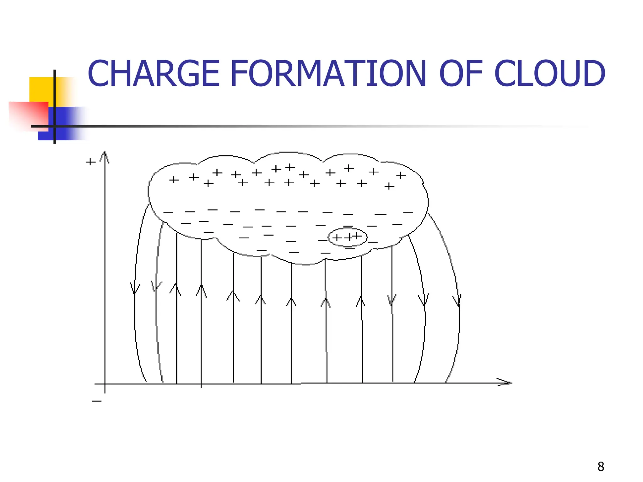
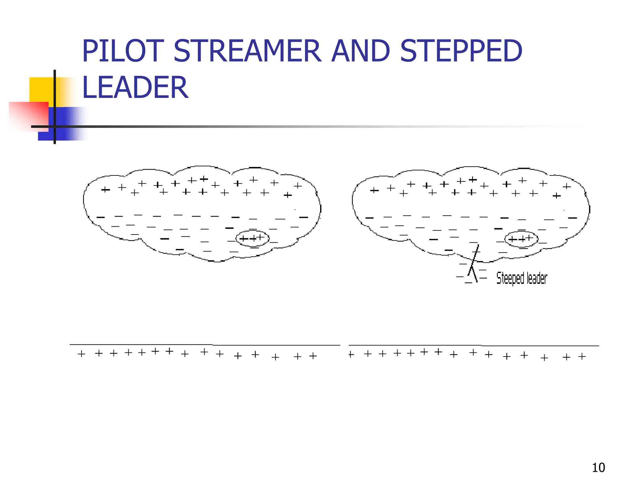
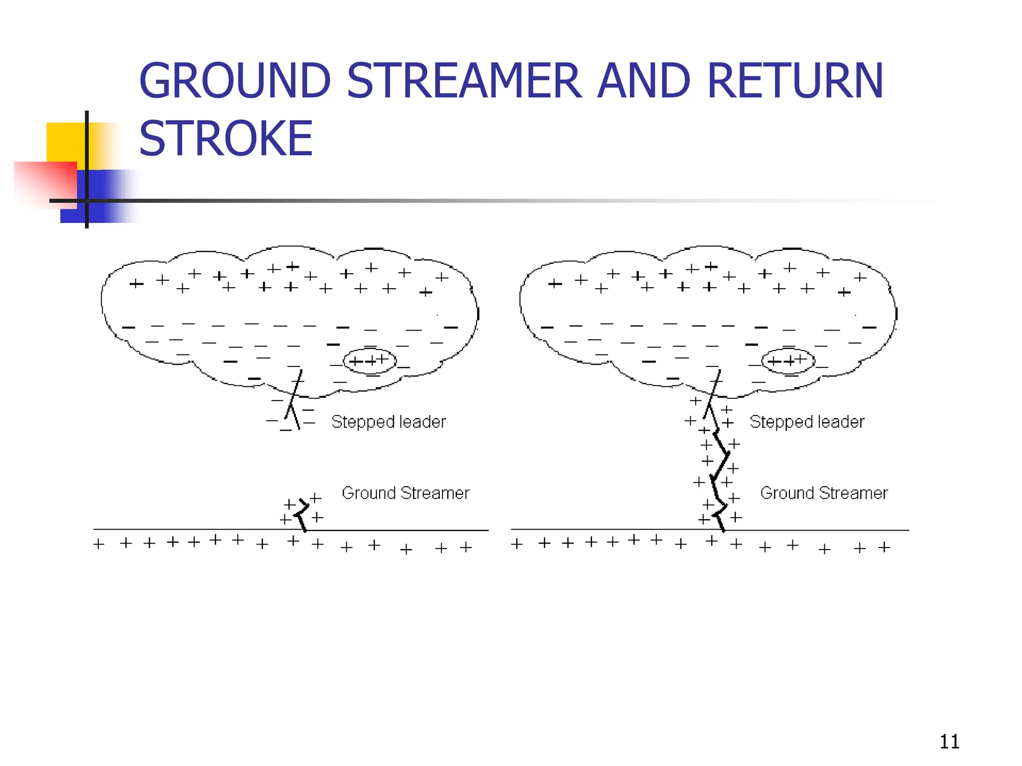
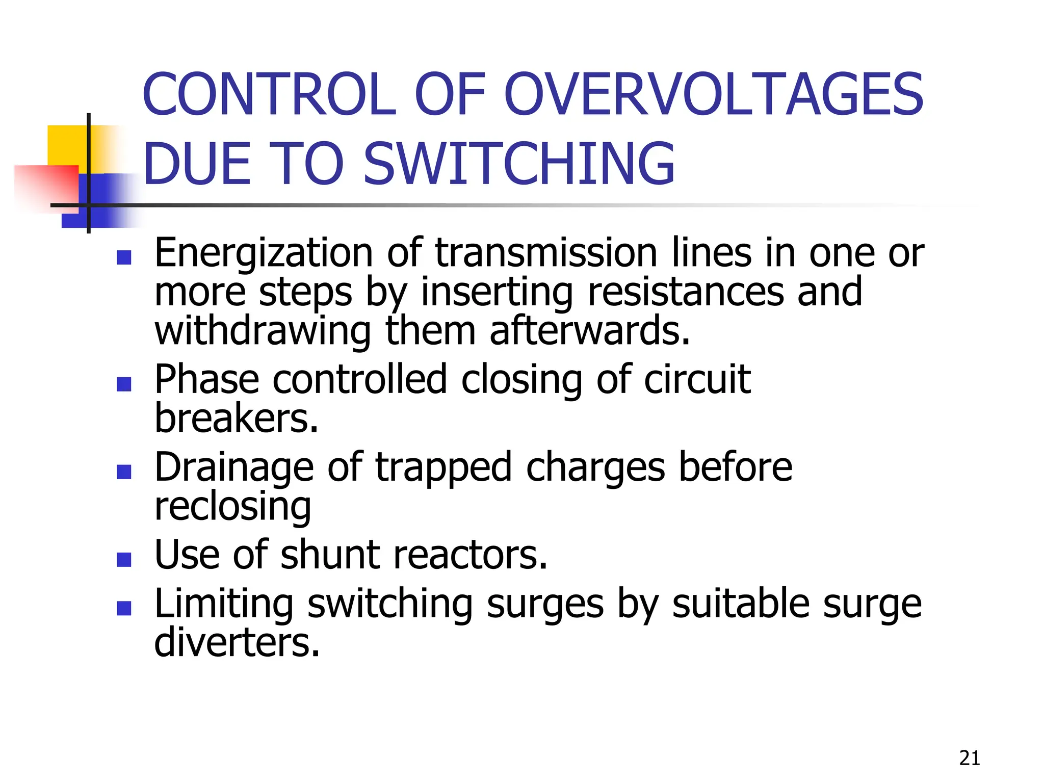
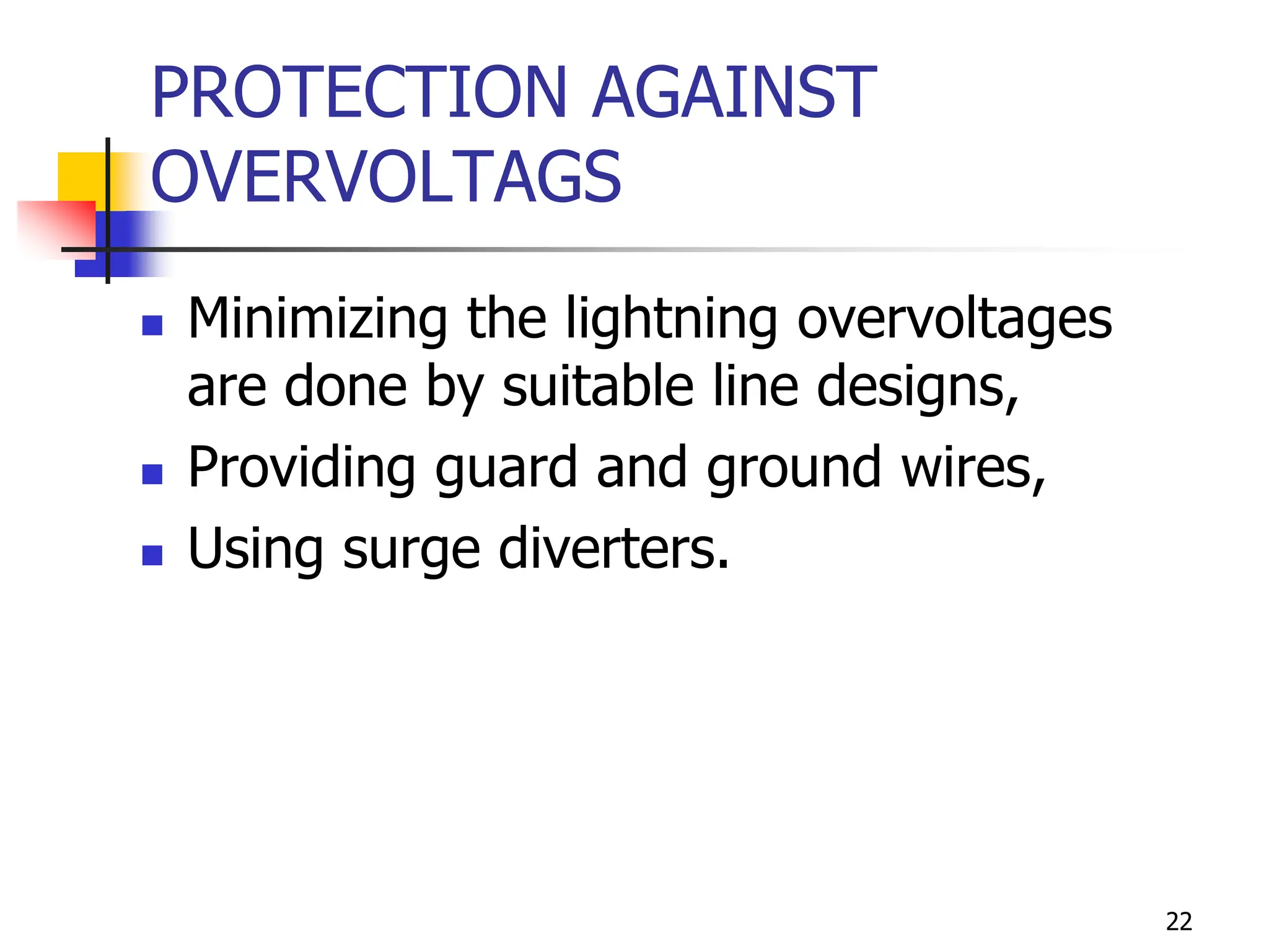
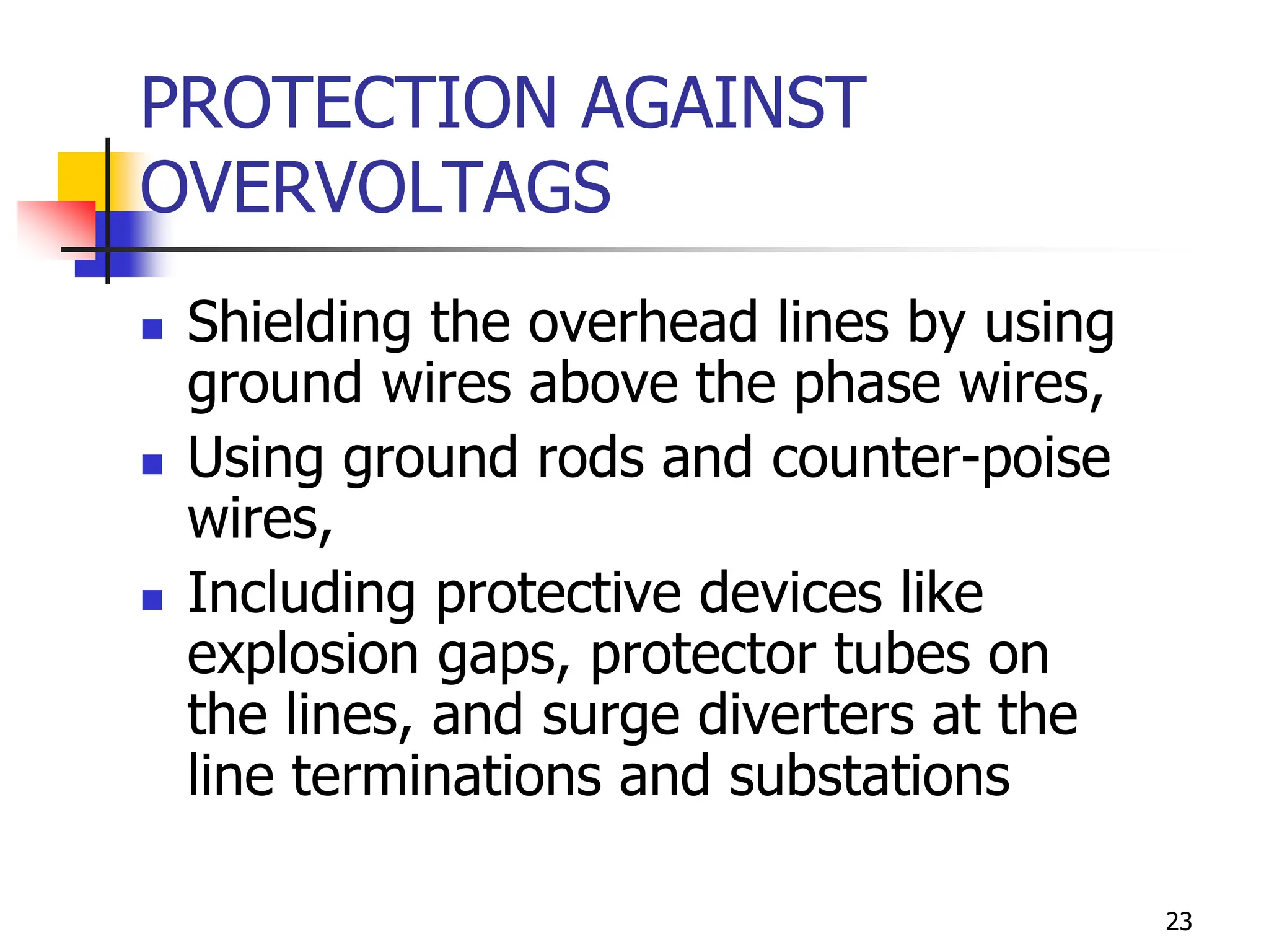
HIGH VOLTAGE ENGINEERING
Presented By
P.Sindhu
Asst.Prof
EEE Dept
OVER VOLTAGES IN ELECTRICAL
POWER SYSTEMS
3
LIGHTING
 Causes of over voltage
 Lightning phenomenon
 Charge formation of Lightning
 Rate of Charging of thunder cloud
 Mechanism of lightning strokes
 Characteristics of Lightning strokes
4
LIGHTING
 Factors contributing to good line
design
 Protection afforded by ground wires.
 Tower footing resistance
 Interaction between lightning and
power system
 Mathematical model of Lightning
5
Causes of Lightning
 Lightning phenomenon
- peak discharge in which charge
accumulated in the cloud into
neighbouring cloud or to the ground
 Electrode separation – cloud to cloud
or cloud to ground is about 10 km or
more
6
CHARGE FORMATION OF CLOUD
 Positive and negative charges
become separated by heavy air
current with ice crystals in the upper
part and rain in the lower region.
 Charge separation depends on
height of cloud (200 – 10,000m).
 Charge centers at a distance about
300 – 2km
7
CHARGE FORMATION OF CLOUD
 Charge inside the cloud – 1 to 100 C
 Cloud potential – 107 to 108 V
 Gradient within a cloud – 100 V/cm
 Gradient at initial discharge point –
10kV/cm
 Energy at discharge – 250 kWhr
8
CHARGE FORMATION OF CLOUD
9
MECHANISM OF LIGHTNING FLASH
 Pilot streamer and Stepped leader
 Ground streamer and return stroke
 Subsequent strokes
10
PILOT STREAMER AND STEPPED
LEADER
11
GROUND STREAMER AND RETURN
STROKE
12
CHARACTERISTICS OF LIGHTNING
STROKES
 Current-time characteristics
 Time to peak or Rate of rise
 Probability distribution of current and
time
 Wave shapes of lightning voltage and
current
13
LIGHTNING CURRENT
 Short front time - 10µs
 Tail time – several ms.
14
RATE OF RISE
 50% lightning stroke current –
greater than 7.5kA/µs.
 10% lightning strokes current –
exceeds 25 kA/µs.
 Stroke current above half value –
more than 30µs.
15
SURGE VOLTAGE
 Maximum surge voltage in
transmission line – 5MV
 Most of the surge voltage is less than
1000 kV on line.
 Front time – 2 to 10 µs
 Tail time – 20 to 100 µs
 Rate of rise of voltage – 1MV/ µs
16
LIGHTNING STROKES
 Direct stroke
directly discharges on to
transmission line or line wires
 Induced stroke
cloud generates negative charge at
its base, the earth object develop
induced positive charge
17
OVER VOLTAGE DUE TO SWITCHING
SURGES
INTRODUCTION
 In switching, the over voltage thus
generated last for longer durations and
therefore are severe and more dangerous
to the system
 The switching over voltages depends on
the normal voltage of the system and
hence increase with increased system
voltage
18
ORIGIN OF SWITCHING
SURGES
 Making and breaking of electric
circuits with switchgear may results
in abnormal over voltages in power
systems having large inductances
and capacitances.
 over voltages may go as high as 6
times the normal power frequency
voltage.
19
ORIGIN OF SWITCHING
SURGES
 In circuit breaking operation switching
surges with a high rate of rise of voltage
may cause repeated restriking of the arc
between the contacts of a circuit breaker,
thereby causing destruction of the circuit
breaker contacts.
 Switching surges may include high natural
frequencies of the system, a damped
normal frequency voltage component, or
restriking and recovery voltage of the
system with successive reflected waves
from terminations.
20
CHARACTERISTICS OF
SWITCHING SURGES
 De-energizing of transmission lines, cables,
shunt capacitor, banks, etc.
 Disconnection of unloaded transformers,
reactors, etc.
 Energization or reclosing of lines and
reactive loads.
 Sudden switching off of loads.
 Short circuit and fault clearances.
 Resonance phenomenon like ferro-
resonance, arcing grounds, etc.
21
CONTROL OF OVERVOLTAGES
DUE TO SWITCHING
 Energization of transmission lines in one or
more steps by inserting resistances and
withdrawing them afterwards.
 Phase controlled closing of circuit
breakers.
 Drainage of trapped charges before
reclosing
 Use of shunt reactors.
 Limiting switching surges by suitable surge
diverters.
22
PROTECTION AGAINST
OVERVOLTAGS
 Minimizing the lightning overvoltages
are done by suitable line designs,
 Providing guard and ground wires,
 Using surge diverters.
23
PROTECTION AGAINST
OVERVOLTAGS
 Shielding the overhead lines by using
ground wires above the phase wires,
 Using ground rods and counter-poise
wires,
 Including protective devices like
explosion gaps, protector tubes on
the lines, and surge diverters at the
line terminations and substations
Thank You
24

protection against overvoltages in power system

  • 1.
    HIGH VOLTAGE ENGINEERING PresentedBy P.Sindhu Asst.Prof EEE Dept
  • 2.
    OVER VOLTAGES INELECTRICAL POWER SYSTEMS
  • 3.
    3 LIGHTING  Causes ofover voltage  Lightning phenomenon  Charge formation of Lightning  Rate of Charging of thunder cloud  Mechanism of lightning strokes  Characteristics of Lightning strokes
  • 4.
    4 LIGHTING  Factors contributingto good line design  Protection afforded by ground wires.  Tower footing resistance  Interaction between lightning and power system  Mathematical model of Lightning
  • 5.
    5 Causes of Lightning Lightning phenomenon - peak discharge in which charge accumulated in the cloud into neighbouring cloud or to the ground  Electrode separation – cloud to cloud or cloud to ground is about 10 km or more
  • 6.
    6 CHARGE FORMATION OFCLOUD  Positive and negative charges become separated by heavy air current with ice crystals in the upper part and rain in the lower region.  Charge separation depends on height of cloud (200 – 10,000m).  Charge centers at a distance about 300 – 2km
  • 7.
    7 CHARGE FORMATION OFCLOUD  Charge inside the cloud – 1 to 100 C  Cloud potential – 107 to 108 V  Gradient within a cloud – 100 V/cm  Gradient at initial discharge point – 10kV/cm  Energy at discharge – 250 kWhr
  • 8.
  • 9.
    9 MECHANISM OF LIGHTNINGFLASH  Pilot streamer and Stepped leader  Ground streamer and return stroke  Subsequent strokes
  • 10.
    10 PILOT STREAMER ANDSTEPPED LEADER
  • 11.
  • 12.
    12 CHARACTERISTICS OF LIGHTNING STROKES Current-time characteristics  Time to peak or Rate of rise  Probability distribution of current and time  Wave shapes of lightning voltage and current
  • 13.
    13 LIGHTNING CURRENT  Shortfront time - 10µs  Tail time – several ms.
  • 14.
    14 RATE OF RISE 50% lightning stroke current – greater than 7.5kA/µs.  10% lightning strokes current – exceeds 25 kA/µs.  Stroke current above half value – more than 30µs.
  • 15.
    15 SURGE VOLTAGE  Maximumsurge voltage in transmission line – 5MV  Most of the surge voltage is less than 1000 kV on line.  Front time – 2 to 10 µs  Tail time – 20 to 100 µs  Rate of rise of voltage – 1MV/ µs
  • 16.
    16 LIGHTNING STROKES  Directstroke directly discharges on to transmission line or line wires  Induced stroke cloud generates negative charge at its base, the earth object develop induced positive charge
  • 17.
    17 OVER VOLTAGE DUETO SWITCHING SURGES INTRODUCTION  In switching, the over voltage thus generated last for longer durations and therefore are severe and more dangerous to the system  The switching over voltages depends on the normal voltage of the system and hence increase with increased system voltage
  • 18.
    18 ORIGIN OF SWITCHING SURGES Making and breaking of electric circuits with switchgear may results in abnormal over voltages in power systems having large inductances and capacitances.  over voltages may go as high as 6 times the normal power frequency voltage.
  • 19.
    19 ORIGIN OF SWITCHING SURGES In circuit breaking operation switching surges with a high rate of rise of voltage may cause repeated restriking of the arc between the contacts of a circuit breaker, thereby causing destruction of the circuit breaker contacts.  Switching surges may include high natural frequencies of the system, a damped normal frequency voltage component, or restriking and recovery voltage of the system with successive reflected waves from terminations.
  • 20.
    20 CHARACTERISTICS OF SWITCHING SURGES De-energizing of transmission lines, cables, shunt capacitor, banks, etc.  Disconnection of unloaded transformers, reactors, etc.  Energization or reclosing of lines and reactive loads.  Sudden switching off of loads.  Short circuit and fault clearances.  Resonance phenomenon like ferro- resonance, arcing grounds, etc.
  • 21.
    21 CONTROL OF OVERVOLTAGES DUETO SWITCHING  Energization of transmission lines in one or more steps by inserting resistances and withdrawing them afterwards.  Phase controlled closing of circuit breakers.  Drainage of trapped charges before reclosing  Use of shunt reactors.  Limiting switching surges by suitable surge diverters.
  • 22.
    22 PROTECTION AGAINST OVERVOLTAGS  Minimizingthe lightning overvoltages are done by suitable line designs,  Providing guard and ground wires,  Using surge diverters.
  • 23.
    23 PROTECTION AGAINST OVERVOLTAGS  Shieldingthe overhead lines by using ground wires above the phase wires,  Using ground rods and counter-poise wires,  Including protective devices like explosion gaps, protector tubes on the lines, and surge diverters at the line terminations and substations
  • 24.