Downloaded 719 times


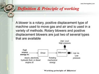
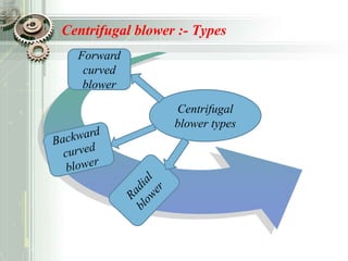
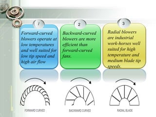
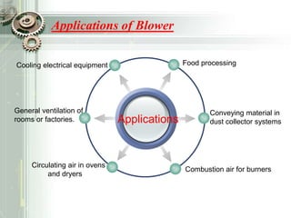
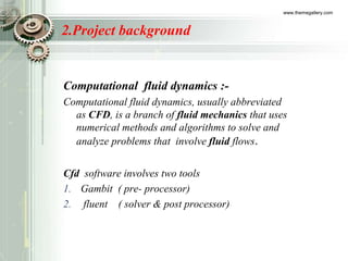

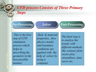

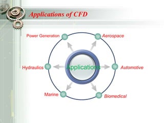
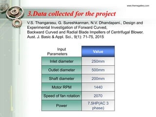
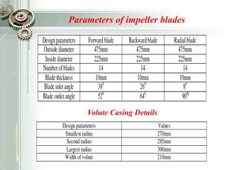
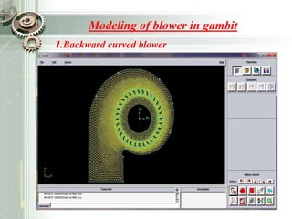
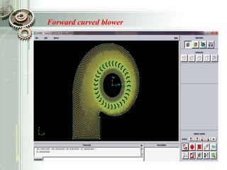
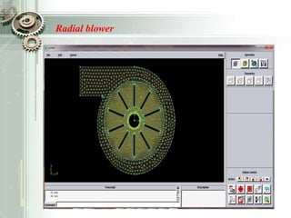
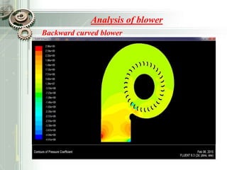
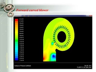
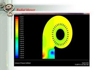


This document summarizes a student project analyzing the performance of a centrifugal blower using computational fluid dynamics (CFD). The project team used CFD software to model and analyze blowers with different impeller blade designs, including backward curved, forward curved, and radial blades. They collected input parameters for the blower and blade designs. The team reviewed previous literature on blower blade design and performance. They modeled the different blower designs in Gambit and analyzed the results in Fluent to compare blower performance.


![EDE_Report_Final_14-12-22[1] (AutoRecovered).docx](https://cdn.slidesharecdn.com/ss_thumbnails/edereportfinal14-12-221autorecovered-230403165017-b6177214-thumbnail.jpg?width=640&height=640&fit=bounds)