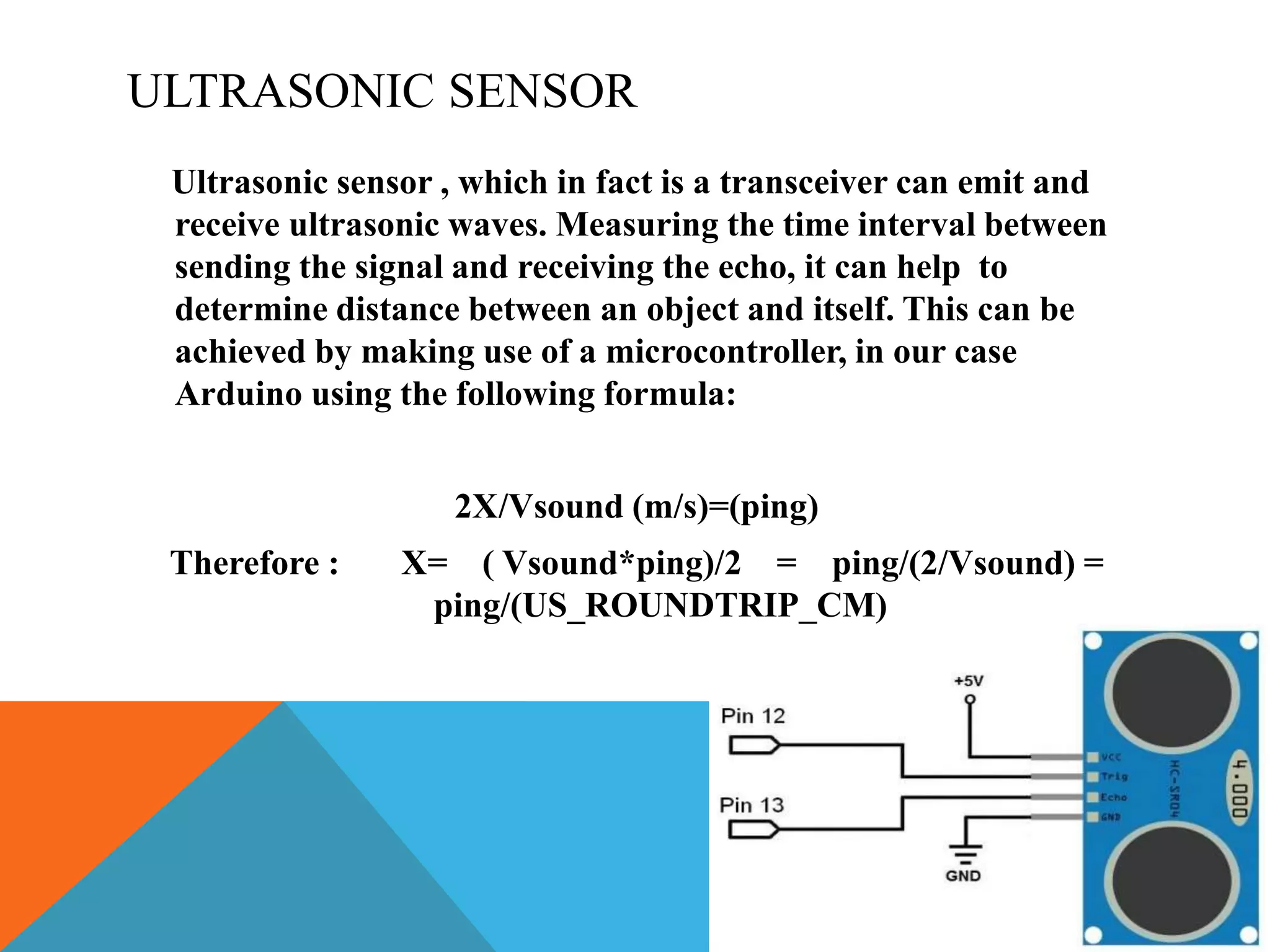
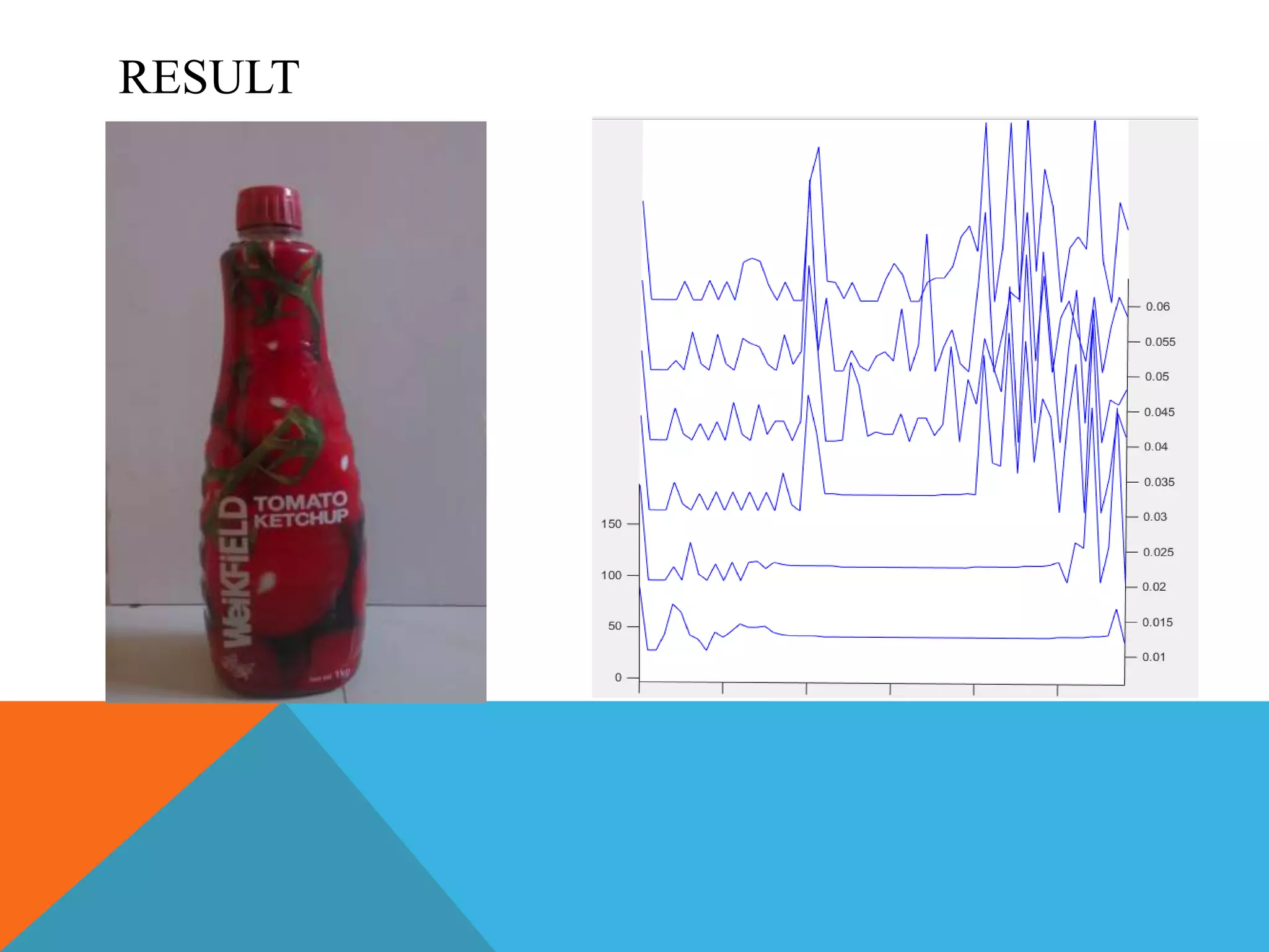
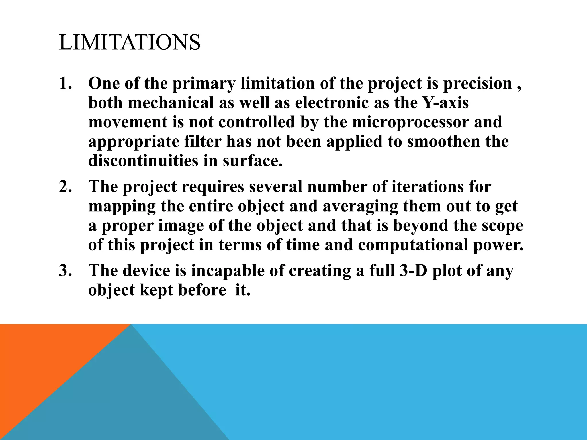
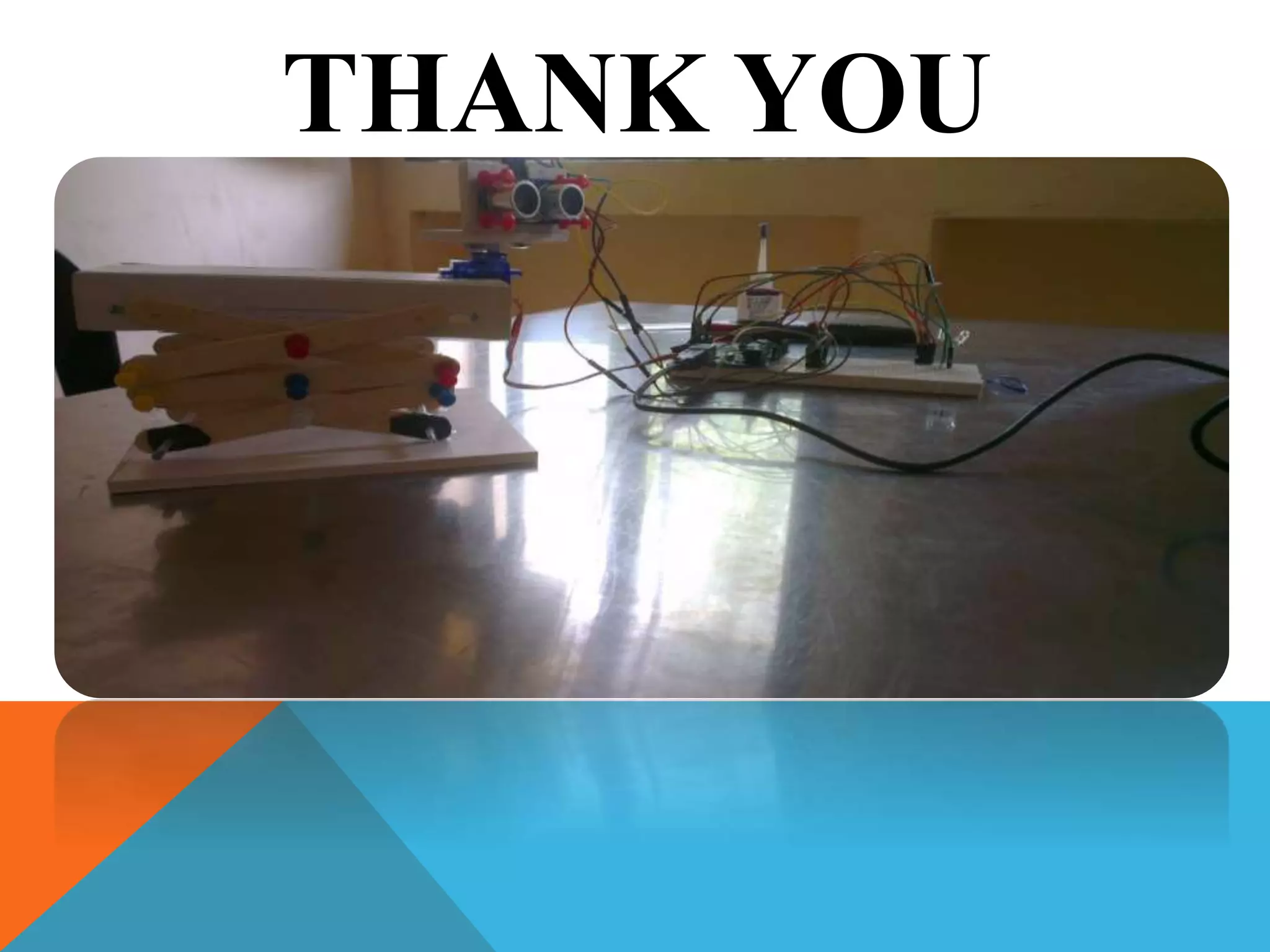
APRAMEYO ROY SC14B079
NIKUNJ GUPTA
SC14B105
OBJECTIVE
The main goal of this project is to try and get a rough map of an
object placed in front of our device. This has to be done via an
ultrasonic sensor which feeds in serial input to the
microcontroller which then interprets it to get the distance
between itself and the object. This information is then fed
serially to the computer (MATLAB) which processes it and plots
the required mesh by stacking inputs from several iterations of
the process.
COMPONENTS REQUIRED
Arduino, PC with MATLAB software, ultrasonic sensor, LEDs,
connecting wires, lifting mechanism, servo motor.
ULTRASONIC SENSOR
Ultrasonic sensor , which in fact is a transceiver can emit and
receive ultrasonic waves. Measuring the time interval between
sending the signal and receiving the echo, it can help to
determine distance between an object and itself. This can be
achieved by making use of a microcontroller, in our case
Arduino using the following formula:
2X/Vsound (m/s)=(ping)
Therefore : X= ( Vsound*ping)/2 = ping/(2/Vsound) =
ping/(US_ROUNDTRIP_CM)
WORKING
A servo is used to rotate the ultrasonic sensor in X-axis so that the
sensor can measure distance between itself and different points
on the object . Further the sensor is moved along the Y-axis
using a lifting mechanism.
Each position on the Y-axis corresponds to a single iteration of the
ultrasonic sensor’s 60o
sweep around the object using servo
motor . Several iterations are taken according to the position of
the sensor in the Y-axis and then finally stacked together to form
a rough sketch of the object.
The LED’s are used to indicate end of current process.
RESULT
LIMITATIONS
1. One of the primary limitation of the project is precision ,
both mechanical as well as electronic as the Y-axis
movement is not controlled by the microprocessor and
appropriate filter has not been applied to smoothen the
discontinuities in surface.
2. The project requires several number of iterations for
mapping the entire object and averaging them out to get
a proper image of the object and that is beyond the scope
of this project in terms of time and computational power.
3. The device is incapable of creating a full 3-D plot of any
object kept before it.
SCOPE
1. The project can be extended further for getting full 3-D plots
by moving the device around the object. Remotely controlling
the device including movement in all the axes can be made
possible.
2. Better filtration techniques can be used to get more real and
clearer picture of the object.
3. Finally it can be used to minimize threats by mapping a room
in a dark environment and get an image of what lies ahead.
THANK YOU

Project

  • 1.
  • 2.
    OBJECTIVE The main goalof this project is to try and get a rough map of an object placed in front of our device. This has to be done via an ultrasonic sensor which feeds in serial input to the microcontroller which then interprets it to get the distance between itself and the object. This information is then fed serially to the computer (MATLAB) which processes it and plots the required mesh by stacking inputs from several iterations of the process. COMPONENTS REQUIRED Arduino, PC with MATLAB software, ultrasonic sensor, LEDs, connecting wires, lifting mechanism, servo motor.
  • 3.
    ULTRASONIC SENSOR Ultrasonic sensor, which in fact is a transceiver can emit and receive ultrasonic waves. Measuring the time interval between sending the signal and receiving the echo, it can help to determine distance between an object and itself. This can be achieved by making use of a microcontroller, in our case Arduino using the following formula: 2X/Vsound (m/s)=(ping) Therefore : X= ( Vsound*ping)/2 = ping/(2/Vsound) = ping/(US_ROUNDTRIP_CM)
  • 4.
    WORKING A servo isused to rotate the ultrasonic sensor in X-axis so that the sensor can measure distance between itself and different points on the object . Further the sensor is moved along the Y-axis using a lifting mechanism. Each position on the Y-axis corresponds to a single iteration of the ultrasonic sensor’s 60o sweep around the object using servo motor . Several iterations are taken according to the position of the sensor in the Y-axis and then finally stacked together to form a rough sketch of the object. The LED’s are used to indicate end of current process.
  • 5.
  • 6.
    LIMITATIONS 1. One ofthe primary limitation of the project is precision , both mechanical as well as electronic as the Y-axis movement is not controlled by the microprocessor and appropriate filter has not been applied to smoothen the discontinuities in surface. 2. The project requires several number of iterations for mapping the entire object and averaging them out to get a proper image of the object and that is beyond the scope of this project in terms of time and computational power. 3. The device is incapable of creating a full 3-D plot of any object kept before it.
  • 7.
    SCOPE 1. The projectcan be extended further for getting full 3-D plots by moving the device around the object. Remotely controlling the device including movement in all the axes can be made possible. 2. Better filtration techniques can be used to get more real and clearer picture of the object. 3. Finally it can be used to minimize threats by mapping a room in a dark environment and get an image of what lies ahead.
  • 8.