1. P a g e | 1
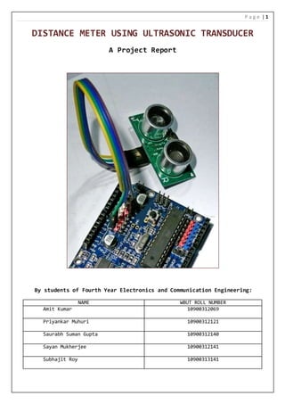
DISTANCE METER USING ULTRASONIC TRANSDUCER
A Project Report
By students of Fourth Year Electronics and Communication Engineering:
NAME WBUT ROLL NUMBER
Amit Kumar 10900312069
Priyankar Muhuri 10900312121
Saurabh Suman Gupta 10900312140
Sayan Mukherjee 10900312141
Subhajit Roy 10900313141
2. P a g e | 2
ABSTRACT
Distance measurement is one of the most common mensuration activities.
The development of a distance meter is implored in this project report. The
proposed meter will utilise the method of ultrasonic reflection to provide
distance measurements. This comparatively simple method is intended to
make the meter simpler in comparison to the more common laser range
finding type of instruments.
3. P a g e | 3
CONTENTS
1. Background
2. Literature review
3. Methodology: Part 1
4. Methodology: Part 2
5. Methodology: Part 3
6. Methodology: Part 4
7. Data Analysis
8. Discussion
9. Bibliography
10. Appendix
4. P a g e | 4
BACKGROUND
Distance measurement is one of the most essential requirements
of human activity all over the world, being used in diverse
fields like scientific research, engineering, infrastructure
development, and every imaginable daily activity. A distance
meter is used for the measurement of distance. A commercially
available example of a distance meter is shown below:
5. P a g e | 5
The methods generally used for distance measurement are
following:
Laser Rangefinding
A laser rangefinder is a rangefinder which uses a laser
beam to determine the distance to an object. The most
common form of laser rangefinder operates on the time of
flight principle by sending a laser pulse in a narrow beam
towards the object and measuring the time taken by the
pulse to be reflected off the target and returned to the
sender. Due to the high speed of light, this technique is
not appropriate for high precision sub-millimetre
measurements, where triangulation and other techniques are
often used.
Ultrasonic Reflection Rangefinding:
In this method short pulses of high frequency ultrasound
are emitted and a detector is used to detect the reflected
pulses. The distance measurement is carried out by
measuring the time interval between the transmission and
reception of the ultrasonic pulses. This method is simpler
compared to the above method, but is suitable for small
distances only.
In this project we will use the ultrasonic distance measurement
method as it is simpler in design and is economical compared to
laser range finding method.
6. P a g e | 6
LITERATURE REVIEW
1. Basic Principles
A Laser Distance Meter sends out a finely focussed pulse
of light to the target and detects the reflection. The
meter measures the time between those two events, and
converts this to a distance.
2. Why not use a Tape?
A Distance Meter is generally accurate to within a few
millimetres; certainly equalling a tape for larger
distances and the line is always dead straight with no
bending or sagging. There is a choice of units, and there
is no risk of misreading, as with the intermediate marks
on a tape.
3. Laser versus Ultrasonic
Disadvantages with ultrasonic distance meters are
elaborated in the diagram:
(A) Obstructions can be a problem
(B) Small target, small signal
A B
7. P a g e | 7
METHODOLOGY: PART 1
The block diagram of the project is as follows:
The ultrasonic module automatically sends eight 40 kHz pulses
and detect whether there is a pulse signal back.
If the signal returns, through high level, time of high
output IO duration is the time from sending ultrasonic pulse
to the return signal.
Test distance = (high level time × velocity of sound) / 2
The distance obtained is converted to the appropriate units
and is transmitted to the host personal computer via a
Universal Serial Bus (USB) link.
ARDUINO
CONTROLLER
BOARD
ULTRASONIC
TRANSDUCER
PERSONAL
COMPUTER
USB
OBSTACLE
8. P a g e | 8
METHODOLOGY: PART 2
1. HC-SR04 ultrasonic sensor
The HC-SR04 ultrasonic sensor uses sonar to determine
distance to an object. It offers excellent non-contact range
detection with high accuracy and stable readings in an easy-
to-use package, from 2 cm to 400 cm or 1” to 13 feet. Its
operation is not affected by sunlight or black material like
sharp rangefinders are (although acoustically soft materials
like cloth can be difficult to detect). It comes complete
with ultrasonic transmitter and receiver module.
Features:
● Power Supply: +5V DC
● Quiescent Current : <2mA
● Working Current: 15mA
● Effectual Angle: <15°
9. P a g e | 9
● Ranging Distance: 2cm – 400 cm/1" - 13ft
● Resolution: 0.3 cm
● Measuring Angle: 30 degree
● Trigger Input Pulse width: 10uS
● Dimension: 45mm x 20mm x 15mm
Pin Configuration:
VCC = +5VDC
Trig = Trigger input of Sensor
Echo = Echo output of Sensor
GND = GND
Product Specification and Limitations:
Parameter Min Typ. Max Unit
Operating Voltage 4.50 5.0 5.5 V
Quiescent Current 1.5 2 2.5 mA
Working Current 10 15 20 mA
Ultrasonic Frequency - 40 - kHz
Operation:
The timing diagram of HC-SR04 is shown. To start measurement,
Trig of SR04 must receive a pulse of high (5V) for at least
10us, this will initiate the sensor will transmit out 8 cycle
of ultrasonic burst at 40kHz and wait for the reflected
ultrasonic burst. When the sensor detected ultrasonic from
receiver, it will set the Echo pin to high (5V) and delay for
a period (width) which proportion to distance. To obtain the
distance, measure the width (Ton) of Echo pin.
10. P a g e | 10
● Time = Width of Echo pulse, in uS (micro second)
● Distance in centimetres = Time / 58
● Distance in inches = Time / 148
● Or we can utilize the speed of sound, which is 340m/s
11. P a g e | 11
METHODOLOGY: PART 3
2. Microcontroller Based Development Board
Arduino is open-source computer hardware and software
company, project and user community that designs and
manufactures microcontroller-based kits for building digital
devices and interactive objects that can sense and control
objects in the physical world.
The project is based on microcontroller board designs,
manufactured by several vendors, using various
microcontrollers. These systems provide sets of digital and
analog I/O pins that can be interfaced to various expansion
boards ("shields") and other circuits. The boards feature
serial communications interfaces, including USB on some
models, for loading programs from personal computers. For
12. P a g e | 12
programming the microcontrollers, the Arduino project
provides an integrated development environment (IDE) based on
the Processing project, which includes support for the C, C++
programming languages.
Hardware:
An Arduino board consists of an Atmel 8-, 16- or 32-bit AVR
microcontroller with complementary components that facilitate
programming and incorporation into other circuits.
Official Arduinos have used the megaAVR series of chips,
specifically the ATmega8, ATmega168, ATmega328, ATmega1280, and
ATmega2560. A handful of other processors have been used by Arduino
compatibles. Most boards include a 5 V linear regulator and a
16 MHz crystal oscillator or ceramic resonator in some variants.
An Arduino's microcontroller is also pre-programmed with a boot
loader that simplifies uploading of programs to the on-chip flash
memory, compared with other devices that typically need an external
programmer. This makes using an Arduino more straightforward by
allowing the use of an ordinary computer as the programmer.
When using the Arduino integrated development environment, all
boards are programmed over a serial connection. Its implementation
varies with the hardware version. Some serial Arduino boards
contain a level shifter circuit to convert between RS-232 logic
levels and TTL-level signals. Current Arduino boards are programmed
via Universal Serial Bus (USB).
13. P a g e | 13
METHODOLOGY: PART 4
3. Integrated Development Environment
AVR Microcontroller programs may be written in any programming
language with a compiler that produces binary machine code. Atmel
provides a development environment for their microcontrollers.
14. P a g e | 14
After compilation and linking with the GNU toolchain, also
including with the IDE distribution, the Arduino IDE employs the
program avrdude to convert the executable code into a text file in
hexadecimal coding that is loaded into the Arduino board by a
loader program in the board's firmware.
The Arduino project provides the Arduino integrated development
environment (IDE), which is a cross-platform application written in
Java. It originated from the IDE for the Processing programming
language project and the Wiring project. It is designed to
introduce programming to artists and other newcomers unfamiliar
with software development. It includes a code editor with features
such as syntax highlighting, brace matching, and automatic
indentation, and provides simple one-click mechanism for compiling
and loading programs to an Arduino board. A program written with
the IDE for Arduino is called a ‘sketch’.
15. P a g e | 15
DATA ANALYSIS
The flowchart of the microcontroller firmware is as follows:
START
INITIALISE TIME, DIST, SUM, AVG, I = 0
IS
PROMPT
PRESENT
?
WAIT
PREDEFINED
TIME
SET TRIGGER TO HIGH
WAIT 10 ms
SET TIME = HIGH PULSE
WIDTH ON ECHO PIN
A
I = 2?
TRUE
TRUE
FALSE
FALSE
INCREMENT I
SUM = SUM + DIST
DIST = TIME / 58
B
16. P a g e | 16
The flowchart displayed above is for the program which is intended
to be the final revision of the ‘Distance Meter’ project. The
program in C programming language is in initial stages of
development hence full functionality is not achieved yet.
The initial program is able to perform the structural function of
calculating a single value of distance by the proper initialisation
of the ultrasonic sensor.
To make the unit having a greater stand-alone utility the option of
alternate displays is thought out. To achieve greater program
reliability the use of the newPing software library is intended.
A
AVG = SUM/ 3
DISPLAY
AVG
B
17. P a g e | 17
DISCUSSION
The described project provides for a simple and effective method
of distance measurement. But it has a few limitations:
The effective range is limited between 2 cm to 300 cm.
Precise measurements are difficult when the obstacle surface
is not smooth.
Improvements can be made in the following areas:
Use of a higher power ultrasonic module.
Better computer software to present and process the acquired
distance measurement data.
18. P a g e | 18
BIBLIOGRAPHY
HC – SR04 ultrasonic module datasheet
www.cytron.com.my
Arduino
en.wikipedia.org/Arduino
Laser rangefinder - Wikipedia, the free encyclopedia
fluke.com/fluke-416d-laser-distance-meter-product
NewPing Library
http://playground.arduino.cc/Code/NewPing
19. P a g e | 19
APPENDIX
Content for literature review sourced from the following:
Cordex Technologies
Why use a Laser Distance Meter? Understanding the
technology
http://www.transcat.com/media/pdf/cordex-laser-distance-
meters.pdf
Design and Application of Distance Measure Ultrasonic Sensor
Shuhai Wang, Qiuzhen Liu, Shuwang Chen, Yuxi Xue
Affiliated with Institute of Information Science &
Engineering, Hebei University of Science and Technology
http://link.springer.com/chapter/10.1007%2F978-3-642-
31528-2_18#page-1