Magnetic field of a straight wire official.nb
•
1 like•287 views

Write up for the magnetic field of a long straight wire. This is a calculus based physics lab, but can be revised for algebra or conceptual physics.

Recommended
More Related Content
Similar to Magnetic field of a straight wire official.nb
Similar to Magnetic field of a straight wire official.nb (20)
Recently uploaded
Recently uploaded (20)
Magnetic field of a straight wire official.nb
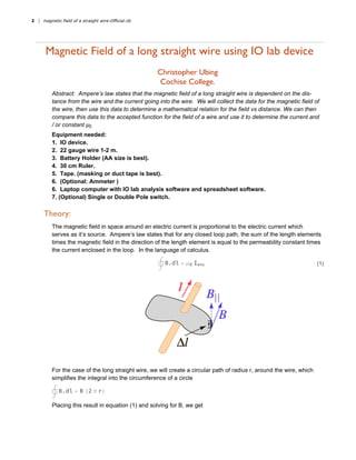
- 1. Magnetic Field of a long straight wire using IO lab device Christopher Ubing Cochise College. Abstract: Ampere’s law states that the magnetic field of a long straight wire is dependent on the dis- tance from the wire and the current going into the wire. We will collect the data for the magnetic field of the wire, then use this data to determine a mathematical relation for the field vs distance. We can then compare this data to the accepted function for the field of a wire and use it to determine the current and / or constant μ0 Equipment needed: 1. IO device. 2. 22 gauge wire 1-2 m. 3. Battery Holder (AA size is best). 4. 30 cm Ruler. 5. Tape. (masking or duct tape is best). 6. (Optional: Ammeter ) 6. Laptop computer with IO lab analysis software and spreadsheet software. 7. (Optional) Single or Double Pole switch. Theory: The magnetic field in space around an electric current is proportional to the electric current which serves as it’s source. Ampere’s law states that for any closed loop path, the sum of the length elements times the magnetic field in the direction of the length element is equal to the permeability constant times the current enclosed in the loop. In the language of calculus. B.dl = μ0 Ienc (1) For the case of the long straight wire, we will create a circular path of radius r, around the wire, which simplifies the integral into the circumference of a circle B.dl = B (2 π r) Placing this result in equation (1) and solving for B, we get 2 magnetic field of a straight wire-Official.nb
- 2. 2 π r B = μ0 Ienc B = μ0 Ienc 2 π r (2) In this experiment we want to examine the field strength vs distance away from a long copper wire. The challenge with this experiment, is that there is always a certain amount of magnetic field due to the field of the Earth. Since there is no way to shield our experiment from the Earth’s magnetic field, we will have to account for it in the data that we take. So, the first part of our procedure is to discover the magnetic field strength along the direction perpendicular to the wire without current. This quantity will be Be, and we will check to see if it changes as we move our sensor away from the wire. In the second part of the experiment, we will run current through the wire and take measurements of the magnetic field. After correcting for the Earth’s field, we will compare our data with what is accepted, and use it to determine the current running through the wire. Hardware Setup: The hardware for this experiment consists of the IO device, a fixed length of wire, a single or double throw switch, a battery holder and 2 AA batteries. The setup is shown in Figure 1. Note the location of the Magnetometer which should be placed as close to the level of the wire as it can. magnetic field of a straight wire-Official.nb 3
- 3. Fig 1: Experiment setup with all equipment needed to run the lab. Orient the remote so that the +z axis is facing towards the wire as shown. Logger Pro Setup: In this experiment, you will be taking data in a graphical format. You will need to extract this data from the graph, and place it in a separate table in Logger Pro or a spreadsheet program. You will need a total of 13 columns, 6 of which will be calculated. The set up is shown in the figure below. Note that the columns z (m) 1/z(m), Bxw, Byw, Bzw and mag B are all calculated columns. The first two transform the recorded distance into meters and 1/ meters respectively. The Biw columns are defined so as to subtract the magnetic field of the Earth from the measured magnetic field thus giving you the component of the field for the wire. The last column is the magnitude of the wire magnetic field. I have also included a column for the current being measured by the ammeter. You do not need to include this column if you are not using an ammeter in the circuit. Procedure 1. Determine Magnetic field of the Earth at your location. Since we are interested in the magnetic field due to the wire, it is necessary to determine the back- ground magnetic field of your location. So, with the lab set up, we take magnetic field readings with no current flowing in the wire. Note, we are only interested in the magnetic field along the z axis of the device. 1. Connect dongle to computer. 2. Turn on IO lab device and software. 3. Measure the length of the wire you have between the tape. L = ___ ___ ___ You will place the IO lab device at a distance of 1 cm from the center of the wire, as shown in figure 1. 4. In the sensor list on the right hand side of the screen, select the Magnetometer. 4 magnetic field of a straight wire-Official.nb
- 4. current flowing in the wire. Note, we are only interested in the magnetic field along the z axis of the device. 1. Connect dongle to computer. 2. Turn on IO lab device and software. 3. Measure the length of the wire you have between the tape. L = ___ ___ ___ You will place the IO lab device at a distance of 1 cm from the center of the wire, as shown in figure 1. 4. In the sensor list on the right hand side of the screen, select the Magnetometer. 5. Without connecting the batteries to the wire, click record, and let it run for 10 seconds. 6. Click on the Analysis button of the software and mouse over the graph. Record the μ values from your graph. These are the average values of the field. 7. Repeat this process for distances z=3, 5, 7, 9 and 11 cm from the wire. Remember to record the values of the field for each distance. This will be your baseline magnetic field that you will have to subtract out from your data. Procedure 2. Taking Data with the current on. In this part, you will obtain the magnetic field reading of the wire+Earth field. 1. Click the reset button on the software tool bar. This will clear your graph. 2. Place the AA batteries in the holder. Using clip leads, connect the red line of the battery holder to the switch. Connect the switch to the wire and using another clip lead connect the other end of the wire to the battery holder. This will form a circuit shown in Fig. 3. Fig 3: Circuit for long straight wire experiment. 3. Return remote to d=1 cm, Set data collection time to 10 sec. 4. Click record, and close the switch so that current flows. Once the recording stops, open the switch to shut down the current. 5. Mouse over the graph to get the average value of the components for the portion of the graph after you closed the switch. 6. Record these in your spreadsheet or Logger Pro document. Click AddRun button in the IO lab soft- ware, and repeat this process for d=3, 5, 7, 9 and 11 cm. Note that as you move further away from the wire, the changes in the graph for the magnetic field will become smaller, so you should keep track of the time that you closed the switch. Analysis of the data. In this section, we are going to use graphs to determine the mathematical meaning of the data we have collected. Note that all units should be SI. magnetic field of a straight wire-Official.nb 5
- 5. In this section, we are going to use graphs to determine the mathematical meaning of the data we have collected. Note that all units should be SI. 1. Create a plot in Logger Pro for the magnitude of the field vs the distance in meters. Using the curve fitting features of Logger Pro find a curve fit for your data. What are the meanings of the coefficients from your curve fit. 2. Create a plot in your Logger Pro document for the magnitude of the field vs. 1/z. Is this plot linear? What is the meaning of the slope of the line? How does your linear plot compare with the curve fit you obtained in 1? 3. Use your data to determine the current running in the wire. 4. (3 alt) If you have run this experiment with an ammeter in the loop, how does your calculated current compare with the current that you read on the ammeter? 5. Use the data to determine the value of μ0. Compare with the accepted value in your textbook. 6 magnetic field of a straight wire-Official.nb
- 6. Appendix. Results from running the experiment. Fig 1A: Data collected from the experiment. magnetic field of a straight wire-Official.nb 7