Automatic Object Detection and Target using Ultrasonic Sensor
a63_Geer
1. ARDUSAT, AN ARDUINO-BASED CUBESAT PROVIDING STUDENTS
WITH THE OPPORTUNITY TO CREATE THEIR OWN SATELLITE EXPERIMENT
AND COLLECT REAL-WORLD SPACE DATA
Dirk Geeroms(1,2)
, Sabine Bertho(1)
, Michel De Roeve(1)
, Rik Lempens(1)
, Michiel Ordies(1)
, Jeroen Prooth(1)
(1)
Hasselt University – Campus Diepenbeek, Agoralaan – Building D, 3590 Diepenbeek, Belgium
(2)
Stedelijke Humaniora Dilsen, Europalaan 10, 3650 Dilsen, Belgium, info@dirkgeeroms.be, +32 494 127381
ABSTRACT
Short for “Arduino Satellite”, ArduSat is an open-source
Nanosatellite, based on the CubeSat standard. The
extensive Arduino sensor suite on board gives students
the opportunity to create their own satellite experiments
and collect real-world space data using the Arduino
open-source prototyping platform. From March until
May 2014, two undergraduate physics students from
Hasselt University used the downloadable ArduSat
Software Development Kit which allowed them to
design the command sequences they used to conduct
their experiments.
1. ARDUSAT, A SHORT HISTORY
Four graduate students from the International Space
University, with a Central Campus located in
Strasbourg, France, founded in 2012 the aerospace
company NanoSatisfi Inc. The successful launch of the
ArduSat crowdfunding campaign on KickStarter
resulted in a first design of the ArduSat payload
prototype in August 2012 and a first high-altitude test in
October that same year.
A big day for the newborn company was November 20,
2012, on which an agreement was signed with
entrepreneurial company Nanoracks LLC to coordinate
the deployment of the first two ArduSats via the NASA
and JAXA (Japanese Space Agency) satellite
deployment program.
On August 3, 2013, the Japanese cargo transfer vehicle
HTV-4 was launched from the Tanegashima Space
Center in Japan to the International Space Station (ISS),
carrying two ArduSats among 3.6 tons of science
experiments. Six days later, the HTV-4 was successfully
berthed by the ISS’ robotic arm Canadarm 2 to the ISS.
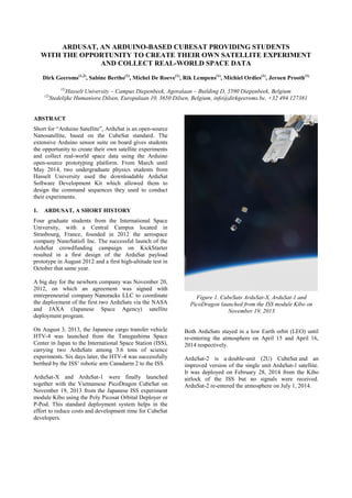
ArduSat-X and ArduSat-1 were finally launched
together with the Vietnamese PicoDragon CubeSat on
November 19, 2013 from the Japanese ISS experiment
module Kibo using the Poly Picosat Orbital Deployer or
P-Pod. This standard deployment system helps in the
effort to reduce costs and development time for CubeSat
developers.
Figure 1. CubeSats ArduSat-X, ArduSat-1 and
PicoDragon launched from the ISS module Kibo on
November 19, 2013
Both ArduSats stayed in a low Earth orbit (LEO) until
re-entering the atmosphere on April 15 and April 16,
2014 respectively.
ArduSat-2 is a double-unit (2U) CubeSat and an
improved version of the single unit ArduSat-1 satellite.
It was deployed on February 28, 2014 from the Kibo
airlock of the ISS but no signals were received.
ArduSat-2 re-entered the atmosphere on July 1, 2014.
2. 2. ARDUSAT UNCOVERED
ArduSat-X and ArduSat-1 are two single unit (1U)
CubeSats, with sides of 10 cm and a total mass of
approximately 1 kilogram. The tiny spacecraft’s
structure and power subsystems are based on the
CubeSat standard, an open-source specification created
in 1999 which defines a standard platform for low-cost
space research. Both satellites carry roughly 20 sensors,
including an optical spectrometer and a camera. The
overall architecture is shown in Fig. 2.
Figure 2. Architecture of a single unit ArduSat
The brain of the ArduSat-1 is the ArduSat Payload
Processor Module (ASPPM), represented in Fig. 3. It
features one supervisor processor consisting of an
ATmega2561 (similar to an Arduino Mega) plus 16
processor nodes each running an ATmega328P just like
an Arduino Uno.
Figure 3. The ArduSat Payload Processor Module
The role of the supervisor is to provide mass storage on
the Micro SD card for all processor nodes; power down
any nodes not in use; receive new sketches to execute
on nodes, and send them to the appropriate node via the
serial connection; provide debug information on the
serial debug console; and monitor power consumption
on the 5 V and 3.3 V rails. The processor nodes are
dedicated to computing the experiments, each on one
node.
To communicate with the ground, ArduSat is equipped
with a half-duplex UHF transceiver, operating in the
435-438 MHz amateur radio satellite band.
3. CODING FOR SPACE
The starting point for talking to sensors is Arduino, an
open-source electronics prototyping platform.
The Arduino programming environment is easy to use
for beginners, yet flexible enough for advanced users. It
is based on the Processing programming environment
and can be expanded through C++ libraries.
Open-source technology made it possible to enhance
Arduino’s baseline Integrated Development
Environment (IDE) with the ArduSat Software
Development Kit (SDK), available for download on
GitHub since May 2013.
Undergraduate physics students from Hasselt University
used an Arduino Uno to upload their code because the
processor nodes of the ASPPM in the ArduSat run a
similar microcontroller. To test the sensors all together,
a little demo CubeSat has been built using K’NEX, as
can be seen in Fig. 4 and Fig. 5.
The whole idea behind the working process is to create
code; submit code for review via email or through
ArduSat’s website; do code testing on a development
satellite; upload the program to the satellite; download
the resulting data from the satellite; and examine the
gathered data.
4. TESTING THE SENSOR SUITE
Because of the prototype nature of ArduSats-X/1 and
the failure of ArduSat-2, the code has never been
uploaded to the satellites. Nevertheless, as-if
experiments have been carried out on a test satellite
showing that the results obtained from the different
electronic devices aboard are reliable and ready to be
carried out in space.
Seven sensors of the ArduSat sensor suite have been
tested, the first six of them exactly the same as those in
the original ArduSat sensor suite.
3. Figure 4. Side view of K’NEX CubeSat
Figure 5. Top view of K'NEX CubeSat
4.1. Luminosity sensor (TSL2561)
Illuminance or ambient light level is a very complex
measurement to make because it involves both the
human eye’s response to color – i.e. frequency – and the
concentration of that light. The TSL2561 manufactured
by AMS-TAOS is not a true luxmeter, but rather a light-
to-digital converter that transforms light intensity to a
digital signal.
The device combines one broadband photodiode (visible
plus infrared) and one infrared-responding photodiode
on a single integrated circuit. Two integrating analog-to-
digital converters (ADCs) convert the photodiode
currents to a digital output that represents the irradiance
measured on each channel. This digital output is sent to
a microprocessor where illuminance in lux is derived
using an empirical formula to approximate the human
eye response. This makes the TSL2561 far superior to
simpler photoresistors and photodiodes for illumination
measurement.
The human eye has a huge dynamic range, far more
than most electronic sensors. Real-world conditions can
range from 0.0001 lux in starlight, to over 100,000 lux
in direct sunlight. The TSL2561 has features that allow
it to handle this huge dynamic range. These settings are
similar to a camera; one can change both the sensitivity,
which is like an ASA film rating, and the integration
time, which is like the shutter speed. Like a camera, you
can balance those measurements for the best results.
Illuminance values of a white LED measured by the
TSL2561 were compared to values obtained by a
Vernier Light Sensor giving percent differences of
about 6 %.
4.2. Three-axis accelerometer (ADXL345)
The ADXL345 from Analog Devices is a small, thin,
ultralow power, 3-axis accelerometer with high
resolution (13-bit) measurement at up to ±16 g. Digital
output data is accessible through an I²C digital interface.
The device measures the static acceleration of gravity in
tilt-sensing applications, as well as dynamic
acceleration resulting from motion or shock. Its high
resolution of 3.9 mg/LSB enables measurement of
inclination changes less than 1.0°. Several special
sensing functions are provided. Activity and inactivity
sensing detect the presence or lack of motion by
comparing the acceleration on any axis with user-set
thresholds. Tap sensing detects single and double taps in
any direction. Free-fall sensing detects if the device is
falling.
To test the accelerometer, the K’NEX CubeSat was put
in free-fall and used as a simple pendulum (Fig. 6),
giving percent errors of approximately 6% for the
theoretical period of the pendulum.
4.3. Digital 3-axis gyroscope (ITG-3200)
The ITG-3200 from InvenSense is a triple-axis Micro-
Electro-Mechanical Systems (MEMS) gyro integrated
circuit.
The device features digital-output X-, Y-, and Z-axis
angular rate sensors or gyros on a single chip with a
sensitivity of 14.375 LSBs per °/sec and a full-scale
range of ±2000 °/sec as well as a fast mode I²C interface
up to 400 kHz. Three integrated 16-bit ADCs provide
simultaneous sampling.
To test the gyroscope, the K’NEX CubeSat was put on a
turning plate (Fig. 7) rotating at a constant angular
velocity. Measured Z-axis values corresponded to
chronometer obtained data with percent differences of
about 11 %.
4. Figure 6. Experimental setup to test the 3-axis
accelerometer
Figure 7. Experimental setup to test the gyro
4.4. Digital temperature sensor (TMP102)
The TMP102 device from Texas Instruments is a silicon
bandgap digital temperature sensor, offering an
accuracy of ±0.5 °C. The device is specified for
operation over a temperature range of -40 °C to 125 °C.
Communication with the TMP102 is achieved through a
two-wire serial I²C interface.
A temperature experiment was run on the “AS-IF”
development satellite, located in Paris, France. A hot
and cold cycle were executed in a clean room testing
environment that acts as if it is a real satellite.
4.5. Digital 3-axis magnetometer (MAG3110)
Freescale’s Xtrinsic MAG3110 is a small, low-power,
digital 3-axis magnetometer. The device measures the
three components of the local magnetic field which will
be the sum of the geomagnetic field and the magnetic
field created by components on the circuit board. The
MAG3110 has a full scale range of ±1000 μT, features a
fast mode standard I2
C serial interface up to 400 kHz in
fast mode and is guaranteed to operate over the
extended temperature range of -40 °C to +85 °C.
Components of magnetic field measured by the
MAG3110 were compared to values obtained by a
Vernier Magnetic Field Sensor giving percent
differences of only 3 %.
4.6. Infrared temperature sensor (MLX90614)
The MLX90614 manufactured by Melexis is an infrared
thermometer for non-contact temperature
measurements. The device is factory calibrated in wide
temperature ranges: -40 to 125 ˚C for the ambient
temperature and -70 to 382.2 ˚C for the object
temperature.
An optical filter (long-wave pass) that cuts off the
visible and near infra-red radiant flux is integrated in the
package to provide ambient and sunlight immunity. The
wavelength pass band of this optical filter is from 5.5
till 14 µm.
A heat plate has been used to compare values obtained
by the MLX90614 with those of an Agilent multimeter,
resulting in percent differences of 6 %.
4.7. Geiger counter tube (SEN-11345)
Instead of the LND716 gamma detector from the
original ArduSat sensor suite, the USB powered
SparkFun Geiger counter SEN-11345 has been used to
detect ionizing radiation. One of the main reasons to opt
for the latter sensor is the fact that the SEN-11345 itself
is equipped with an ATMega328 which can be
programmed very easily.
Radiation from a cobalt-60 source measured by a
Vernier Digital Radiation Monitor gave percentage
differences of 6 % compared to values obtained by the
SEN-11345 sensor.
5. 5. UPLOADING TO SPACE
By the time students had to present their results at
Hasselt University, a new satellite named Lemur-1 had
been launched on June 19, 2014.
Lemur-1 is a triple-unit (3U) CubeSat built by Spire, the
new name for company NanoSatisfi since July 2014.
The satellite was deployed from the Italian UniSat 6,
which in turn was launched aboard a Dnepr launch
vehicle operated by Kosmotras. Lemur-1 is in a sun-
synchronous low Earth polar orbit with a more elliptical
shape compared to the formerly launched ArduSats.
The satellite’s primary mission is a technology
demonstration of several science payloads. In addition
to technology demonstration, Lemur-1 carries two
Earth-observation payloads, i.e. firstly an electro-optical
imaging system operating in the visible band with a
ground resolution of approximately 5 m and secondly a
low-resolution IR imaging system with an approximate
ground resolution of 1 km.
Although Lemur-1 has been successful sending data
from temperature sensors and the magnetometer, no
uploads from student experiments have been
established.
In April 2015, Spire successfully tested the education
payload on a high altitude balloon launch. The company
will have several satellites launched by the end of 2015,
eventually allowing students to run their experiments.
These satellites will head for higher orbits, where it is
estimated that the payload computers will be able to
operate for 8-12 months before radiation damage
becomes a factor.
6. CONCLUSIONS
This manuscript describes a project carried out by two
undergraduate physics students during a time period of
15 days spread across 10 weeks. Like a previous project
at Hasselt University [1], it shows that in this short
amount of time it is possible to write and test valuable
code ready for upload to a satellite in a low Earth orbit.
The open-source platform Arduino was the base of this
project and once again proved to be very student
friendly [2].
Unfortunately, so far it has not been possible to upload
the code to one of Spire’s satellites. Depending on the
level of sponsorship, contributors will have access to up
to an entire week of time on the satellite to run
applications. Nevertheless, experiments being carried
out on a test satellite show that the results obtained from
the different electronic devices are reliable and ready to
be carried out in space.
7. ACKNOWLEDGEMENTS
Both students and staff of Hasselt University involved
in this project wish to thank Nick Allain and Sunny
Washington of Spire for their support during the
programming process. We are especially indebted to
J.F. Omhover for his very valuable commenting the
code while being carried out on the development
satellite.
8. REFERENCES
[1] Joris, T. et al. (2013). Data Logging a Water Rocket
with Arduino. In Proc. ‘21st ESA Symposium on
European Rocket and Balloon Programmes and Related
Research’, Thun, Switzerland, 9-13 June 2013, ESA
SP-721, ESA Publications Division, European Space
Agency, Noordwijk, The Netherlands, pp. 201-205.
[2] de Schrijver, E. & Geeroms, D. (2011). A Novel
Approach to Hands-On Space Education Outreach for
Secondary School Students. In Proc. ‘20th ESA
Symposium on European Rocket and Balloon
Programmes and Related Research’, Hyères, France,
22-26 May 2011, ESA SP-700, ESA Publications
Division, European Space Agency, Noordwijk, The
Netherlands, pp. 249- 252.