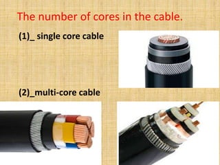
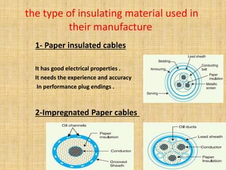
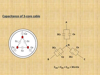
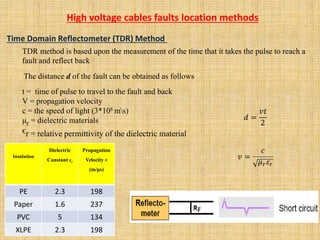
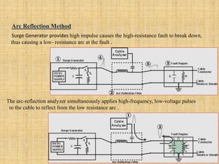
University of Turkish Aeronautical Association
Electric and Electronic Engineering Department
EEE 589 SPECIAL TOPICS IN ELECTRIC & ELECTRONIC ENGINEERING
Presented by:
Layth Faeq & Mahmood Natiq
Supervisor :
Dr. Ibrahim Mahariq
Fall -2016
Contents
Introduction
Advantages and disadvantages of cables
Construction of cables
Classification of cables
Calculation of high voltage cable parameters
Power losses and capacity amperage losses
Extension of underground cables
Types of cable faults
High voltage cables faults location methods
conclusion
Introduction
Underground cables is one of the means used for the
transmission and distribution of electric power in addition to the
overhead lines.
Where these cables are placed ?
Directly buried underground Placed inside the underground
tracks
Placed inside the
underground ducts.
these cables are considered more safer than overhead lines, where the
probability of touching people or birds or animals or small metal objects with
conductors carrying voltage electrode to be very rare .
Advantages & Disadvantages
Advantages
Better general appearance
Less liable to damage through storms or lighting
Low maintenance cost
Less chances of faults
Small voltage drops
Disadvantages
The major drawback is that they have greater installation cost and
introduce insulation problems at high voltages compared with
equivalent overhead system.
the general construction of a 3-conductor cable. The
various parts of cable are :
1-copper conductor
2- Inner semi-conductive
3-XLPE insulation
4-Outer semi-conductive
5-Semi-conductive tape
6-Copper tape screen
7-filling
8-PVC separation sheath
9-Galvanized double steel tape
10-PVC outer sheath
Classification of cables according to:-
1 - number of cores in the cable .
2 - the type of insulating materials used in their manufacturing.
.3 - the voltage for which they are manufactured
The number of cores in the cable.
(1)_ single core cable
(2)_multi-core cable
the type of insulating material used in
their manufacture
1- Paper insulated cables
It has good electrical properties .
It needs the experience and accuracy
In performance plug endings .
2-Impregnated Paper cables
3-ethylene propylene Rubber
Easier to installMore flexible -
Better flame resistance
Increased thermal stability
4-Polyvinyl chloride (PVC)
It is cheap .
It considered the best choice until 3.3 kv .
It is inappropriate for high voltage .
5- Cross Linked poly- ethylene (XLPE)
1-This material has temperature range beyond 70-90
2-This material good insulating properties
the voltage for which they are
manufactured
Low-tension (L.T.) Cables......upto 1000V
Thickness of insulating = 1.5 mm
high-tension (H.T.) Cables.... 11KV
Thickness of insulating = (4-5) mm
super-tension (S.T.) Cables.. 33KV
Thickness of insulating = (8) mm
Extra-high tension(E.H.T) Cables.. 66KV
Thickness of insulating = (16) mm
Extra-super voltage Cables.. 132KV
Thickness of insulating = (23) mm
Conductor resistance of A single-core cables
A ᵨ
ᵨ=Material with resistivity
L = Length
A= Cross – sectional area
R=
ᵨ L
A
(ohm)
Where
ᵨcu
(ohm ∕ m)
(m)
(m2)
= 1,724* 10-8
ᵨAl = 2,803* 10-8
Calculation of high voltage cable parameters
Insulation resistance of A single –core cables
Radius of conductor=r1
Radius of sheath=r2
Thickness of layer=dx
R =
ᵨ
2π L
ln
r1
r2
(ohm)
This shows that insulation resistance of a cable is inversely proportional to its length. In
other word, if the cable length increases , its insulation resistance decreases and vice-versa
Capacitance of single core cable
Conductor diameter=d
Inner sheath diameter=D
The charge per meter =Q coulombs
the relative permittivity of the insulation=ϵr
Permittivity=ϵ0
Vph=∫ E.dx =∫
C=
IC= ωcVph (Amper)
Where ϵ=ϵ0 ϵr2 πϵ
ln
D
d
Q
Vph
D∕2
d∕2
Q
2 πϵ x
.dx =
d∕2
D∕2
Q
2 πϵ
ln
d
D (Volt)
= (F∕m)
Where ω=2π F
Capacitance of 3-core cable
CcCc
Cc
Ce
CeCe
A
N
B C
Ce3Cc
3Cc
Ce 3Cc
Ce
CAN = CBN = CCN = 3Cc+Ce
Electrical field intensity
Vph
X.ln
r2
r1
Emax=
Vph
r1.ln
r1
r2
Emin=
Vph
r2.ln
r1
r2
E= (volt∕ m)
(volt∕ m)
E=
Q
2πϵ0ϵr X
(volt∕ m)
Q=
2πϵ0ϵr Vph
ln
r1
r2
(coulombs)
Wd
I2 R
T2
T3
R.λ1nl2
R.λ2nl2
T4
T1
Power losses and capacity amperage losses
Δθ = ( I2 R+0.5wd ) T1+ ( I2R (1+λ1)+ wd ) nT2 + ( I2 R (1+λ1+λ2) + wd) n( T3+T4)
I ={ Δθ – wd [ 0.5T1 + n (T2+T3+T4)
RT1 + nR ( 1+λ1) T2 + nR (1+λ1+λ2)(T3+T4)
}
1/2
where Thermal resistancesT1,T2,T3,T4 =
wd= loss in insulation
n= number of conductors
λ1= loss between conductor and metallic sheath
λ2= loss between conductor and armour
Extension of underground cables
20 cm20 cm
60 cm80 cm
30 cm
10 cm
20cm
5 cm
20 cm
20 cm
30cm
5 cm
110 cm
River sand
Cutting
concrete
Soft soil
Natural soil
without stones
Warning tape
Natural soil
slabbing
High voltage Cable Joint
1 2 3 4
5 6 7 8
9 10 11 12
Types of cable faults
the following are the faults most likely
to occur underground cables.
1) open circuit fault
2) short circuit fault
Time Domain Reflectometer (TDR) Method
TDR method is based upon the measurement of the time that it takes the pulse to reach a
fault and reflect back
The distance d of the fault can be obtained as follows
t = time of pulse to travel to the fault and back
V = propagation velocity
c = the speed of light (3*108 ms)
μr = dielectric materials
ϵr = relative permittivity of the dielectric material
Propagation
Velocity v
(m/μs)
Dielectric
Constant εr
Insulation
1982.3PE
2371.6Paper
1345PVC
1982.3XLPE
High voltage cables faults location methods
For fully understand the principle, the equivalent circuit of a transmission line
Characteristic Impedance of transmission line
Z o =
LR + jωL
G + jωC
=
C
ᵨr =Reflection coefficient
ZL =0 at short circuit
ᵨr =
ZL – Z0
ZL + Z0
Vr= -V
s
Arc Reflection Method
The arc-reflection analyzer simultaneously applies high-frequency, low-voltage pulses
to the cable to reflect from the low resistance arc .
Surge Generator provides high impulse causes the high-resistance fault to break down,
.thus causing a low- resistance arc at the fault
conclusion
Thank you for
listening

High voltage underground cables

  • 1.
    University of TurkishAeronautical Association Electric and Electronic Engineering Department EEE 589 SPECIAL TOPICS IN ELECTRIC & ELECTRONIC ENGINEERING Presented by: Layth Faeq & Mahmood Natiq Supervisor : Dr. Ibrahim Mahariq Fall -2016
  • 2.
    Contents Introduction Advantages and disadvantagesof cables Construction of cables Classification of cables Calculation of high voltage cable parameters Power losses and capacity amperage losses Extension of underground cables Types of cable faults High voltage cables faults location methods conclusion
  • 3.
    Introduction Underground cables isone of the means used for the transmission and distribution of electric power in addition to the overhead lines.
  • 4.
    Where these cablesare placed ? Directly buried underground Placed inside the underground tracks Placed inside the underground ducts.
  • 5.
    these cables areconsidered more safer than overhead lines, where the probability of touching people or birds or animals or small metal objects with conductors carrying voltage electrode to be very rare .
  • 6.
    Advantages & Disadvantages Advantages Bettergeneral appearance Less liable to damage through storms or lighting Low maintenance cost Less chances of faults Small voltage drops Disadvantages The major drawback is that they have greater installation cost and introduce insulation problems at high voltages compared with equivalent overhead system.
  • 7.
    the general constructionof a 3-conductor cable. The various parts of cable are : 1-copper conductor 2- Inner semi-conductive 3-XLPE insulation 4-Outer semi-conductive 5-Semi-conductive tape 6-Copper tape screen 7-filling 8-PVC separation sheath 9-Galvanized double steel tape 10-PVC outer sheath
  • 8.
    Classification of cablesaccording to:- 1 - number of cores in the cable . 2 - the type of insulating materials used in their manufacturing. .3 - the voltage for which they are manufactured
  • 9.
    The number ofcores in the cable. (1)_ single core cable (2)_multi-core cable
  • 10.
    the type ofinsulating material used in their manufacture 1- Paper insulated cables It has good electrical properties . It needs the experience and accuracy In performance plug endings . 2-Impregnated Paper cables
  • 11.
    3-ethylene propylene Rubber Easierto installMore flexible - Better flame resistance Increased thermal stability 4-Polyvinyl chloride (PVC) It is cheap . It considered the best choice until 3.3 kv . It is inappropriate for high voltage .
  • 12.
    5- Cross Linkedpoly- ethylene (XLPE) 1-This material has temperature range beyond 70-90 2-This material good insulating properties
  • 13.
    the voltage forwhich they are manufactured Low-tension (L.T.) Cables......upto 1000V Thickness of insulating = 1.5 mm high-tension (H.T.) Cables.... 11KV Thickness of insulating = (4-5) mm super-tension (S.T.) Cables.. 33KV Thickness of insulating = (8) mm Extra-high tension(E.H.T) Cables.. 66KV Thickness of insulating = (16) mm Extra-super voltage Cables.. 132KV Thickness of insulating = (23) mm
  • 14.
    Conductor resistance ofA single-core cables A ᵨ ᵨ=Material with resistivity L = Length A= Cross – sectional area R= ᵨ L A (ohm) Where ᵨcu (ohm ∕ m) (m) (m2) = 1,724* 10-8 ᵨAl = 2,803* 10-8 Calculation of high voltage cable parameters
  • 15.
    Insulation resistance ofA single –core cables Radius of conductor=r1 Radius of sheath=r2 Thickness of layer=dx R = ᵨ 2π L ln r1 r2 (ohm) This shows that insulation resistance of a cable is inversely proportional to its length. In other word, if the cable length increases , its insulation resistance decreases and vice-versa
  • 16.
    Capacitance of singlecore cable Conductor diameter=d Inner sheath diameter=D The charge per meter =Q coulombs the relative permittivity of the insulation=ϵr Permittivity=ϵ0 Vph=∫ E.dx =∫ C= IC= ωcVph (Amper) Where ϵ=ϵ0 ϵr2 πϵ ln D d Q Vph D∕2 d∕2 Q 2 πϵ x .dx = d∕2 D∕2 Q 2 πϵ ln d D (Volt) = (F∕m) Where ω=2π F
  • 17.
    Capacitance of 3-corecable CcCc Cc Ce CeCe A N B C Ce3Cc 3Cc Ce 3Cc Ce CAN = CBN = CCN = 3Cc+Ce
  • 18.
    Electrical field intensity Vph X.ln r2 r1 Emax= Vph r1.ln r1 r2 Emin= Vph r2.ln r1 r2 E=(volt∕ m) (volt∕ m) E= Q 2πϵ0ϵr X (volt∕ m) Q= 2πϵ0ϵr Vph ln r1 r2 (coulombs)
  • 19.
    Wd I2 R T2 T3 R.λ1nl2 R.λ2nl2 T4 T1 Power lossesand capacity amperage losses Δθ = ( I2 R+0.5wd ) T1+ ( I2R (1+λ1)+ wd ) nT2 + ( I2 R (1+λ1+λ2) + wd) n( T3+T4) I ={ Δθ – wd [ 0.5T1 + n (T2+T3+T4) RT1 + nR ( 1+λ1) T2 + nR (1+λ1+λ2)(T3+T4) } 1/2 where Thermal resistancesT1,T2,T3,T4 = wd= loss in insulation n= number of conductors λ1= loss between conductor and metallic sheath λ2= loss between conductor and armour
  • 20.
    Extension of undergroundcables 20 cm20 cm 60 cm80 cm 30 cm 10 cm 20cm 5 cm 20 cm 20 cm 30cm 5 cm 110 cm River sand Cutting concrete Soft soil Natural soil without stones Warning tape Natural soil slabbing
  • 23.
    High voltage CableJoint 1 2 3 4 5 6 7 8 9 10 11 12
  • 24.
    Types of cablefaults the following are the faults most likely to occur underground cables. 1) open circuit fault 2) short circuit fault
  • 25.
    Time Domain Reflectometer(TDR) Method TDR method is based upon the measurement of the time that it takes the pulse to reach a fault and reflect back The distance d of the fault can be obtained as follows t = time of pulse to travel to the fault and back V = propagation velocity c = the speed of light (3*108 ms) μr = dielectric materials ϵr = relative permittivity of the dielectric material Propagation Velocity v (m/μs) Dielectric Constant εr Insulation 1982.3PE 2371.6Paper 1345PVC 1982.3XLPE High voltage cables faults location methods
  • 26.
    For fully understandthe principle, the equivalent circuit of a transmission line Characteristic Impedance of transmission line Z o = LR + jωL G + jωC = C ᵨr =Reflection coefficient ZL =0 at short circuit ᵨr = ZL – Z0 ZL + Z0 Vr= -V s
  • 27.
    Arc Reflection Method Thearc-reflection analyzer simultaneously applies high-frequency, low-voltage pulses to the cable to reflect from the low resistance arc . Surge Generator provides high impulse causes the high-resistance fault to break down, .thus causing a low- resistance arc at the fault
  • 28.
  • 29.