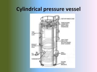
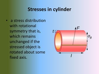
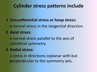
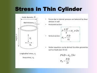
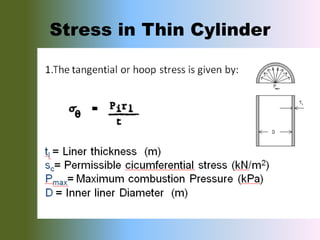
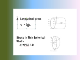
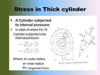
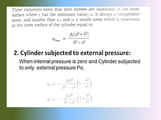
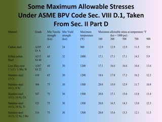
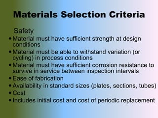
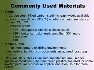
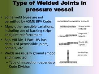
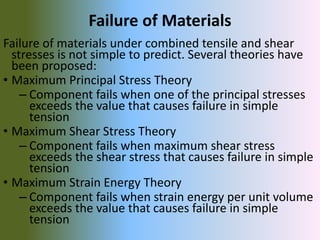
(06-12-2k17)
MNS UTE MULTAN
Presented By ; Abdul Hannan
Muhhamad Asif
Presented To; Eng : Muhammad Aon Ali
Topic ; pressure vessels &
stresses produces in it
(06-12-2k17)
(2016-2020)
(semester 3rd)
Department of Mechanical Engineering
Technology
Cylinder
• Cylinder is a mechanical device used for
storing ,receiving processing the fluid.
Cylinder may be:
1. Pressure vessel
2. Storage vessel
3. Pipe
4. Engine cylinder
Pressure vessel
• Pressure vessel are
container or pipe line for
storing , receiving or
carrying the fluids under a
pressure.
1 Unfired pressure vessel
are: storage vessel
,reaction vessel , heat
exchanger , evaporator
2 Other: Steam boiler,
nuclear pressure vessel
Manufacturing Process
• Forming
• Pressing
• Spinning
• Bending
• Welding
• Post weld heat treatment (PWHT)
• Assembling
• Painting
Shape of Pressure vessel
Main components
• Shell
• Head
• Nozzle
• Support
Vessel Orientation
• Usually vertical
– Easier to distribute fluids
across a smaller cross section
– Smaller plot space
• Reasons for using horizontal
vessels
– To promote phase separation
• Increased cross section =
lower vertical velocity =
less entrainment
• Decanters, settling tanks,
separators, flash vessels
– To allow internals to be pulled
for cleaning
• Heat exchangers
Common types of P.V
1 Process pressure vessels:
In which specific process being done.
2 Heat exchanger pressure vessels:
Those where heat energy exchanges with
energy optimization.
Types of
Process pressure vessels
1 Column pressure vessel
2 Reactor pressure vessel
3 Gravity separator pressure vessel
4 Drums
Column pressure vessel
Reactor pressure vessel
Gravity separator pressure vessel
Drums
Drums
Geometric based types
1 Spherical pressure vessel
2 Cylindrical pressure vessel
Spherical pressure vessel
layout
Spherical separator schematic
Cylindrical pressure vessel
Applications
• Industrial compressed air receiver.
• Domestic hot water tank.
• Diving cylinder.
• Recompression camber.
• Distillation tower.
• Oil refineries and petrochemical plant.
• Nuclear reactor .
• Rail road industry.
• Storage for gasses and liquids .
Stresses in cylinder
• a stress distribution
with rotational
symmetry that is,
which remains
unchanged if the
stressed object is
rotated about some
fixed axis.
Cylinder stress patterns include
1 Circumferential stress or hoop stress:
a normal stress in the tangential direction.
2 Axial stress:
a normal stress parallel to the axis of
cylindrical symmetry.
3 Radial stress:
a stress in directions coplanar with but
perpendicular to the symmetry axis.
Stress in Thin Cylinder
Stress in Thick cylinder
Some Maximum Allowable Stresses
Under ASME BPV Code Sec. VIII D.1, Taken
From Sec. II Part D
Material Grade Min Tensile Min Yield Maximum Maximum allowable stress at temperature F
strength strength temperature (ksi = 1000 psi)
(ksi) (ksi) (ºF) 100 300 500 700 900
Carbon steel A285 45 24 900 12.9 12.9 12.9 11.5 5.9
Gr A
Killed carbon A515 60 32 1000 17.1 17.1 17.1 14.3 5.9
Steel Gr 60
Low alloy steel A387 60 30 1200 17.1 16.6 16.6 16.6 13.6
1 ¼ Cr, ½ Mo, Si Gr 22
Stainless steel 410 65 30 1200 18.6 17.8 17.2 16.2 12.3
13 Cr
Stainless steel 304 75 30 1500 20.0 15.0 12.9 11.7 10.8
18 Cr, 8 Ni
Stainless steel 347 75 30 1500 20.0 17.1 15.0 13.8 13.4
18 Cr, 10 Ni, Cb
Stainless steel 321 75 30 1500 20.0 16.5 14.3 13.0 12.3
18 Cr, 10 Ni, Ti
Stainless steel 316 75 30 1500 20.0 15.6 13.3 12.1 11.5
16 Cr, 12 Ni, 2 Mo
Materials Selection Criteria
Safety
Material must have sufficient strength at design
conditions
Material must be able to withstand variation (or
cycling) in process conditions
Material must have sufficient corrosion resistance to
survive in service between inspection intervals
Ease of fabrication
Availability in standard sizes (plates, sections, tubes)
Cost
Includes initial cost and cost of periodic replacement
Commonly Used Materials
• Steels
– Carbon steel, Killed carbon steel – cheap, widely available
– Low chrome alloys (<9% Cr) – better corrosion resistance
than CS, KCS
– Stainless steels:
• 304 – cheapest austenitic stainless steel
• 316 – better corrosion resistance than 304, more
expensive
• 410
• Nickel Alloys
– high temperature oxidizing environments
– expensive, but high corrosion resistance, used for strong
acids
• Other metals such as aluminum and titanium are used for
special applications. Fiber reinforced plastics are used for some
low temperature & pressure applications. See Ch 7 for more
details
Type of Welded Joints in
pressure vessel
• Some weld types are not
permitted by ASME BPV Code
• Many other possible variations,
including use of backing strips
and joint reinforcement
• Sec. VIII Div. 1 Part UW has
details of permissible joints,
corners, etc.
• Welds are usually ground smooth
and inspected
– Type of inspection depends on
Code Division
Failure of Materials
Failure of materials under combined tensile and shear
stresses is not simple to predict. Several theories have
been proposed:
• Maximum Principal Stress Theory
– Component fails when one of the principal stresses
exceeds the value that causes failure in simple
tension
• Maximum Shear Stress Theory
– Component fails when maximum shear stress
exceeds the shear stress that causes failure in simple
tension
• Maximum Strain Energy Theory
– Component fails when strain energy per unit volume
exceeds the value that causes failure in simple
tension
END

Pressure vessels

  • 1.
  • 2.
    MNS UTE MULTAN PresentedBy ; Abdul Hannan Muhhamad Asif Presented To; Eng : Muhammad Aon Ali Topic ; pressure vessels & stresses produces in it (06-12-2k17) (2016-2020) (semester 3rd) Department of Mechanical Engineering Technology
  • 3.
    Cylinder • Cylinder isa mechanical device used for storing ,receiving processing the fluid. Cylinder may be: 1. Pressure vessel 2. Storage vessel 3. Pipe 4. Engine cylinder
  • 4.
    Pressure vessel • Pressurevessel are container or pipe line for storing , receiving or carrying the fluids under a pressure. 1 Unfired pressure vessel are: storage vessel ,reaction vessel , heat exchanger , evaporator 2 Other: Steam boiler, nuclear pressure vessel
  • 5.
    Manufacturing Process • Forming •Pressing • Spinning • Bending • Welding • Post weld heat treatment (PWHT) • Assembling • Painting
  • 6.
    Shape of Pressurevessel Main components • Shell • Head • Nozzle • Support
  • 8.
    Vessel Orientation • Usuallyvertical – Easier to distribute fluids across a smaller cross section – Smaller plot space • Reasons for using horizontal vessels – To promote phase separation • Increased cross section = lower vertical velocity = less entrainment • Decanters, settling tanks, separators, flash vessels – To allow internals to be pulled for cleaning • Heat exchangers
  • 9.
    Common types ofP.V 1 Process pressure vessels: In which specific process being done. 2 Heat exchanger pressure vessels: Those where heat energy exchanges with energy optimization.
  • 10.
    Types of Process pressurevessels 1 Column pressure vessel 2 Reactor pressure vessel 3 Gravity separator pressure vessel 4 Drums
  • 11.
  • 12.
  • 13.
  • 14.
  • 15.
  • 16.
    Geometric based types 1Spherical pressure vessel 2 Cylindrical pressure vessel
  • 17.
  • 18.
  • 19.
  • 21.
  • 22.
  • 23.
    Applications • Industrial compressedair receiver. • Domestic hot water tank. • Diving cylinder. • Recompression camber. • Distillation tower. • Oil refineries and petrochemical plant. • Nuclear reactor . • Rail road industry. • Storage for gasses and liquids .
  • 24.
    Stresses in cylinder •a stress distribution with rotational symmetry that is, which remains unchanged if the stressed object is rotated about some fixed axis.
  • 25.
    Cylinder stress patternsinclude 1 Circumferential stress or hoop stress: a normal stress in the tangential direction. 2 Axial stress: a normal stress parallel to the axis of cylindrical symmetry. 3 Radial stress: a stress in directions coplanar with but perpendicular to the symmetry axis.
  • 26.
  • 27.
  • 29.
  • 31.
    Some Maximum AllowableStresses Under ASME BPV Code Sec. VIII D.1, Taken From Sec. II Part D Material Grade Min Tensile Min Yield Maximum Maximum allowable stress at temperature F strength strength temperature (ksi = 1000 psi) (ksi) (ksi) (ºF) 100 300 500 700 900 Carbon steel A285 45 24 900 12.9 12.9 12.9 11.5 5.9 Gr A Killed carbon A515 60 32 1000 17.1 17.1 17.1 14.3 5.9 Steel Gr 60 Low alloy steel A387 60 30 1200 17.1 16.6 16.6 16.6 13.6 1 ¼ Cr, ½ Mo, Si Gr 22 Stainless steel 410 65 30 1200 18.6 17.8 17.2 16.2 12.3 13 Cr Stainless steel 304 75 30 1500 20.0 15.0 12.9 11.7 10.8 18 Cr, 8 Ni Stainless steel 347 75 30 1500 20.0 17.1 15.0 13.8 13.4 18 Cr, 10 Ni, Cb Stainless steel 321 75 30 1500 20.0 16.5 14.3 13.0 12.3 18 Cr, 10 Ni, Ti Stainless steel 316 75 30 1500 20.0 15.6 13.3 12.1 11.5 16 Cr, 12 Ni, 2 Mo
  • 32.
    Materials Selection Criteria Safety Materialmust have sufficient strength at design conditions Material must be able to withstand variation (or cycling) in process conditions Material must have sufficient corrosion resistance to survive in service between inspection intervals Ease of fabrication Availability in standard sizes (plates, sections, tubes) Cost Includes initial cost and cost of periodic replacement
  • 33.
    Commonly Used Materials •Steels – Carbon steel, Killed carbon steel – cheap, widely available – Low chrome alloys (<9% Cr) – better corrosion resistance than CS, KCS – Stainless steels: • 304 – cheapest austenitic stainless steel • 316 – better corrosion resistance than 304, more expensive • 410 • Nickel Alloys – high temperature oxidizing environments – expensive, but high corrosion resistance, used for strong acids • Other metals such as aluminum and titanium are used for special applications. Fiber reinforced plastics are used for some low temperature & pressure applications. See Ch 7 for more details
  • 34.
    Type of WeldedJoints in pressure vessel • Some weld types are not permitted by ASME BPV Code • Many other possible variations, including use of backing strips and joint reinforcement • Sec. VIII Div. 1 Part UW has details of permissible joints, corners, etc. • Welds are usually ground smooth and inspected – Type of inspection depends on Code Division
  • 35.
    Failure of Materials Failureof materials under combined tensile and shear stresses is not simple to predict. Several theories have been proposed: • Maximum Principal Stress Theory – Component fails when one of the principal stresses exceeds the value that causes failure in simple tension • Maximum Shear Stress Theory – Component fails when maximum shear stress exceeds the shear stress that causes failure in simple tension • Maximum Strain Energy Theory – Component fails when strain energy per unit volume exceeds the value that causes failure in simple tension
  • 36.