1. Definitions ofPressure Vessels
2. Typical Components of Pressure Vessels
3. Classification of Pressure Vessels
4. Uses of Pressure Vessels
5. ASME Codes Used for Pressure Vessels
6. Design Criteria
7. Comparison Of Pressure Vessels Designed Under
the Standard Codes
8. Non-Destructive Tests Performed On Pressure
Vessels
9. Leak- Testing Methods On Pressure Vessels
AGENDA
4.
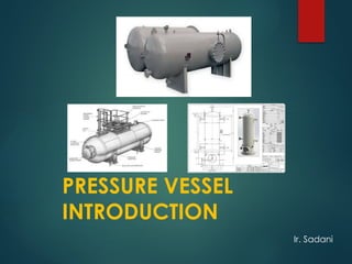
A pressurevessel is a closed container designed
to hold gases or liquids at a pressure substantially
different from the gauge pressure.
Pressure Vessels are defined in ASME Section
VIII, Div 1 introduction:
“ Pressure Vessels are containers for the
containment of pressure either external or internal.
The pressure may be obtained from an external
source, or by the application of heat from a direct
or indirect source, or any combination thereof.”
DEFINITION
5.
1. Cylindrical or
SphericalShell
2. Formed Heads
3. Blind Flanges, Cover
Plates, Flanges
4. Openings And
Nozzles
5. Supports
PRESSURE VESSEL COMPONENT
6.
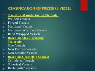
Based onManufacturing Methods:
1) Welded Vessels
2) Forged Vessels
3) Multiwall Vessels
4) Multiwall Wrapped Vessels
5) Band Wrapped Vessels
Based on Manufacturing
Materials:
1) Steel Vessels
2) Non Ferrous Vessels
3) Non Metallic Vessels
Based on Geometric Shapes:
1) Cylindrical Vessels
2) Spherical Vessels
3) Rectangular Vessels
CLASIFICATION OF PRESSURE VESSEL
7.
4) Combined Vessels
Based on Installation Methods:
1) Vertical Vessels
2) Horizontal Vessels
Based on Pressure-Bearing Situation:
1) Internal Pressure Vessels
2) External Pressure Vessels
Based on Wall Thickness:
1) Thin Wall Vessel
2) Thick Wall Vessel
Based on Technological Processes:
1) Reaction Vessel
2) Heat Exchanger Vessel
3) Separation Vessel
4) Storage Container Vessel
8.
Based onOperating Temperature:
1) Low Temperature Vessels(less than or equal to -20°C)(<=-40
F)
2) Normal Temperature Vessels(Between -20°C to 150°C)(-4o
F to 302o
F)
3) Medium Temperature Vessels(Between 150°C to 450°C)(302o
Fto842o
F)
4) High Temperature Vessels(more than or equal to 450°C)(>=842o
F)
Based on Design Pressure:
1) Low Pressure Vessels(0.1MPa to 1.6MPa)(14.5 psi to 232 psi)
2) Medium Pressure Vessels(1.6MPa to 10MPa)(232 psi to 1450.4 psi)
3) High Pressure Vessels(10MPa to 100MPa)(1450.4 psi to 14500.8 psi)
4) Ultra High Pressure Vessels(More than 100MPa) (> 14500.8 psi)
Based on Usage Mode:
1) Fixed Pressure Vessel
2) Mobile Pressure Vessel
9.
1) Industrial compressedair receivers
2) Domestic hot water storage tanks
3) Diving cylinders
4) Recompression chambers
5) Distillation towers
6) Autoclaves
7) Oil refineries and petrochemical plants
8) Nuclear reactor vessels
9) Pneumatic And Hydraulic Reservoirs
10) Storage vessels for liquified gases such
as ammonia, chlorine, propane, butane, and LPG.
USED OF PRESSURE VESSEL
10.
•ASME BPVC SectionII
Part A - Ferrous Material Specifications
Part B - Nonferrous Material Specifications
Part C - Specifications for Welding
Rods, Electrodes, and Filler Metals
Part D - Properties (Customary)
Part D - Properties (Metric)
•ASME BPVC Section V - Non destructive
Examination
PRESSURE VESSEL CODES
11.
•ASME Section VIII: Boiler and Pressure
Vessel Code (BPVC)
Division 1- Rules for Construction of Pressure
Vessels
Division 2 - Alternative Rules
Division 3 - Alternative Rules for Construction
of High Pressure Vessels
PRESSURE VESSEL CODES
12.
Selection OfThe Type Of Vessel:
i. The operating temperature and pressure.
ii. Function and location of the vessel.
iii. Nature of fluid.
iv. Necessary volume for storage or capacity for
processing
Design Loads
Materials
Allowable Stress
DESIGN CRITERIA
13.
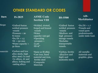
Item IS-2825 ASMECode
Section VIII
BS-5500
AD-
Merkblatter
Scope •Unfired fusion
welded pressure
vessels
•Pressure < 20
N/mm2
•Do/Di < 1.5
•Di > 150 mm
•Water capacity >
50 litres
•Welded, riveted,
forged and brazed
vessels
•Water
capacity>120 gal
•Operating
pressure >
15 psi
•Di>6”
•Unfired fusion
welded pressure
vessels
•Medium and
high pressure
storage vessels
•Excludes
transportable
vessels.
•Do/Di < 1.7
•Vessels and
vessel parts
predominantly
under static load.
materials •Carbon and low
alloy steels, high
alloy steel, Cu and
Cu alloys, Al and
alloys, bolting and
casting alloys
•Same as IS-2825
•Cast iron, lined
material cast iron,
ferritic steel
•Composite
Materials
•Carbon, ferritic
alloy(low and
high) and
austenitic steels
All metallic
materials and
graphite, glass.
OTHER STANDARD OR CODES
14.
Item IS-2825 ASMECode
Section VIII
BS-5500 AD-
Merkblatter
Design Maximum working Maximum pressure Maximum Based on
pressure pressure including at most severe pressure at permissible service
static head + 5% conditions most severe pressure
maximum working conditions
pressure.
Design Highest metal Actual metal Actual metal Highest
tempera- temperature expected temperature temperature temperature
ture under operating expected under expected under expected under
conditions operating conditions operating working conditions
conditions +
margin for
uncertainties
COMPARATION OF PRESSURE VESSEL
CODES OR STANDARD OTHERS
15.
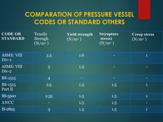
CODE OR
STANDARD
Tensile
Strengh
(N/m2 )
Yieldstrength
(N/m2 )
Sr(rupture
stress)
(N/m2 )
Creep stress
(N/m2 )
ASME: VIII
Div-1
3.5 1.6 - 1
ASME: VIII
Div-2
3 1.5 - -
BS-1515 4 - - -
BS-1515
Part II
2.5 1.5 1.5 1
BS-5500 2.35 1.5 1.3 1
ANCC - 1.5 1.5 -
IS-2825 3 1.5 1.5 1
COMPARATION OF PRESSURE VESSEL
CODES OR STANDARD OTHERS
16.
The five principlemethods of NDT used
are:
1. Visual testing (VT)
2. Penetrant testing (PT)
3. Magnetic particle testing (MT)
4. Ultrasonic testing (UT)
5. Radiographic testing (RT)
NDE ON PRESSURE VESSELS
17.
There are manydifferent methods for pressure
and leak testing in the field. Seven of these
are:
1. Hydrostatic testing
2. Pneumatic or gaseous-fluid testing
3. Combined pneumatic and hydrostatic
testing
4. Initial service testing
5. Vacuum testing
6. Static head testing
TEST PRESSURE OR LEAK TEST
18.
DESIGN OF PRESSUREVESSELS:-
Pressure Vessel is contain following main equipment.
SHELL
DISHED END [ D’END]
NOZZLES
MANWAYS
LUGS
SUPPORTS
19.
The thickness ofshell is depending upon the type of shell and
stresses. Generally Shell can be classified in 2 categories.
1. Cylindrical Shell
2. Spherical Shell
Stress can also classified in 2 categories.
1. Circumferential Stress
2. Longitudinal Stress
Thickness for Cylindrical Shell :-
Circumferential Stress
t = PR +C.A. OR P = SEt +
C.A.
SE - 0.6P R + 0.6t
Longitudinal Stress: -
t = PR +C.A. OR P = 2SEt + C.A.
2SE + 0.4P R - 0.4t
20.
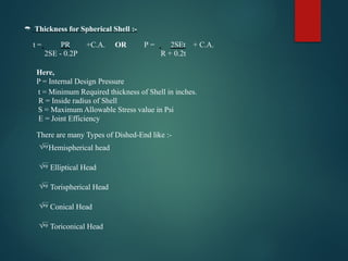
Thickness forSpherical Shell :-
t = PR +C.A. OR P = 2SEt + C.A.
2SE - 0.2P R + 0.2t
Here,
P = Internal Design Pressure
t = Minimum Required thickness of Shell in inches.
R = Inside radius of Shell
S = Maximum Allowable Stress value in Psi
E = Joint Efficiency
There are many Types of Dished-End like :-
Hemispherical head
Elliptical Head
Torispherical Head
Conical Head
Toriconical Head
21.
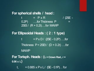
For spherical shells/ head:
t = P x R / (2SE -
0.2P) ….forThickness P =
2SEt / (R + 0.2t)….for MAWP
For Ellipsoidal Heads : ( 2 : 1 type)
t = Px D / (2SE - 0.2P) ….for
Thickness P= 2SEt / (D + 0.2t) ….for
MAWP
For Torisph. Heads : (L = Crown Rad., r =
0.06 x L)
t, = 0.885 x Px L/ (SE- 0.1P)… for
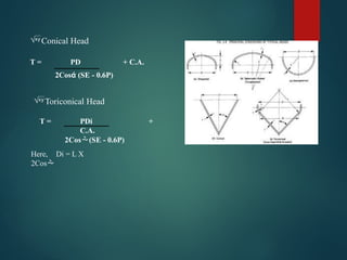
22.
T = PD+ C.A.
2Cosά (SE - 0.6P)
Conical Head
T = PDi +
C.A.
2Cos(SE - 0.6P)
Here, Di = L X
2Cos
Toriconical Head
GENERAL NOTE: Thisfigure illustrates a common nozzle configuration and is not
intended to prohibit other configurations permitted by the
Code.
NOTES:
(1) Includes consideration of these areas if Sn/Sv < 1.0 (both sides of centerline).
(2) This formula is applicable for a rectangular cross‐sectional element that falls
within the limits of reinforcement.
26.
1) ASME SectionVIII Div. 1 and 2.
2) Pressure vessels Hand Book edition 12.
3) Structure Analysis and Design of Process
Equipment
4) Google Search
REFRENCES


![DESIGN OF PRESSURE VESSELS:-
Pressure Vessel is contain following main equipment.
SHELL
DISHED END [ D’END]
NOZZLES
MANWAYS
LUGS
SUPPORTS](https://image.slidesharecdn.com/pressurevesselsintroduction1-250225160409-2d2d8578/85/engineeringpressurevesselsintroduction1-pptx-18-320.jpg)


![office final ppt [7760835] final update](https://cdn.slidesharecdn.com/ss_thumbnails/aba3fa8b-edf3-48e1-ba61-7fb4f65dc95a-160410081228-thumbnail.jpg?width=640&height=640&fit=bounds)