This document provides a summary of an Indian Standard code of practice for the design, fabrication, and erection of vertical mild steel cylindrical welded oil storage tanks. The standard covers general requirements, materials, permissible stresses, design considerations for foundations, bottom plates, shell plates, roofs, and floating roofs. It also addresses appurtenances and mountings, shop fabrication and inspection, site erection, site welding, radiographic inspection of shell joints, and testing of tanks. Tables and figures are provided to illustrate typical tank components and specifications. The standard aims to promote transparency and accountability in public works by making this safety information publicly available.
![Disclosure to Promote the Right To Information
Whereas the Parliament of India has set out to provide a practical regime of right to
information for citizens to secure access to information under the control of public authorities,
in order to promote transparency and accountability in the working of every public authority,
and whereas the attached publication of the Bureau of Indian Standards is of particular interest
to the public, particularly disadvantaged communities and those engaged in the pursuit of
education and knowledge, the attached public safety standard is made available to promote the
timely dissemination of this information in an accurate manner to the public.
इंटरनेट मानक
“!ान $ एक न' भारत का +नम-ण”
Satyanarayan Gangaram Pitroda
“Invent a New India Using Knowledge”
“प0रा1 को छोड न' 5 तरफ”
Jawaharlal Nehru
“Step Out From the Old to the New”
“जान1 का अ+धकार, जी1 का अ+धकार”
Mazdoor Kisan Shakti Sangathan
“The Right to Information, The Right to Live”
“!ान एक ऐसा खजाना > जो कभी च0राया नहB जा सकता है”
Bhartṛhari—Nītiśatakam
“Knowledge is such a treasure which cannot be stolen”
“Invent a New India Using Knowledge”
है”ह”ह
IS 803 (1976): Code of Practice for Design Fabrication and
Erection of Vertical Mild Steel Cylindrical Welded Oil
Storage Tanks [CED 7: Structural Engineering and structural
sections]](https://image.slidesharecdn.com/is-160425153502/85/Is-803-1976-1-320.jpg)
![Disclosure to Promote the Right To Information
Whereas the Parliament of India has set out to provide a practical regime of right to
information for citizens to secure access to information under the control of public authorities,
in order to promote transparency and accountability in the working of every public authority,
and whereas the attached publication of the Bureau of Indian Standards is of particular interest
to the public, particularly disadvantaged communities and those engaged in the pursuit of
education and knowledge, the attached public safety standard is made available to promote the
timely dissemination of this information in an accurate manner to the public.
इंटरनेट मानक
“!ान $ एक न' भारत का +नम-ण”
Satyanarayan Gangaram Pitroda
“Invent a New India Using Knowledge”
“प0रा1 को छोड न' 5 तरफ”
Jawaharlal Nehru
“Step Out From the Old to the New”
“जान1 का अ+धकार, जी1 का अ+धकार”
Mazdoor Kisan Shakti Sangathan
“The Right to Information, The Right to Live”
“!ान एक ऐसा खजाना > जो कभी च0राया नहB जा सकता है”
Bhartṛhari—Nītiśatakam
“Knowledge is such a treasure which cannot be stolen”
“Invent a New India Using Knowledge”
है”ह”ह
IS 803 (1976): Code of Practice for Design Fabrication and
Erection of Vertical Mild Steel Cylindrical Welded Oil
Storage Tanks [CED 7: Structural Engineering and structural
sections]](https://image.slidesharecdn.com/is-160425153502/75/Is-803-1976-1-2048.jpg)


![IS : 303- 1976
CONTENTS
L’.
1.
2.
3.
4.
5.
6.
7.
8.
9.
1’5.
11.
12.
FOREWORD . . . . . .
SCOPE . . . . . .
DEFINITIONSANDSYMBOLS . *
GENERAL . . . . . .
MATERIALS . . . . . .
PERMISSIBLESTRESSES . . . .
DESIGN . . . . . .
6.1 Foundation . . . .
6.2 Design of Bottom Plates . .
6.3 Design of Shell Plates . .
6.4 Designs of Roof . . . .
6.5 Floating Roof . . . .
APPURTENANCESANDMOUNTINGS . .
SHOPFABRICATIONAND INSPECTION . .
SITE ERECTION . . . .
SITEWELDING . . * .
RADIOGRAPHICINSPECTIONOFSHELLJOINTS
TESTINGOFTANKS . . . .
12.1 Bottom Testing . . . .
12.2 Shell Testing . . . .
12.3 Fixed Roof Testing . . . .
12.4 Repair of Leaks . . . .
. .
. .
. .
. .
. .
. .
. .
. .
. .
. .
. .
. .
. .
. .
. .
. .
. .
. .
. .
. .
. .
. .
APPENDIXA INFORMATION‘1‘0 13~ FURNISHEUBY PURCHASER
.IPPENDIXB AL.TERNA~.EDESI~~NFOR TANK SHELLS . .
. .
. .
. *
. .
. .
. .
. .
. .
. .
. .
. .
. .
. .
. .
. .
. .
. .
. .
. .
. .
. .
. .
. .
. .
APPENDIXC Va~r SIZING I’OR AYMOSPHERICAND Low PRESSURE
TA~XKS . . . . . . . . . .
APPENDIXD ~:LOA?.INGROOFS . . . . . .
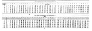
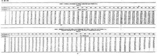
TABLES 1-3 NOAUNALCAPACITIESOFTYPICALTANKS . . . .
TABLES 4-6 MINIMUM CALCULATEDSHELL PLATE THICKNESSFOR
TYPICAL TANKS . . . . . .
PAGE
6
7
7
10
10
16
16
17
17
5:39
39
49
60
63
65
69
69
:i
70
76 *
77
82
88
II-12
12-13
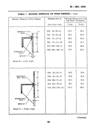
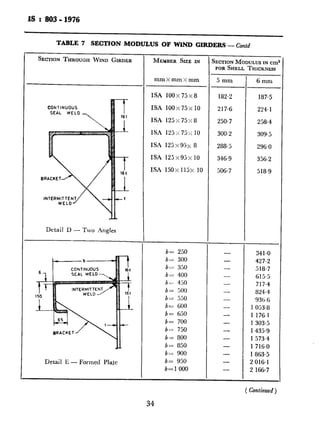
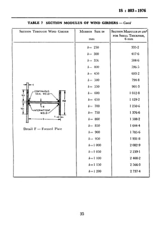
TABLE 7 SECTIONMODULUSOFWIXD GIRDERS . . . . 32-35
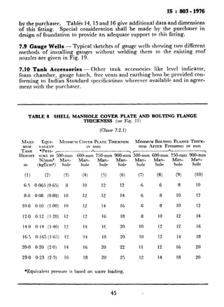
TABLE 8 SHELLMANHOLECOVER PLATEANDBOLTINGFLANGE
THICKNESS . .
4
. . . . . . 45
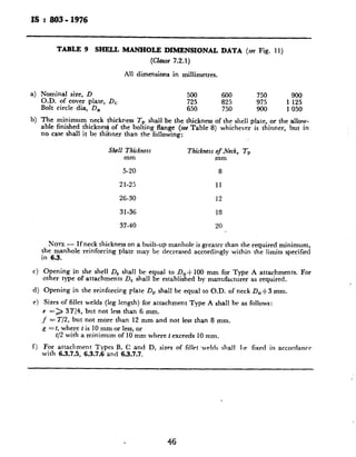
TABLE 9 SHELLMANHOLEDIMENSIONALDATA . . . . 46
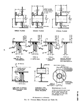
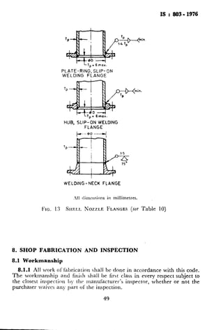
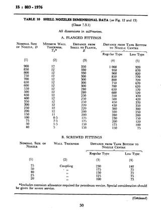
TABLE 10 SHELLNOZZLESDIMEI~SIONALDATA . . . . 50-51
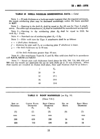
TABLE 11 ROOF MANHOLES * . . . . . 51
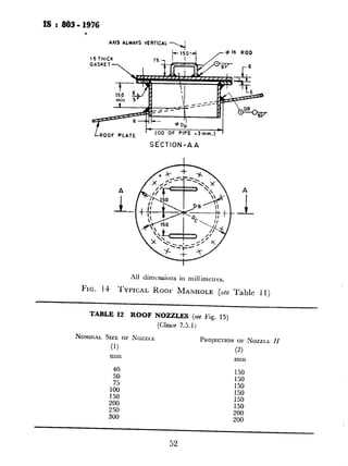
TABLE 12 ROOF NOZZLES . . . . . . 52
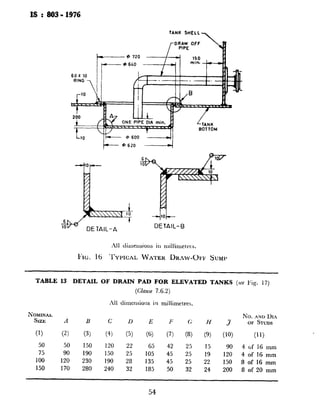
TARLE 13
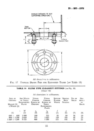
TABLE 14
TABLE I5
TABLE 16
TABLE 17
TABLE 18
TABLE 19
FIGURE 1
~FIGuRE 2
FIGURE 3
FIGURE 4
FIGURE 5
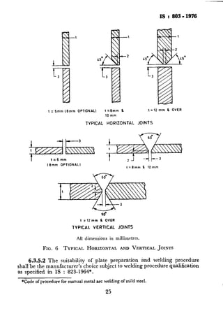
FIGURE 6
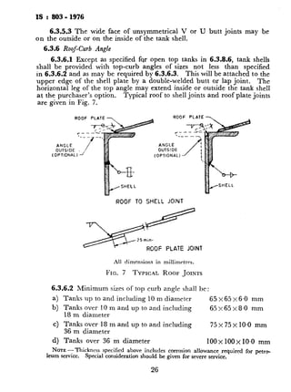
FIGURE 7
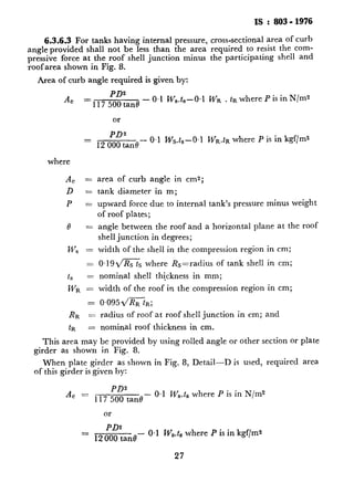
FIGURE 8
FIGURE .9
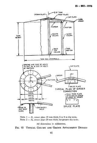
FIGURE 10
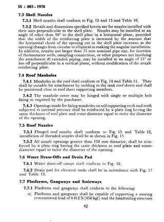
FIGURE 11
FIGURE 12
FIGURE 13
FIGURE 14
FIGURE 15
FIGURE 16
FIGURE 17
FIGURE I8
FIGURE 19
DETAIL OFDRAIN PA
FLUSHTYPE CLEANO
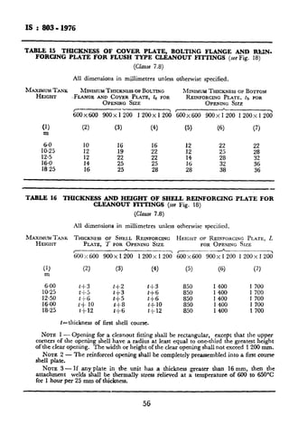
TIIUXNESSOF~COVER
FORCINGPLATEFORI
THICKNESSAND HEIC
FORCLEANOUTFITTII
MAXIMUMPERMISSII~L
GRAPHSPER I50 mm
THERMALVENTINGC
TOTAL RATE OF EME
FIRE EXPOSUREVERS.
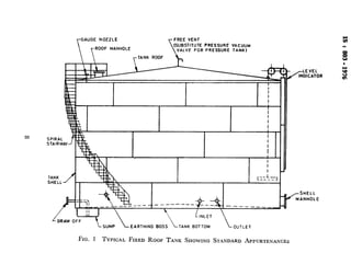
TYPICALFIXEDROOF
TENANCES . .
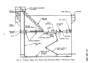
TYPICAL OPEN .To
- SECTIONALVIEW
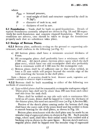
TYPICALFOUNDATION
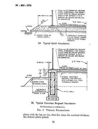
TYPICAL LAYOUT OF’
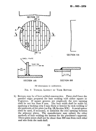
BOTTO~~IPLATEARRA:
TYPICALHORIZONTAI
TYPICALROOFJOINT!
SOUSEPERMISSIBLEDE
RECOMMENDEDLAYO~
TANKS . . . .
TYPICALCOLUMNANT
TYPICAL SHELLMAN:
TYPICALSHELLNozz
SHELLNOZZLE FLANGE
TYPICALROOF MANHC
TYPICALROOF NOZZLE
TYPICALWATER DRAM
TYPICALDRAIN PAD F
TYPICAL FLUSHTYPE
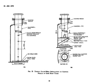
TYPICAL GAUGE-WE]
NOZZLE OF CONE Roo:
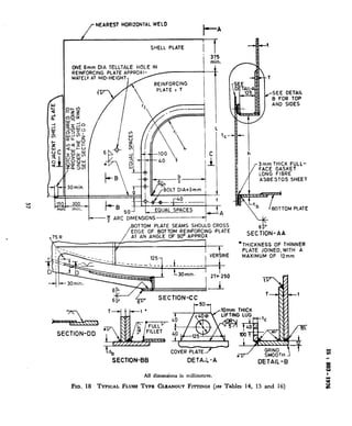
FIGURES20-23 RADIOGRAPHICPORN
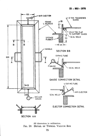
FIGURE24 DETAILOFTYPICALV
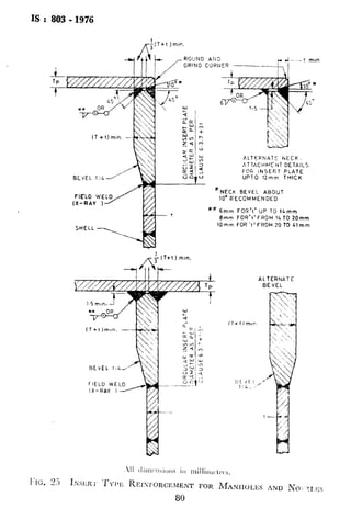
FIGURE25 INSERT TYPE REINFN
NOZZLES . .
4](https://image.slidesharecdn.com/is-160425153502/85/Is-803-1976-8-320.jpg)


![IS : So3 - 1976
(or operator) has welded. If any of such additional spots fails to comply
with the requirements of 11.7, the limits of unacceptable welding shall be
determined as specified for the initial section.
11.9 Repair of Defective Welds - Defects in welds shall be repaired by
chipping or melting OULsuch defects ftom one or from both sides of the
joint, as required, and rewelding. Only sufficient cutting out of defective
joints is required as is necessary to correct the defects,
All repaired welds in joints shall be checked by repeating the original test
procedure.
11.10 Record of Radiographic Examination - A record shall be made
by the erector of.all films, with their identification marks, on a developed
shell plate diagram.
After the completion of the structure, the films shall be the property of
the purchaser, unless otherwise agreed between the purchaser and the
erector.
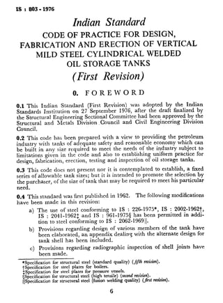
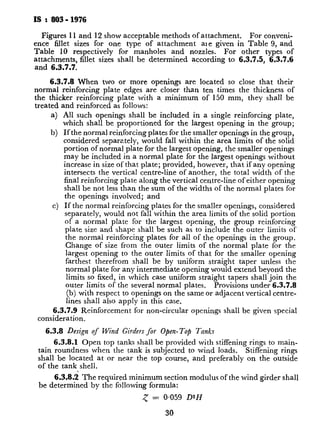
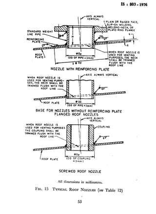
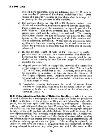
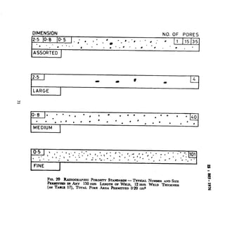
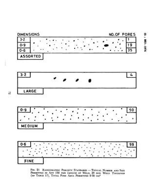
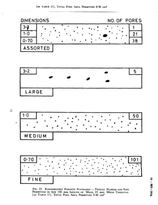
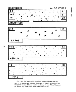
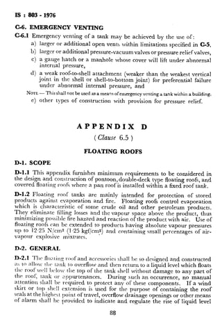
TABLE 17 MAXIMUM PERMISSIBLE POROSITY INDICATIONS IN
RADlOGRAPHS PER 150 mm LENGTH OF WELD (see Fig. ‘20 to 23)
[Ch.se 1$7(d)(5)]
WELD TOTALAREA LARGEPORES MEDIUMPORE FINE PORE
THICKNESS OFPERMITTED
POROSITY ?z- zkzz xz---T l-----J-Number Size Number
(1) (2) (3) (4) (5) (6) .. (7) (8)
cm2 mm mm mm
3 0.05 - - - - 0.40 40
6 0.10 - - 0.6 31 0.40 100
12 0.20 2.5 4, 0.80 40 0.50 101
20 0.30 3.2 4 0,90 50 0.6U 99
25 0.40 3.2 5 I.0 50 0.70 101
40 0.60 3.2 7 1.20 50 0.90 99
50 0.80 3.2 IO 1.4 51 1.0 100
12. TESTING OF TANKS
12.1 Bottom Testing
12.1.1 After the bottom and at least the bottom course of shell plates
have been welded, the bottom shall be tested by pumping air beneath the
bottom plates to a pressure just sufficient to lift them off the foundation
and in any case, not less than 100 mmH,O gauge. The pressure shall be
held by the construction of a temporary dam of clay or other suitable
material around the tank periphery. Soap suds or other suitable material
shall be applied to all joints for detection of leaks.
69](https://image.slidesharecdn.com/is-160425153502/85/Is-803-1976-73-320.jpg)
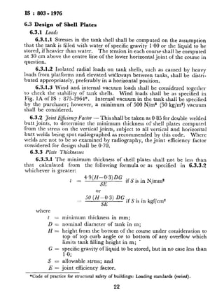
![IS : 803 - I976
B-4. PLATE THICKNESS
B-4.1 The minimum thickness of shell plates shall not be less than that
calculated from the following formula or according to 6.3.3.2 whichever
is greater:
t = 4.9 (H - 0.3) D x G
S
+ c where S is in N/mm2
or
= 5’ (N - y) D ’ G + c where S is in kgf/cms
where
t = minimum thickness in mm;
D = nominal diameter of tank in m;
N = height from the bottom of the course under consideration to
top curb angle or to bottom of any overflow which limits tank
filling height in m;
G = specific gravity of liquid to be stored;
S = allowable stress as computed from B-3.1; and
c = corrosion allowance in mm to be specified by purchaser, but not
less than 1.5 mm.
B-4.2 The manufacturer may use a combination of high strength steel for
lower courses and low strength steel for upper courses, provided that the
thickness of any course is not less than the course immediately above it.
B-5. HYDROSTATIC STRESSES
B-5.1 Stresses in plates due to hydrostatic loading shall not exceed 3/7 of
minimum ultimate tensile stress of the material used. Plate thicknesses
determined by B-4.1 or 6.3.3.2 shall be checked for hydrostatic stresses S,
by the following equation and shall be increased as required to keep it
within specified limits:
s
1
= 4.9 (H - 0.3) D
t
N/mm” < 3/7 Min UTS
or
= 5’ (H t o’3) D kgf/cm2 < 317 Min UTS
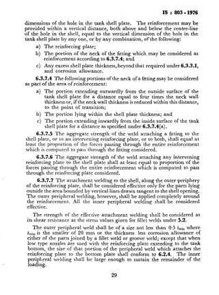
B-6. SHELL CONNECTIONS
B-6.1 All shell opening connections which require reinforcement shall be
attached by welds fully penetrating the shell. Where insert type rein-
forcements, shown in Fig. 25, are used, they shall be butt-welded into the
shell as shown, with the welds having complete penetration and fusion.
78
Welds attaching manholes and nozzles
partial penetration as shown in Fig. 2.
B-6.2 All opening connections 300 mr
welded into a shell plate exceeding 25 mr
-into the shell plate of thickened insert pl:
be stress-relieved before erection. Alto
heat-affected zones on this assembly may
induction heating method, however, prio
the tank. The stress-relieving requireme
bottom annular plate, except for flush t
types cleanout openings, including the bc
plate shall be stress-relieved.
B-6.2.1 Where stress relief has been
periphery weld to a shell butt-weld sha
joints or 75 mm from horizontal joints
spacing is not less than 3 times the shell
apply to the bottom-to-shell joint excep
plate or reinforcing plate may extend tm
joint at approximately 90”.
B-6.3 All welds attaching manholes a
magnetic particle inspection, after stre
hydrostatic test of the tank.
B-6.4 Flush type cleanout openings in ac
with the following exception:
a) The material for shell plate in t
shell reinforcing plate, the tank
neck plate shall conform to ret
b) The maximum height of the 01
900 mm.
c) The upper corner radius rt o
(see Table 14) shall be 600 ml
B-6.5 Piping attached to nozzles on tl
maximum flexibility to eliminate or mini
imposed by, its restraint. Nozzle reinfor
take care of any additional loading caus’
.B-7. RADIOGRAPHY
B-7.1 The following additional radiogra]
in 11 shall be carried out on tanks built I
a) On shell plates up to 10 mm tl
shall be taken on all vertical j
79](https://image.slidesharecdn.com/is-160425153502/85/Is-803-1976-82-320.jpg)
![IS: 803-1976
product, and for tanks with a capacity of less than 500 m3 used for
the storage of crude oil.
f) In the case of viscous oils, such as cutback and penetration grade
asphalts, where the danger of tank collapse resulting from sticking
pallets or from plugging of flame arrestors is greater than the possi-
bility of flame transmission into the tank, open vents may be used
as an exception to the requirement for PV valves or flame-arresting
devices as called for in (c) and (d) above.
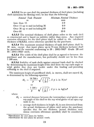
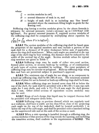
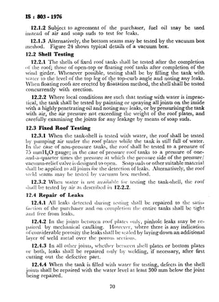
TABLE 18 THERMAL VENTING CAPACITY REQUIREMENTS
(Clauses C-3.3.2 and C-3.4.2)
[Expressed in cubic metres of free air per hour at 10 N/cm% (1 kgf/cms) and 15”C]
TANK CAPACITY VACUUM
(INRI~EATHING)
$3
7.5
;:
120
240
z
600
1 200
1 800
2400
3 000
3 600
4 200
4 800
5 400
6 000
7 200
8 350
9 550
10 750
11 950
(2)
1.75
3
15
z:
18165
145
285
425
570
680
795
880
965
050
::
360
475
590
700
14 300 1 925
16 700 2 125
19 100 2 325
21 500 2 550
PRESSURE(OUTBREATHING)
’ Flash Point
40% or Above
(3)
1.25
1.75
8.5
I7
35
SO
70
187;
255
340
425
485
540
595
655
Flau)r Point
Below 40°C
(4)
1.75
3
:;
60
1;;
285145
425
570
680
795
880
965
1 050
680
765-.
825
880
965
1 020
1 135
1245
1 360
1 475
1 590
1 700
1160 1 925
1275 2 125
1415 2 325
1 53ct 2 550
NOTE- For tanks with intermediate capacities, values may be computed by
interpolation.
TARLE 19 TOTAL RATE OF EMER
EXPOSURE YERSUS
(Clauses C-4.2
‘[Wetted area ZIcrsuscubic metres of free a
WETTED AREA
(1)
m2
2
3
4
5
6
7
8
9
10
12
14
16
18
20
25
30
35
40
50
60
70
80
90
100
120
140
160
180
200
240
280
NOTE -For exposed wetted surface:
C-4-2(b) and G-4.4. For intermediate
ment should be evaluated by interpolat
86](https://image.slidesharecdn.com/is-160425153502/85/Is-803-1976-90-320.jpg)
![IS : 803 - 1976
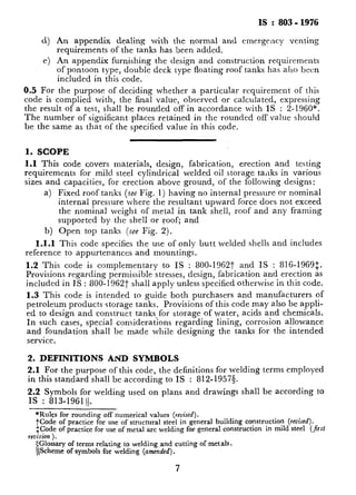
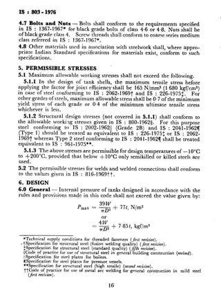
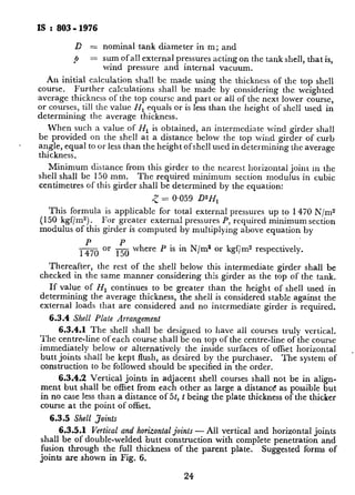
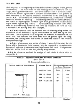
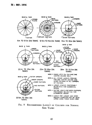
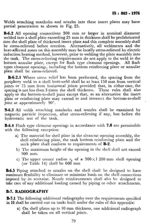
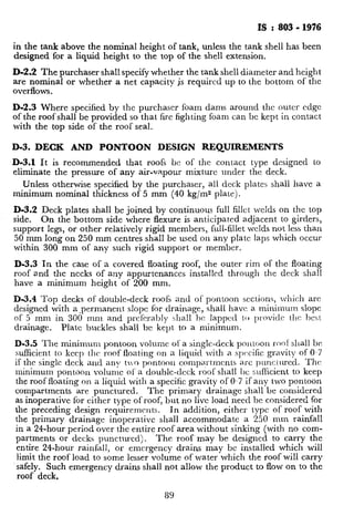
TABLE 19 TOTAL RATE OF EMERGENCY VENTING aEQUIRED FOR FIRE
EXPOSURE VERSUS WETTED SURFACE AREA
(Chses C-4.2, C-4.3 and C-4.5)
.[Wetted area rer$aScubic metres of free air per hour. at 10 N/cm* (1 kgf/cm*) and 15”C]
WETTED AREA
(1)
ma
2
3
4
5
6
7
8
9
10
12
14
16
18
20
25
30
35
40
50
60
70
80
90
100
120
140
160
180
200
240
280
VENTINGREQUIREMENT
(2)
ms/h
600
900
1200
1 500
1 800
2 100
2 400
2 700
3 000
3 600
4 200
4 800
5 400
6 000
6 800
7 500
8 200
8 850
10 000
11 100
12 150
13 100
14 000
14 850
15 800
16656
17 400
18 100
18 750
19 950
21000
NOTE-For exposed wetted surfaces with more than 280 rns area, see C-4.2(a),
C-4-2(b) and C-4.4. For intermediate values of wetted surface area, venting require-
ment should be evalus ted by interpolation.](https://image.slidesharecdn.com/is-160425153502/85/Is-803-1976-91-320.jpg)
![Addenda
arter 4 2;; 3;. clmre
. . . :
6-4.2+5 ) -- Add the foI!oWing
IlfZW clnuse
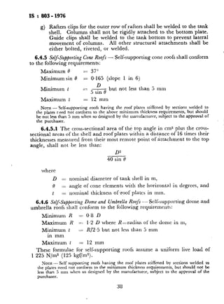
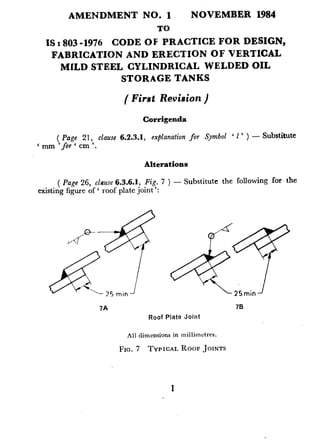
‘ 6.4.2.6 Roof‘ plate shall b , ]-C apped with a minimum overlap of 25
shall be lveldcd vith a continuous fillet weld on the top side only
mm and
shall bc arranged ZIS shown in Fig. (A) or (u) of ITig. 7 for roof pl& k$$
deI)rnding on the IocaI conditions by agreement between the purchaser
and the manufacturer.’
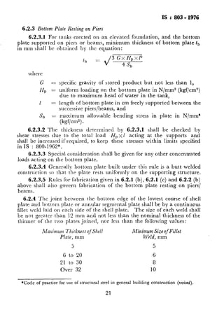
6.2.3 Bottom Plate Resting on Piers
6.2.3.1 FOI- tanks erected on an elevated
plate supported on piers or beams, minimur
in mm shall be obtained by the equation:
m11, =
d__I
4,
( PaRe 36, claw 6.4.2.6 )
as 6.4.2.7.
- Renumber the existing clause 6.4.2.6
G =
HI, =
( SMODC 7)
1 zzz
s, 1
2. *Code of practice for use of structural steel in g
specific gravity of stored PI
uniform loading on the bott
due to maximum head of 7
length of bottom plate in CI
successive piers/beams, and
maximum allowable bend
(kgf/cm2).
6.2.3.2 The thickness determined by
shear stresses due to the total load HP X(
shall be increased if required, to keep these
in IS : 800-1962*.
6.2.3.3 Special consideration shall be g
loads acting on the bottom plate.
6.2.3.4 Generally bottom plate built
construction so that the plate rests uniforr
6.2.3.5 ,Rulcs for fabrication given in I
above shall also govern fabrication of the
beams.
6.2.4 The joint between the bottom CC
plate and bottom plate or annular segmcn
fillet weld laid on each side of the shell pl’
be not greater than 12 mm and not less t:
thinner of the two plates joined, nor less
_Vlaximum Thicktless qf‘Shel1
Plate, mm
5
6 to 20
21 to 30
Over 32
Printed PI Dee Kav Printers. NewDelhi. India 21](https://image.slidesharecdn.com/is-160425153502/85/Is-803-1976-99-320.jpg)