Downloaded 12 times

![A. Dhanaraj Int. Journal of Engineering Research and Applications www.ijera.com
ISSN : 2248-9622, Vol. 5, Issue 4, ( Part -6) April 2015, pp. 32-38
www.ijera.com 35 | P a g e
mt 3
1036.5
1834
3
123
3
123
L
= 1916 mm
III. ANALYSIS OF PRESSURE VESSEL
Structural Results
Table.5: Structural Supports
Name Fixed Support Shell
Material Structural Steel
Mass(kg) 109.69
Volume(m3
) 1.4×10⁻²
Type Fixed Surface
Reaction Force 1.71×10⁻³
N
Reaction Force Vector
[-1.71×10⁻³
Nx, 1.16×10-
7
Ny,
3.67×10⁻⁹
Nz
Reaction Moment 1.81×10⁻⁵
N·m
Reaction moment vector
[1.81×10⁻⁵
N·m x,
3.16×10⁻⁹
N·m y,
1.06×10⁻⁷
N·m z]
Table.6: Structural results
Fig.4: "Equivalent Stress" Contours
Fig.5: "Total Deformation" Contours
Ellipsoidal Dish End
Table.7: Model > Static Structural > Solution >
Results
Object
Name
Equivalent
Stress
Maximu
m Shear
Stress
Total
Deformation
State Solved
Scope
Geometr
y
All Bodies
Definition
Type
Equivalent
(Von-mises)
Stress
Max
Shear
Stress
Total
Deformation
Display
Time
Solved Solved Solved
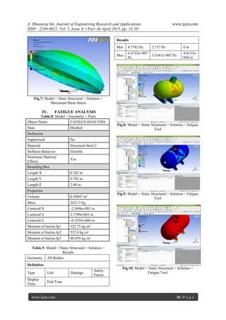
Results
Min
3.101e+006
Pa
1.613e+006
Pa
0 m
Max
3.137e+007
Pa
1.696e+007
Pa
4.1032e-005
m
Fig.6: Model > Static Structural > Solution >
Equivalent Stress
Name Scope Min Max
Equivalent
Stress
Model 8.6×10⁶
Pa 3.5×10⁷
Pa
Maximum
Shear
Stress
Model
4.96×10⁶
Pa
1.87×10⁷
Pa
Total
Deformation
Model 0.0 m
4.27×10⁻⁵
m](https://image.slidesharecdn.com/f504063238-150428014111-conversion-gate02/85/Design-Stress-Analysis-of-a-Cylinder-with-Closed-ends-using-ANSYS-4-320.jpg)

![A. Dhanaraj Int. Journal of Engineering Research and Applications www.ijera.com
ISSN : 2248-9622, Vol. 5, Issue 4, ( Part -6) April 2015, pp. 32-38
www.ijera.com 38 | P a g e
- The design of pressure vessel is initialized with
the specification requirements in terms of
standard technical specifications along with
numerous requirements that lay hidden from the
market.
- The design of a pressure vessel is more of a
selection procedure, selection of its components
to be more precise rather designing each and
every component.
- The pressure vessel components are merely
selected, but the selection is very critical, a slight
change in selection will lead to a different
pressure vessel al- together from what is aimed to
be designed.
- It is observed that all the pressure vessel
components are selected on basis of available
ASME standards and the manufactures also
follow the ASME standards while manufacturing
the components. So that leaves the designer free
from designing the components. This aspect of
Design greatly reduces the Development Time
for a new pressure vessel.
REFERENCES
[1] BHPV manual on Multilayer Pressure
Vessels.
[2] Brownell and Young, "Process Equipment
Design" Chapter 7, Chapter 13, Chapter 14
and Chapter 15. Seely,
[3] F.B., and Smith, A.O., "Advanced Mechanics
of Materials" Wiley, Newyork, Chapter 10.
[4] John F.Henvey “Pressure Vessel Design -
Nuclear and Chemical Applications" An
East-west Edition, Newyork, Chapter 5 and
Chapter 7.
[5] Henry H.Bednar “Pressure Vessel Code
Book", Chapter 11.
[6] Jasper, T.M and Scudder, C.M AIChE
Transactions, PP885 -909.
[7] Fino, A.F., “Economic Considerations for
High Pressure vessel Design" pp-101-104.
[8] Fratcher, G.E: New alloys for Multilayer
Vessels" Vol 33, No.11.
[9] Jasper, T.M and Scudder, C.M “Multilayer
Construction of Thick-wall Pressure
Vessels" Volume 37.
[10] Jawad, Maan H., "Wrapping Stress and Its
Effect on strength of Concentrically Formed
Plywaals," Paper No72-PVP7.](https://image.slidesharecdn.com/f504063238-150428014111-conversion-gate02/85/Design-Stress-Analysis-of-a-Cylinder-with-Closed-ends-using-ANSYS-7-320.jpg)

The document discusses the design and stress analysis of a pressure vessel using ANSYS, focusing on elements such as shell, dish end, and operating manholes based on ASME standards. It highlights the importance of material selection and the implications of pressure loading on vessel integrity, detailing the design process, stress analysis methods for both thin and thick-walled vessels, and emphasizes the significance of adhering to safety standards. Conclusions underscore the necessity for rigorous specification requirements and the importance of component selection over the design of individual parts.