2
Books Recommended
Holland,F. A. Bragg, R. “Fluid flow for Chemical Engineers”,
2nd Edition, Butterworth & Heinemann. 1995.
White, F. M. “Fluid Mechanics”, 4th Edition, McGraw-Hill.
1999.
Noel-de-Nevers “Fluid Mechanics for Chemical Engineers”
McGraw-Hill
McCabe Warren L., Smith Julian C., Harriott peter “Unit
Operations of chemical Engineering” 6thEd. 2001. McGraw-
Hill Inc.
Coulson J. M., Richardson J. F. “Chemical Engineering” Vol-I,
1999. Butterworth, Elsevier.
Fundamentals of Fluid Mechanics, 6th Edition.
3.
3
What We WillStudy
Concept of centrifugal pumps; Centrifugal
pump characteristics; NPSH and its application
in chemical engineering; concept of specific
speed; similarity laws in centrifugal pumps;
pumps in series and parallel; Positive
displacement pumps, their classification,
characteristics and selection; matching system
characteristics with pump characteristics.
Turbo-machinery and its classifications.
4.
4
Compressors, theirclassification,
characteristics and selection. Turbines, their
classification and selection. Compressible flow
and its application in chemical engineering,
concept of choked flow. Flow through porous
media; Fluidization and types of fluidized beds
and their use in chemical engineering, concept
of hydrodynamic characteristics of fluidized
beds. Introduction to non-Newtonian fluids
Concept of various types of valves and their
principles.
5.
Pipe Sizes
Schedule Number
Thewall thickness of a pipe is denoted by schedule number. As the
schedule number increases the thickness of pipe also increases
(10,20,30.....120,160).
Nominal Diameter
It is not inner diameter or outer diameter, It is just a diameter of pipe,
which is near to inner or outer diameter of pipe.
Tube Sizes
The size of tubing is indicated by the outside diameter. Wall
thickness is ordinarily given by the (BWG) Birmingham wire gauge
number, Range 07-24.
At 07 max thickness of tube/sheet.
At 24 min thickness of tube/sheet.
6.
Standard cubic Feetof a Gas
Gas equipment is ordinary rated in terms of standard cubic feet of
gas.
A volume is standard cubic feet, which is measured at specified
temperature and pressure regardless of the actual temperature &
pressure. Various standards are used e.g.
P = 29.92 inch Hg
T= 32 F
St. ft3
of gas = 359 ft3
/lb mole of gas.
P = 30 inch Hg
T= 60 F
St. ft3
of gas = 378.8 ft3
/lb mole of gas.
Gate Valve
Uses ofGate Valve
Stop valve.
Fully open or fully closed.
Not normally consider for throttling purpose.
Suitable for high pressure and high temperature.
Not usually used for slurries and viscous fluids.
Advantages
Low pressure drop.
Provides tight seal when fully closed.
Relatively free of contamination build up.
Disadvantages
Vibration when in partially open.
Seat & disc wears when used for throttling purpose.
Large size gate valves not recommended for steam service.
Required large actuation forces.
11.
11
Typical Usage ofGate Valve
Block valve for control valve
Pump suction valve
Pump discharge valve
Block valve for level controller & level gauge
Drain valve of equipment
Drain valve of process & utility line
First block valve of sampling nozzle
Block valve for safety valve
Block valve for equipment
Block valve for steam trap
By-pass valve for emergency shut-down valve
Flow control valve for large size gas & city water line
12.
GLOBE VALVE
INTRODUCTION
Globevalves are named for their spherical body shape.
The two halves of the valve body are separated by a
baffle with a disc in the center. Globe valves operate by
screw action of the handwheel. They are used for
applications requiring throttling and frequent operation.
Since the baffle restricts flow, they're not recommended
where full, unobstructed flow is required.
14.
Globe Valve
Uses ofGlobe Valve
Flow regulation.
Normally consider for throttling purpose.
Advantages
High pressure drop.
Good shutoff capability
Reasonably good throttling capability
Disadvantages
Costly as compared to gate valves.
Required large actuation forces.
15.
USAGE OF GLOBEVALVE TYPICAL
Manual flow control valve
By-pass valve for control valve
Hose connection
Vent valve of equipment and piping
Minimum flow line for pump
Pressure gauge outlet
By-pass line of reciprocating compressor
16.
Comparison between Gatevalve and Globe Valve
Gate valves are used for On-Off control whereas Globe valves
in addition can also be used for the flow regulation.
Gate valves offer very little resistance to fluid flow in fully open
position and also have small pressure drop across the valve.
Globe valves on the other hand have a high pressure drop
even in fully open conditions and offer substantial resistance to
fluid flow.
Gate valves of the same size are cheaper than globe valves.
Gate valves because of their design have very little fluid
trapping in the line but the globe valves have a larger amount
due to the direction of flow.
Gate valves are unidirectional and can be put around in any
way. The globe valves are not.
17.
VALVE OPERATING DEVICES
Manual
Hand wheel or lever is directly connected to the stem and is
operated by hand
Hydraulic
Hydraulic pressure is applied to one side of a piston which is
connected to the stem of the valve
Motor
A hydraulic, electric, or air driven motor is used to turn the stem of
the valve
Solenoid
Uses an electromagnet to open or close a valve against spring
pressure
18.
SELECTION OF VALVE
Identify application characteristics
Select type of valve required
Select valve size
Select valve end connection
Select valve body, bonnet and trim materials
Identify seat-leakage criteria
Identify requirements for valve-stem packing
arrangement
Be-aware of piping layout and valve orientation
Taken into consideration maintenance requirements
Initial cost
19.
Ball valves
Session 2- Fall 2015 19
• They have a ball-shaped , movable flow control
element in the center of the valve
• They don’t lift the flow control device out of the
process stream. Instead, the hollow ball rotates into
the open or closed position
• Provide very little restriction to flow and can be fully
opened with a quarter turn on the valve handle
• They do not generally seal as well as globe valves
in high pressure service.
• They require a quarter turn on the valve handle to
be totally opened.
Pinch Valves
Uses ofPinch Valves
Systems carrying slurries, gels etc.
Advantages
Low in cost.
Insensitive to contamination.
Have low pressure drop
Tightly closed.
Disadvantages
Flexible membrane in pinch valves are subjected to wear & hence
periodic replacement is required.
Generally limited to low pressure.
Low temperature applications.
Generally required high actuation forces to close off.
23.
Diaphragm Valves
Uses ofDiaphragm Valves
Used for sealing purposes
Suitable for abrasive as well as clean fluids.
Advantages
Offers min resistance to flow in open position.
Due to low pressure drop of diaphragm valve
no stuffing box required.
Any sort of blockage can be cleaned.
Well suited to service where tight, accurate
closure is important.
Diaphragm can be replaced with out removing the body.
Disadvantages
Temperature and pressure are limited.
Limited to pressure of 50 psi.
Application of Diaphragmvalve in Industries
Fertilizer Plants
Water Treatment Plant
Waste Water Treatment Plant
Rayon Plant
Petrochemical Industries
Food Industries
Pharmaceuticals Industries
Sugar Plants
Chemical Industries
Thermal Power Stations
Other Process Industries
26.
Relief valves
• Respondautomatically to sudden increases of
pressure in liquid services
• A disc is held in place by a spring that doesn’t open
until the system pressure exceeds operating limits
• They are designed to open slowly
• For pressurized liquid service and not gases
• The spring tension is adjustable
26
Safety valves
• Respondto excess vapor, or gas, pressures
• The excess pressure is vented to the flare header or
to the atmosphere
• Very similar to a relief valve
• Relief valves are designed to lift slowly
• Safety valves can exhaust more larger flow of gases
at lower velocities
28
Safety Valves
Poppet Valves
Uses
Pressure control.
Check.
Safety.
Relief function.
Advantages
Provides large flow with very little actuator travel.
Excellent leakage control.
Low pressure drop.
Disadvantages
Subject to pressure imbalances which may cause problems in some
applications.
Seating surfaces may be subject to contamination.
32.
Check valves
• Itprevents reverse flow to protect the equipment
from contamination or damaging
• A swing check includes a hinged disc that slams
shut when flow reverse
• Flow keeps the disc open while flowing
32
34
A liftcheck has a disc that rests on the seat when
flow is idle and lift with flow
Lift checks are ideal for systems in which flow rates
fluctuates
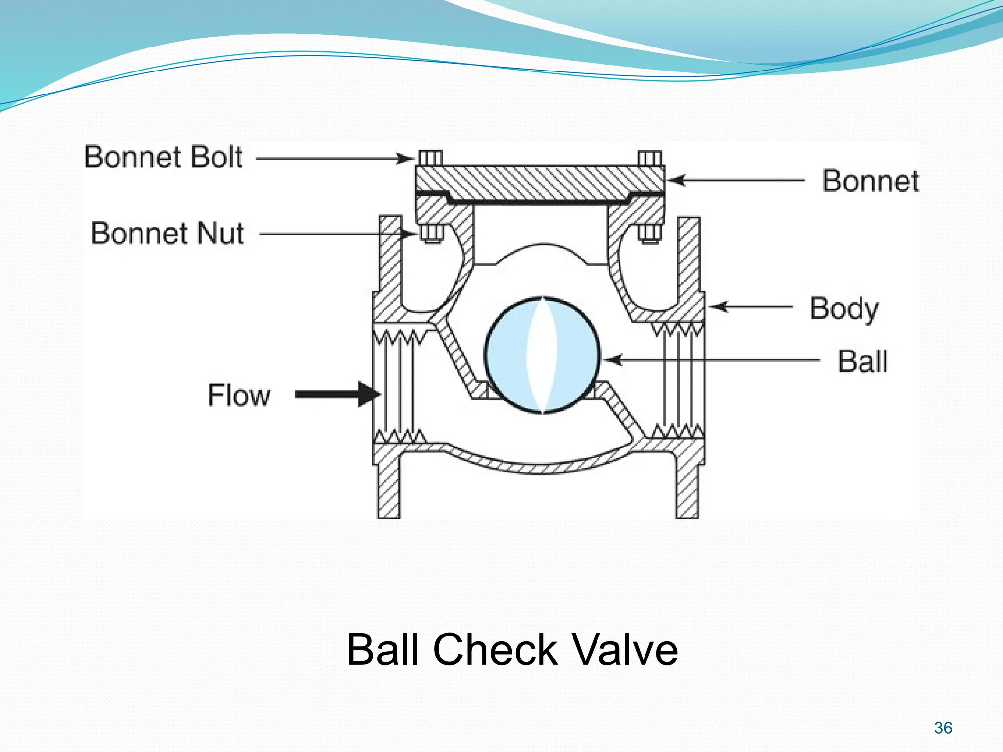
A ball check design, has a ball shaped disc on a
round seat
It is good when flow rates fluctuate or the fluid
contains some solids
The ball and lift checks are more durable than the
swing check
A stopcheck valve has characteristics of a lift check
and a globe valve
In the closed position, the stop check disc is firmly
seated
In the open position, the stem rises out of the body
of the flow control element and acts as a guide for
the disc
The degree of the lift can be controlled
37
38.
Butterfly valves
Arecommonly used for both throttling and on/off
service
Its body is relatively small
The flow control element is a disc
A metal shaft extends through the center of the disc
and allows it to rotate one quarter
Butterfly valves are designed to be operated at low
temperature and low pressure.
38
Plug valves
• Aquick opening, one-quarter turn plug valves are
very popular in the process industry
• The flow control element has a plug shape
• Provide very little restriction to flow
• Can be opened 100% with a one quarter turn on the
valve handle
• Temperatures lower than 480 ºF
41
44
Control valves/Automatic valves
44
•Sensing, indicating, transmitting,
comparing, and/or controlling.
• The final element in a control loop
is a control valve
• Can be air operated, electrically
operated , or hydraulically
operated