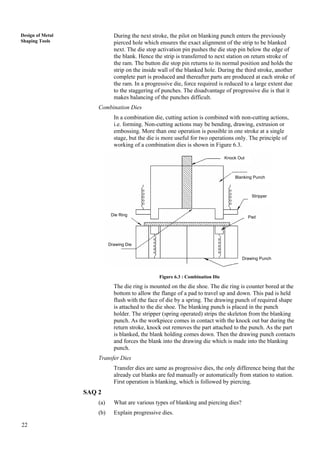
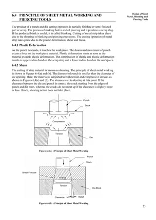
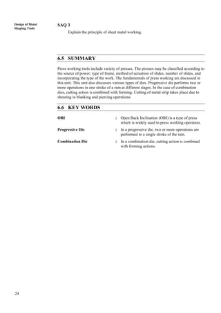
This document discusses sheet metal working tools and presses. It begins by defining sheet metal working as a chip-less manufacturing process for making components under 20mm thick from sheet metal, using a machine called a press. Presses are then classified based on their power source (mechanical or hydraulic), frame type (gap or straight side), number of slides (single, double, triple action), and actuation method (crankshaft, eccentric, etc.). Key press components like the bed, bolster plate, die set, punch, and stripper are also defined. Blanking and piercing dies are introduced, with dies classified by operation type (cutting vs. forming) and method of operation. The objectives are to identify various press
The document discusses power presses, including their types, parts, sizes, tools, and applications. Power presses are metal forming machines that shape or cut metal through mechanical force without removing chips. They are classified based on power source (manually operated vs power driven) and frame design (gap frame, inclinable frame, adjustable bed type, straight side, horn like, pillar). Key parts include the base, frame, ram, pitman, and driving mechanism. Press size is designated by its maximum load capacity. Common press tools are punches, dies, and die sets. Power presses are widely used in industries like automotive, aircraft, and appliance manufacturing.
This document provides information about presses. It begins by defining a press and describing metal forming processes done by presses. It then classifies presses into manual (foot press, arbor press, fly press, toggle press) and power presses (crank press, eccentric press, cam press, screw press, rack & pinion press, hydraulic press, pneumatic press). Several press working terminology are defined, like bed, bolster plate, die set, punch, and stripper. Common press accessories include bases, C-frames, rams, crank shafts, clutches, and brakes. Presses can be selected based on workpiece size, stock width/material, operation type, and required power/speed.
Design of progressive press tool for an alpha meter componenteSAT Journals
Abstract The sheet metal manufacturing Design and development of different components is one of the important phases. like shearing, piercing and blanking etc. There is a highly complex process and leads to various uncertainties. Progressive tool components are modeled in solid works with selected dimensions from the given 2D diagram and design calculations.. Results obtained from theoretical calculations are in good agreement with empirical dimensions of CAD model. Keywords: Die, punch, piercing, CAD.
This document discusses power presses. It provides classifications of presses based on their mechanism, function, structure, and controllability. The main types are mechanical, hydraulic, and pneumatic presses. It also describes the construction and working of gap frame presses, including their components like the flywheel, clutch, brakes, and ram. Cutting operations performed by presses include blanking, piercing, notching, and perforating. Forming operations change the contour through bending and drawing. Safety measures for presses include bi-manual controls and light sensors.
PROJECT REPORTCOMMON BENDING TOOL DESIGN FOR TWO SHEET METAL COMPONENTS (LEF...Rohit kumar vidyarthi
The document discusses different types of press tools used in sheet metal forming operations. It describes common tools like blanking tools, piercing tools, bending tools, forming tools, and compound tools. Compound tools can perform multiple operations simultaneously, like blanking and piercing, to produce parts in a single stroke. The document provides details about the components of compound tools and examples of various press operations including blanking, piercing, cutting off, parting off, trimming, and shaving. It explains progressive, compound and combination tool configurations.
Type Of Non cutting Operations (Press Tool)Veer Singh
This document provides information about press tools and presses. It discusses metal forming processes that use presses and press tools to deform metal workpieces into desired shapes through the application of pressure. It then describes the major components of a press working system and various criteria for classifying presses, including by power source, frame type, number of actions, drive mechanism, intended operations, and other specifications. It provides examples of different types of presses and explains specifications that define a press, such as maximum force, stroke length, die space, and shut height.
1. The document describes the design and analysis of a punching die. It aims to design an interchangeable die and punches to reduce weight by changing materials.
2. The die set is designed to perform individual operations at each station with a single press stroke, unlike a progressive die. The parts are designed in SolidWorks and analyzed using SimulationXpress.
3. The die, punches, and guide pins are made of LM6 alloy for its light weight and hardness. The bottom plate is designed to provide space for die operations while withstanding bending stresses well below its limits.
Metal hydroforming uses pressurized fluid to deform metals into shaped dies. Key equipment includes hydraulic forming presses, hydroform water systems, pressure intensifiers, and hydroforming tools. Presses are available in various sizes and pressures, and include features like short cycle times and large tables. Pressure intensifiers help increase internal pressure to levels needed for proper deformation. Routine maintenance and teleservice systems can help reduce costs and downtime.
The document discusses punching and blanking processes, which are sheet metal forming processes where a finite volume of metal is removed from a sheet using a die and punch. Key details include:
- Punching and blanking are used widely in automotive, aerospace, and appliance industries for mass production.
- The cutting tools are usually hardened steel or tungsten carbide, while the sheet metal can be materials like aluminum, brass, copper, and stainless steel.
- In punching, the final product is the sheet with material removed, while in blanking it is the removed portion. Punching presses provide the force needed and can be manually or CNC controlled.
This seminar discusses the design and manufacturing of bearing cups. It describes the different types of presses and dies used in the process, including blanking, piercing, and drawing dies. Calculations are shown for determining the required forces for each operation. The total force required for the compound die is estimated to be 8.4 tons. The cost of manufacturing the die is estimated to be Rs. 9000. The seminar concludes that bearing cups can be efficiently manufactured in batches of 6000 using this compound die.
This document provides an overview of presses and press classification. It begins with introductions and definitions of press working terminology. Presses are then classified in several ways: by power source (manual, power); frame type (inclinable, gap, straight side); number of actions (single, double, triple); purpose of use (shearing, punching, etc.); and position of frame (inclinable, vertical, horizontal). Common types of presses are also described briefly, including fly, gap frame, hydraulic, and screw presses. The document is from a seminar on press classification presented by Sanket Chandankhede of the Mechanical Engineering department at Yeshwantrao Chavan College of Engineering, Nagpur
This document provides an overview of designing stamping dies, specifically blanking dies. It discusses:
1. The basic components and structure of standard blanking dies, including the upper and lower die sets, punch, stripper, and die holder.
2. The design flow for blanking dies, including blanking layout, stripper design, punch design, and assembly of the die sets.
3. Key considerations for individual die components like providing sufficient clearance and distances between parts, and designing punches, strippers, and die holders to simplify fabrication and assembly while withstanding forces during stamping.
The document describes a project report on the design of a common bending tool for two sheet metal components (left and right). It discusses the history of metal shaping tools and introduces press tools and their types like blanking, piercing, bending, etc. It also covers topics like strip layout, types of strip layout arrangements, factors that affect strip arrangement, die design parameters and calculations. The key objectives are to maximize material utilization, reduce production costs, and increase part output through an efficient strip layout and tool design.
1. The document discusses sheet metal forming processes including shearing, bending, and springback. It provides definitions and formulas for calculating forces in shearing and springback in bending.
2. An lab experiment is described that involves bending aluminum strips using a finger brake machine and measuring the resulting bend radii and angles to analyze springback.
3. Finite element analysis simulations are shown illustrating the deformation during bending and springback.
Manufacturing Technology , Bending Process .
Tackles mainly about the definition of Bending process, how does it work, the machines & equipment used to make it work and the application of Bending on manufacturing Industries.
Please Don't forget to Like before you download the presentation.
Press working is a manufacturing process that uses presses to form sheet metal components. It involves both cutting and non-cutting operations. Common cutting operations include blanking, punching, trimming, and notching. Common non-cutting operations include bending, drawing, and squeezing. A press machine consists of a bed, bolster plate, die set with lower and upper shoes, punches, and other components. The travel of the punch during penetration progresses through three zones: compression, shearing, and breakage. Clearance is applied between the punch and die depending on whether the operation is punching or blanking. Different types of die sets are used depending on the shape and complexity of the part being formed.
The document discusses three types of bending that occur when sheet metal is bent: partial bending, bottoming, and coining. It explains the relationship between bending force and bending angle through an S-curve diagram. Partial bending and bottoming occur through air bending with relatively low force, while coining requires much higher force and eliminates springback for greater precision. Springback occurs due to the material retaining elasticity even after yielding. The document also discusses bottoming as the most common air bending technique, providing a table relating sheet thickness to optimal V-width for the die.
This lecture defines important terms of the process of stretch forming and it describes the basic processes of stretch forming. Background in production engineering and familiarity with the subject matter covered in TALAT This lecture 3701 is assumed.
This document provides information on bending theory and design principles for bending operations. It discusses the following key points in 3 sentences:
Types of bending covered include V-bending, edge bending, and flanging. Springback occurs as the bent part partially recovers its original shape after bending forces are removed. The document outlines methods to compensate for springback like overbending and bottoming, and provides formulas to estimate springback and calculate bending allowance and force.
Sheet metal bending involves straining flat sheet perpendicular to its length to form a bend. During bending, fibers on the outside of the bend are stretched while fibers on the inside are compressed. At some point within the material lies the neutral bending line where forces cancel out. Common bending operations include V-bending using a V-shaped die, edge bending which clamps and wipes material into a die, and U-bending into channels. Proper consideration of bend allowance, springback, and bending force is required to achieve the desired bend geometry. Other bending operations are flanging, hemming, curling, seaming, and staking.
The document is a report on the fabrication of a c-clamp submitted by engineering students at Cairo University. It describes the objective of making the c-clamp to learn manufacturing processes. It then details the processes used, including cutting the raw material to size, drilling a hole, and welding a nut. Dimensions of the finished part are provided. Photos show the different steps of rasping, drilling, and welding. Various welding processes are also defined.
This document discusses the design of progressive and compound dies for metal stamping. It begins by explaining how a progressive four-up die can be used to meet production requirements of 1,000,000 washers per week. It describes layouts for multiple parts per stroke, including the use of angled strip layout. It also discusses elements like finger stops, automatic stops, pilots, and punch plates that are used in progressive die design. Finally, it provides an overview of compound and combination dies, which perform multiple operations in a single stroke.
this file is about the types of dies and also its manufacturing procedure.this is important for the industry and for the industrial and manufacturing engineering..are of this field is manufacturing engineering and die designalso for the blanking dies and punches
The document provides an overview of metal cutting principles and processes. It discusses:
- The fundamentals of metal cutting including chip formation and common cutting processes like turning, milling, and cutting-off.
- Key variables that influence the cutting process like cutting speed, feed, depth of cut, tool material, and workpiece material.
- Different tool geometries including single-point and multi-point tools as well as tool nomenclature systems.
- The mechanics of chip formation involving shear deformation along the shear plane as material is removed.
- The two main methods of metal cutting - orthogonal and oblique cutting.
Guide to Centerless External Cylindrical Grinding – part II of the reference ...Machine Tool Systems Inc.
Guide to Centerless External Cylindrical Grinding – part II of the reference work:
Thanks in particular to its high productivity, centerless external cylindrical grinding established itself some time ago as a successful grinding procedure. The most important interrelations in centerless grinding are explained in the Guideline for Centerless External Cylindrical Grinding. In the second part you will find out more about the grinding gap and plunge grinding.
Basics of Tube Bending explores the fundamentals of bending with a mandrel, bending tube with a plug mandrel, a ball mandrel and wiper die, and also explores and troubleshoots some of the most common tube bending problems and issues!
This document discusses machine tools and machining processes. It covers topics such as cutting tools, tool selection factors, tool design and terminology, forces in metal cutting, tool life, cutting speeds and feeds, tool failure modes, machinability, cutting inserts, and cutting fluids. The document is presented by Vikrant Sharma of the Mechanical Engineering department and contains diagrams to illustrate machining concepts.
This document provides an overview of grinding machines and grinding processes. It begins by defining grinding as a machining process that removes material using an abrasive wheel. It then describes various types of grinding machines including cylindrical grinders, surface grinders, tool and cutter grinders, form grinders, thread grinders, gear grinders, centreless grinders, and some recently developed grinding machines. The document also discusses different grinding operations like rough grinding, precision grinding, external cylindrical grinding, internal cylindrical grinding, surface grinding, and form grinding.
Mechanical Technology Grade 12 Chapter 6 Terminology Of MachinesFuture Managers
This slide show accompanies the learner guide "Mechanical Technology Grade 10" by Charles Goodwin, Andre Lategan & Daniel Meyer, published by Future Managers Pty Ltd. For more information visit our website www.futuremanagers.net
This document provides information about lathe machines, including their construction, types, and specifications. It discusses the main components of lathes like the bed, headstock, tailstock, and carriage. It describes different types of lathes such as speed lathes, engine lathes, bench lathes, tool room lathes, capstan and turret lathes, and automatic lathes. It also covers topics like lathe operations, taper turning methods, thread cutting, and lathe attachments. Specification factors for lathes like height of centers, swing diameter, length between centers are defined.
Sheet metal can be bent into various shapes by applying forces that strain the material around a straight axis. There are two main types of bending: V-bending using a V-shaped die, and edge bending using a wiping die. When bending, the material below the neutral axis is compressed and above is stretched. The amount of stretching depends on the bend radius and thickness, and can be estimated using a bend allowance formula. After bending, springback may occur as the material elasticity causes the bend angle to increase toward its original shape. The maximum required bending force can be calculated based on the material properties, part dimensions, and die type.
Assessment & Optimization of Influence of Some Process Parameters on Sheet Me...IRJET Journal
This document discusses optimization of sheet metal blanking process parameters through experimental studies and modeling. The study aims to assess how sheet thickness, clearance, wear radius, and shear angle influence burr height, accuracy, and circularity in blanking medium carbon steel. Experiments were conducted using an orthogonal array to evaluate these parameters. Response tables and graphs identified optimal levels for blanking. Taguchi's Grey Relational Analysis was found to be an effective technique for parameter optimization in blanking. The document provides background on blanking process mechanics and definitions various die and press components.
sheet metal work ,die and punch.
it is generally useful for sheet metal operation.terminology of die and punch, types of die,types of punch,cutting force,method of reducing cutting force
This document provides information on sawing and broaching machines. It begins with an introduction and then discusses the classification, components, operation, and applications of sawing machines such as reciprocating saws, band saws, and circular saws. It also covers broaching, including the construction and operation of broaching machines as well as different types of broaches and their applications in machining processes. The document aims to explain the basic concepts and components of sawing and broaching machines.
This document is an internship report for Pakistan Ordnance Factories (POF) that describes visits to various weapon manufacturing shops. It discusses the processes and machinery used to manufacture weapon parts and assemble final weapons like pistols, rifles, and machine guns. The report focuses on the press and welding, barrel, and machine shops. It provides details on the various machines like lathes, mills, and presses used to cut, shape, and join metal parts into completed weapons.
Machine tools are power-driven devices used to produce parts by removing material from preformed blanks through cutting tools. The document discusses lathes, which are machine tools that remove metal from a workpiece to achieve a desired size and shape. It describes the main components of an engine lathe, including the bed, headstock, tailstock, carriage, feed mechanism, and thread cutting mechanism. It also discusses other types of lathes, lathe accessories, and specifications used to describe lathe characteristics.
This document provides an overview of milling machines and milling processes. It describes the two main types of milling machines - horizontal and vertical milling machines. It outlines common cutting tools and industrial applications of milling. The key milling processes of spindle speed, feed rate, depth of cut, and cutter rotation direction are explained. Typical milling operations such as plain milling, end milling and gang milling are defined. The document also covers workholding methods and the importance of vice alignment and safety practices.
1) A band saw machine uses a continuous metal band blade to cut metal workpieces. The blade is supported and driven by a drive wheel and idler wheel.
2) There are two main types - vertical band saws, which are more common, and horizontal band saws, which are used for simple cuts of solid materials held in a vice.
3) Key operations include ripping (cutting lengthwise), cross-cutting (cutting across the grain), mitering (cutting at an angle), re-sawing (cutting thickness), and freehand cutting (without guides for curves and angles). Band saws can cut a variety of materials and shapes.
The document provides information about shaper machines. It begins with an introduction describing shapers as reciprocating machine tools used to produce flat surfaces. It then discusses the history of shapers, invented in 1836. The main body describes the various types of shapers classified by ram motion and table design. It also explains the key components of a shaper like the base, column, ram, and tool head. In closing, it covers the Whitworth quick return mechanism used in shapers and automatic feed mechanisms.
The document discusses hydraulic presses made by Anhui Lai Fu NC Machine Tool Co. Ltd. Specifically, it describes their YL32 series four-column hydraulic presses. The presses have a three-beam, four-pole structure for stability and space for large dies. They can be operated manually or semi-automatically. The presses offer accuracy, rigidity, stability, flexible controls, safety features, and the ability to precisely control stroke and pressure. Deep drawing is also discussed, which uses hydraulic presses or double-action presses to form sheet metal parts through drawing and stamping.
Sheet metal forming operations involve bending and shaping thin metal sheets. Common forming processes include shearing, punching, blanking, and bending. Characteristics of the sheet metal like grain size, residual stresses, and springback affect formability. Proper tool and die design can control these characteristics and improve forming quality and accuracy. Forming methods range from simple stamping to advanced techniques like hydroforming, electrohydraulic forming, rubber pad forming, and superplastic forming of specialized alloys.
The document provides information about various metalworking machines including shaper machines, slotting machines, and planer machines. It describes the basic workings of each machine, including their main components and functions. Shaper machines cut flat or irregular surfaces using a reciprocating ram and tool head. Slotting machines are similar but cut slots and keyways using a vertically reciprocating ram. Planer machines cut flat surfaces by moving the workpiece under a stationary cutting head as it moves back and forth on ways.
The document discusses various types of lathe machines and their components and operations. It begins with an introduction to lathes, describing them as important metalworking tools that rotate the workpiece while a cutting tool shapes it. It then explains different lathe types like engine lathes, speed lathes, and CNC lathes. The main lathe components discussed are the bed, headstock, tailstock, carriage, and lead screw. Common lathe operations like turning, threading, boring, drilling and tapering are also summarized.
Milling is a machining process that uses a rotating multi-toothed cutter to remove material from a workpiece. Milling machines can hold one or more cutters and precisely rotate and index workpieces to cut flat, curved, and threaded surfaces to close tolerances. Milling machines are classified based on their design and include column and knee mills, manufacturing mills, and planer mills. The principal parts of a column and knee mill include the base, column, knee, saddle, overarm, spindle, arbor, and various milling cutters. Milling cutters come in different shapes like plain, side, angle, and end mills to perform operations like slotting and profiling.
The document provides an overview of the main parts and functions of a center lathe. It details the key components like the headstock, chuck, spindle, carriage, saddle, and tailstock. It explains the main tasks that can be performed on a lathe, including facing, turning, drilling, boring, and thread cutting. The document emphasizes the importance of understanding how to correctly and safely operate a lathe as its fast moving parts and cutting tools can cause serious injuries if mishandled.
i hope, it will helpful to the students and peoples in the search of topics mentioned
it is informative to study to even get passing marks or for revision
The document provides an overview and instructions for operating and maintaining an SH series cone crusher. It describes the crusher's structure, performance specifications including capacity and technical parameters, working principles, installation requirements, and procedures for installing key components like the frame, drive shaft, pulley, and eccentric sleeve. The document is intended to help users correctly operate and maintain the crusher to achieve optimal performance and productivity.
Software Engineering and Project Management - Introduction, Modeling Concepts...Prakhyath Rai
Introduction, Modeling Concepts and Class Modeling: What is Object orientation? What is OO development? OO Themes; Evidence for usefulness of OO development; OO modeling history. Modeling
as Design technique: Modeling, abstraction, The Three models. Class Modeling: Object and Class Concept, Link and associations concepts, Generalization and Inheritance, A sample class model, Navigation of class models, and UML diagrams
Building the Analysis Models: Requirement Analysis, Analysis Model Approaches, Data modeling Concepts, Object Oriented Analysis, Scenario-Based Modeling, Flow-Oriented Modeling, class Based Modeling, Creating a Behavioral Model.
Electric vehicle and photovoltaic advanced roles in enhancing the financial p...IJECEIAES
Climate change's impact on the planet forced the United Nations and governments to promote green energies and electric transportation. The deployments of photovoltaic (PV) and electric vehicle (EV) systems gained stronger momentum due to their numerous advantages over fossil fuel types. The advantages go beyond sustainability to reach financial support and stability. The work in this paper introduces the hybrid system between PV and EV to support industrial and commercial plants. This paper covers the theoretical framework of the proposed hybrid system including the required equation to complete the cost analysis when PV and EV are present. In addition, the proposed design diagram which sets the priorities and requirements of the system is presented. The proposed approach allows setup to advance their power stability, especially during power outages. The presented information supports researchers and plant owners to complete the necessary analysis while promoting the deployment of clean energy. The result of a case study that represents a dairy milk farmer supports the theoretical works and highlights its advanced benefits to existing plants. The short return on investment of the proposed approach supports the paper's novelty approach for the sustainable electrical system. In addition, the proposed system allows for an isolated power setup without the need for a transmission line which enhances the safety of the electrical network
Discover the latest insights on Data Driven Maintenance with our comprehensive webinar presentation. Learn about traditional maintenance challenges, the right approach to utilizing data, and the benefits of adopting a Data Driven Maintenance strategy. Explore real-world examples, industry best practices, and innovative solutions like FMECA and the D3M model. This presentation, led by expert Jules Oudmans, is essential for asset owners looking to optimize their maintenance processes and leverage digital technologies for improved efficiency and performance. Download now to stay ahead in the evolving maintenance landscape.
Embedded machine learning-based road conditions and driving behavior monitoringIJECEIAES
Car accident rates have increased in recent years, resulting in losses in human lives, properties, and other financial costs. An embedded machine learning-based system is developed to address this critical issue. The system can monitor road conditions, detect driving patterns, and identify aggressive driving behaviors. The system is based on neural networks trained on a comprehensive dataset of driving events, driving styles, and road conditions. The system effectively detects potential risks and helps mitigate the frequency and impact of accidents. The primary goal is to ensure the safety of drivers and vehicles. Collecting data involved gathering information on three key road events: normal street and normal drive, speed bumps, circular yellow speed bumps, and three aggressive driving actions: sudden start, sudden stop, and sudden entry. The gathered data is processed and analyzed using a machine learning system designed for limited power and memory devices. The developed system resulted in 91.9% accuracy, 93.6% precision, and 92% recall. The achieved inference time on an Arduino Nano 33 BLE Sense with a 32-bit CPU running at 64 MHz is 34 ms and requires 2.6 kB peak RAM and 139.9 kB program flash memory, making it suitable for resource-constrained embedded systems.
Use PyCharm for remote debugging of WSL on a Windo cf5c162d672e4e58b4dde5d797...shadow0702a
This document serves as a comprehensive step-by-step guide on how to effectively use PyCharm for remote debugging of the Windows Subsystem for Linux (WSL) on a local Windows machine. It meticulously outlines several critical steps in the process, starting with the crucial task of enabling permissions, followed by the installation and configuration of WSL.
The guide then proceeds to explain how to set up the SSH service within the WSL environment, an integral part of the process. Alongside this, it also provides detailed instructions on how to modify the inbound rules of the Windows firewall to facilitate the process, ensuring that there are no connectivity issues that could potentially hinder the debugging process.
The document further emphasizes on the importance of checking the connection between the Windows and WSL environments, providing instructions on how to ensure that the connection is optimal and ready for remote debugging.
It also offers an in-depth guide on how to configure the WSL interpreter and files within the PyCharm environment. This is essential for ensuring that the debugging process is set up correctly and that the program can be run effectively within the WSL terminal.
Additionally, the document provides guidance on how to set up breakpoints for debugging, a fundamental aspect of the debugging process which allows the developer to stop the execution of their code at certain points and inspect their program at those stages.
Finally, the document concludes by providing a link to a reference blog. This blog offers additional information and guidance on configuring the remote Python interpreter in PyCharm, providing the reader with a well-rounded understanding of the process.
Rainfall intensity duration frequency curve statistical analysis and modeling...bijceesjournal
Using data from 41 years in Patna’ India’ the study’s goal is to analyze the trends of how often it rains on a weekly, seasonal, and annual basis (1981−2020). First, utilizing the intensity-duration-frequency (IDF) curve and the relationship by statistically analyzing rainfall’ the historical rainfall data set for Patna’ India’ during a 41 year period (1981−2020), was evaluated for its quality. Changes in the hydrologic cycle as a result of increased greenhouse gas emissions are expected to induce variations in the intensity, length, and frequency of precipitation events. One strategy to lessen vulnerability is to quantify probable changes and adapt to them. Techniques such as log-normal, normal, and Gumbel are used (EV-I). Distributions were created with durations of 1, 2, 3, 6, and 24 h and return times of 2, 5, 10, 25, and 100 years. There were also mathematical correlations discovered between rainfall and recurrence interval.
Findings: Based on findings, the Gumbel approach produced the highest intensity values, whereas the other approaches produced values that were close to each other. The data indicates that 461.9 mm of rain fell during the monsoon season’s 301st week. However, it was found that the 29th week had the greatest average rainfall, 92.6 mm. With 952.6 mm on average, the monsoon season saw the highest rainfall. Calculations revealed that the yearly rainfall averaged 1171.1 mm. Using Weibull’s method, the study was subsequently expanded to examine rainfall distribution at different recurrence intervals of 2, 5, 10, and 25 years. Rainfall and recurrence interval mathematical correlations were also developed. Further regression analysis revealed that short wave irrigation, wind direction, wind speed, pressure, relative humidity, and temperature all had a substantial influence on rainfall.
Originality and value: The results of the rainfall IDF curves can provide useful information to policymakers in making appropriate decisions in managing and minimizing floods in the study area.
Optimizing Gradle Builds - Gradle DPE Tour Berlin 2024Sinan KOZAK
Sinan from the Delivery Hero mobile infrastructure engineering team shares a deep dive into performance acceleration with Gradle build cache optimizations. Sinan shares their journey into solving complex build-cache problems that affect Gradle builds. By understanding the challenges and solutions found in our journey, we aim to demonstrate the possibilities for faster builds. The case study reveals how overlapping outputs and cache misconfigurations led to significant increases in build times, especially as the project scaled up with numerous modules using Paparazzi tests. The journey from diagnosing to defeating cache issues offers invaluable lessons on maintaining cache integrity without sacrificing functionality.
Introduction- e - waste – definition - sources of e-waste– hazardous substances in e-waste - effects of e-waste on environment and human health- need for e-waste management– e-waste handling rules - waste minimization techniques for managing e-waste – recycling of e-waste - disposal treatment methods of e- waste – mechanism of extraction of precious metal from leaching solution-global Scenario of E-waste – E-waste in India- case studies.
1. 17
Design of Sheet
Metal, Blanking and
Piercing Tools
UNIT 6 DESIGN OF SHEET METAL,
BLANKING AND PIERCING TOOLS
Structure
6.1 Introduction
Objectives
6.2 Description of Press Working Tools
6.2.1 Source of Power
6.2.2 Type of Frames
6.2.3 Fundamentals of Press Operation
6.2.4 Press Working Terminology
6.3 Types and Applications of Blanking and Piercing Die
6.4 Principle of Sheet Metal Working and Piercing Tools
6.4.1 Plastic Deformation
6.4.2 Shear
6.5 Summary
6.6 Key Words
6.1 INTRODUCTION
Sheet metal working may be defined as a chip-less manufacturing process by which
various components are made from sheet metal. The thickness of sheet is generally less
than 20 mm. The machine used for sheet metal working is called press. The main features
of a press are: A frame which supports the ram or slide, a bed, a source of mechanism for
operating the ram in line with and normal to the bed. The ram is equipped with suitable
punch and die block is attached to the bed. The sheet metal working components are
produced by downward motion of punch and towards the die block. The punch and die
block assembly is called die set. These operations are usually done at room temperature.
Objectives
After studying this unit, you should be able to
• identifying various press working tools,
• know various piercing and blanking operation, and
• understand the principle of sheet metal working.
6.2 DESCRIPTION OF PRESS WORKING TOOLS
Press working tools include variety of press. The press may be classified according to
source of power; type of frame; method of actuation of slides; and the number of slides
incorporating the type of the work.
6.2.1 Source of Power
The presses are classified according to the source of power used. The two main source of
power for applying force to the ram or slide of a press are mechanical and hydraulic.
The linear movement of the ram is obtained with the help of a flywheel driven system in
mechanically operated press. The heavy flywheel absorbs energy from the motor
continuously and delivers its stored energy to the workpiece when required. The
flywheel is attached to the main shaft of the press (non-geared) or it is attached to the
main shaft with the help of gear train. For short stroke and low tonnage, non-geared
drives are useful. Number of strokes per minute is usually quite high for non-gear drives.
2. 18
Design of Metal
Shaping Tools
Gear train may contain single or double reduction gear. The single reduction gear is
suited for heavier blanking operations or shallow blanking. Double reduction gear is used
for high tonnage, but with less number of strokes per minute. These are faster than
hydraulic presses and require less maintenance and capital cost. Hydraulic presses consist
of large cylinder and piston arrangement coupled to a hydraulic pump. The piston and
press ram form one unit. The ram can be operated by oil press on the piston in the
cylinder. The capacity of hydraulic press depends upon the cross section area of the
piston and pressure developed by the pump. The hydraulic press can exert full pressure at
any position of the ram stroke. The speed and pressure is constant throughout the entire
stroke. It is easy to operate.
6.2.2 Type of Frames
The presses are classified according to the type of frames such as gap frame and straight
side frame.
Presses with Gap Frame
Presses with gap frame are produced with solid frames in a vertical or inclined
position. They are cut back in the form of letter “C” below the ram so that strip is
fed from the side. Some presses have open-back so that strip is fed from front to
back. A press is inclined so that the parts may fall through the open-back by
gravity. Now-a-days, open-back inclination (OBI) is widely used for blanking and
piercing operations on small workpieces.
Presses with Straight Side Frame
Presses with straight side frame consist of a slide or ram which travels up and
down between two straight slides or housings. They are extensively used for large
and heavy work. The size of a press is limited due to the presence of housings. It
has longer strokes due to the frame construction. These presses are further
classified as single point, two point and four point suspensions, depending upon
the number of connections between the slide and the main drive shaft.
According to the Number of Slides
There are three presses according to the number of slides, viz. single-action
presses, double-action presses and triple-action presses.
A single-action press has one slide, whereas a double-action press has two
slides, viz. one inner and the other outer slide. It is generally used for
drawing operation in which outer slide carries the blank holder and inner
slide carries the punch. Outer slide has shorter stroke than inner. Two slides
move in the same direction and against the fixed bed of the press.
The working of a triple-action press is same as the double-action press with
the addition of third ram. Three rams are located in the press bed. It moves
upwards immediately after other two ram moves down. All three actions are
properly synchronized for drawing, redrawing and forming.
According to the Method of Actuation (Slide)
These presses consist of flywheel attached to the main shaft. The rotary
motion of flywheel is converted into the linear motion of the slide or ram.
This is achieved by using crankpins or eccentrics into the main drive shaft.
The number of points of suspension of the slide determines the number of
throws or eccentric on the main shaft. The points of suspensions are places
where pressure is transmitted by connection to the slide. The shut height of
the press can be varied with the help of adjustable connecting rods or
pitmans. The main advantage of eccentric is that it offers more surface area
for bearing the support for pitman. The limitation of eccentric is that the
length of stroke is limited. Crankshaft driven device provides longer strokes.
3. 19
Design of Sheet
Metal, Blanking and
Piercing Tools
The slides are also actuated by cams, toggle, rack and pinions, screws and
knuckles.
6.2.3 Fundamentals of Press Operation
The force by which press ram is able to exert safely is called tonnage of the press. Press
slides exert a force which is greater than the rated tonnage because of built-in safety
factor. The tonnage of hydraulic press is equal to the product of the piston area and oil
pressure in cylinder. The tonnage is varied by changing the oil pressure. Tonnage of
mechanical press is equal to the size of bearings for the crankshaft or eccentric. The
tonnage of mechanical press is approximately equal to the product of shear stress of
crank shaft material and area of crankshaft bearings. The tonnage of mechanical press is
maximum when the slide is near to the bottom of its stroke.
Stroke
Reciprocating motion of a press slide is called the stroke. Stroke is expressed as
the number of inches between terminal points of the motion. The stroke is constant
for mechanical press while it is adjustable for hydraulic press.
Shut Height
The distance from the top of the bed to the bottom of the slide with the stroke
down and the adjustment up is called shut height.
Die Space
Die space is the area available for mounting dies in the press.
6.2.4 Press Working Terminology
A simple cutting die is shown in Figure 6.1.
Shank
Ram
Back Up Plate
Guide Post
Bushing
Punch Holder
Punch Plate
Punch
Guide Post
Die Block
Die Holder
Bolster Plate
Bed
Figure 6.1 : Simple Cutting Die
Bed
The bed is lower part of press frame that serves as a table on which a bolster plate
is mounted.
Bolster Plate
Bolster plate is a thick plate secured to the press bed, which is used for locating
and supporting the die assembly. Its thickness is usually 5 to 12.5 cm.
Die Set
4. 20
Design of Metal
Shaping Tools
Die set is unit assembly which incorporates a lower and upper shoe, two or more
guide posts and guide post bushings.
Die
Die is the female part of a complete tool for producing work in a press. It is also
referred to a complete tool consisting of pair of mating members for producing
work in press.
Die Block
It is the block or a plate which contains the die cavity.
Lower Shoe
The lower shoe of a die set is generally mounted on the upper plate of a press. The
die block is mounted on the lower shoe. The guide posts are also mounted in it.
Punch
Punch is the male component of the die assembly which is directly or indirectly
moved by or fastened to the press ram or slide.
Upper Shoe
It is the upper part of the die set which contain die post bushings.
Punch Plate
The punch plate or punch retainer fits closely over the body of the punch and holds
it in proper relative position.
Back Up Plate
It is also called pressure plate. It is placed so that the intensity of pressure does not
become excessive on punch holder. The plate distributes the pressure over a wide
area and intensity of pressure on the punch holder is reduced to avoid crushing.
Stripper
Stripper is a plate which is used to strip the metal strip from a cutting or
non-cutting punch or die. It may also guide the strip.
Knock Out
Knock out mechanism is used to remove the workpiece from a die. It is connected
to and operated by the press ram.
Pitman
Pitman is a connecting rod which is used to transmit the motion from the main
drive shaft to the press slide.
SAQ 1
(a) Discuss various types of press working tools differentiated according to
source of power.
(b) What are the different types of press working tools according to type of
frame?
5. 21
Design of Sheet
Metal, Blanking and
Piercing Tools
6.3 TYPES AND APPLICATIONS OF BLANKING AND
PIERCING DIE
Types of Die
Dies are classified according to the type of press operation and according to the
method of operation.
According to the type of the press operation, dies are classified as cutting dies and
forming dies.
Cutting Dies
Cutting dies are used to cut the metal. They use cutting and shearing action
for cutting the metal. Examples of cutting dies are blanking dies, piercing
dies, perforating dies, notching dies, trimming dies, shaving dies and
nibbling dies, etc.
Forming Dies
Forming dies change the shape of the blank without removing any stock.
Example of forming dies are drawing dies, bending dies and squeezing dies.
According to the method of operation, dies are classified as simple dies,
compound dies, combination dies, progressive dies, transfer dies and steel
rule dies, etc.
Progressive Die
It is also called a follow on die. The progressive die is shown in Figure 6.2.
It performs two or more operations in one stroke of a ram at different stages.
First operation is punching, which is followed by blanking. The metal strip
is transferred to the next station in between the stroke to produce a complete
workpiece.
Station 1
A
Station 2
A
9
8
7
6
5
(1) Metal Strip
(2) Die stop activating pin
(3) Primary die stop
(4) Blanking punch
(5) Piercing punch
(6) Punch plate
(7) Stripper
(8) Die block
(9) Die set
(10) Automatic button stop
(11) Punch pilot
42
1
10
11
Figure 6.2 : Progressive Die
When the piercing punch cuts a hole in the strip, the blanking punch draws
out a portion of the metal strip in which a hole had been pierced at a
previous station. The metal strip is fed into the die mechanically or
manually. The primary stop is pushed in by hand and lead end is then made
to contact with it. The press is now made to operate to pierce a hole at
station 1. As the primary stop is released, the strip is transferred to the
station 2. The strip contacts with automatic button die stop at station 2.
6. 22
During the next stroke, the pilot on blanking punch enters the previously
pierced hole which ensures the exact alignment of the strip to be blanked
next. The die stop activation pin pushes the die stop pin below the edge of
the blank. Hence the strip is transferred to next station on return stroke of
the ram. The button die stop pin returns to its normal position and holds the
strip on the inside wall of the blanked hole. During the third stroke, another
complete part is produced and thereafter parts are produced at each stroke of
the ram. In a progressive die, force required is reduced to a large extent due
to the staggering of punches. The disadvantage of progressive die is that it
makes balancing of the punches difficult.
Design of Metal
Shaping Tools
Combination Dies
In a combination die, cutting action is combined with non-cutting actions,
i.e. forming. Non-cutting actions may be bending, drawing, extrusion or
embossing. More than one operation is possible in one stroke at a single
stage, but the die is more useful for two operations only. The principle of
working of a combination dies is shown in Figure 6.3.
Knock Out
Blanking Punch
Stripper
Die Ring
Pad
Drawing Die
Drawing Punch
Figure 6.3 : Combination Die
The die ring is mounted on the die shoe. The die ring is counter bored at the
bottom to allow the flange of a pad to travel up and down. This pad is held
flush with the face of die by a spring. The drawing punch of required shape
is attached to the die shoe. The blanking punch is placed in the punch
holder. The stripper (spring operated) strips the skeleton from the blanking
punch. As the workpiece comes in contact with the knock out bar during the
return stroke, knock out removes the part attached to the punch. As the part
is blanked, the blank holding comes down. Then the drawing punch contacts
and forces the blank into the drawing die which is made into the blanking
punch.
Transfer Dies
Transfer dies are same as progressive dies, the only difference being that the
already cut blanks are fed manually or automatically from station to station.
First operation is blanking, which is followed by piercing.
SAQ 2
(a) What are various types of blanking and piercing dies?
(b) Explain progressive dies.
7. 23
Design of Sheet
Metal, Blanking and
Piercing Tools
6.4 PRINCIPLE OF SHEET METAL WORKING AND
PIERCING TOOLS
The product of a punch and die cutting operation is partially finished or semi-finished
part or scrap. The process of making hole is called piercing and it produces a scrap slug.
If the produced blank is useful, it is called blanking. Cutting of metal strip takes place
due to the shearing in blanking and piercing operations. The cutting operation of metal
strip takes place due to the plastic deformation, shear and break.
6.4.1 Plastic Deformation
As the punch descends, it touches the workpiece. The downward movement of punch
exerts a force on the workpiece material. Plastic deformation starts as soon as the
material exceeds elastic deformation. The combination of elastic and plastic deformation
results in upper radius band on the scrap strip and a lower radius band on the workpiece.
6.4.2 Shear
The cutting of strip material is known as shearing. The principle of sheet metal working
is shown in Figures 6.4(a) and (b). The diameter of punch is smaller than the diameter of
die opening. Here, the material is subjected to both tensile and compressive stresses as
shown in Figures 6.4(a) and (b). The stresses start to develop at this point. If the
clearance between the die and punch is correct, the crack starting from the edges of
punch and die meet, whereas the cracks do not meet up if the clearance is slightly more
or less. Hence, shearing action does not take place.
Punch
Stock
Compression
Tension
Die
Figure 6.4(a) : Principle of Sheet Metal Working
Punch
Stock
Shear Fracture
Tension
Die Block
ReliefClearance
Figure 6.4(b) : Principle of Sheet Metal Working
8. 24
Design of Metal
Shaping Tools
SAQ 3
Explain the principle of sheet metal working.
6.5 SUMMARY
Press working tools include variety of presses. The presses may be classified according to
the source of power; type of frame, method of actuation of slides, number of slides, and
incorporating the type of the work. The fundamentals of press working are discussed in
this unit. This unit also discusses various types of dies. Progressive die performs two or
more operations in one stroke of a ram at different stages. In the case of combination
dies, cutting action is combined with forming. Cutting of metal strip takes place due to
shearing in blanking and piercing operations.
6.6 KEY WORDS
OBI : Open Back Inclination (OBI) is a type of press
which is widely used in press working operation.
Progressive Die : In a progressive die, two or more operations are
performed in a single stroke of the ram.
Combination Die : In a combination die, cutting action is combined
with forming actions.