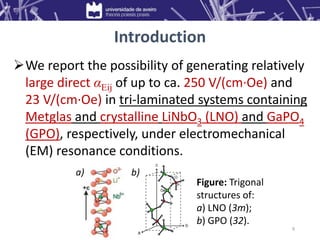
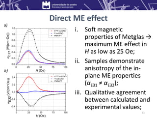
This document summarizes research on tri-layered magnetoelectric composites containing Metglas and various piezoelectric crystals. Key findings include:
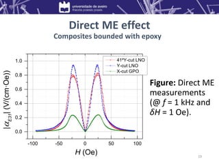
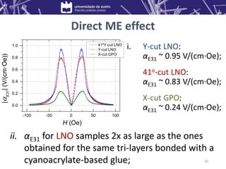
1) Composites of Metglas/lithium niobate (LNO) and Metglas/gallium phosphate (GPO) exhibited direct magnetoelectric voltage coefficients of up to 0.95 V/(cm·Oe) and 0.24 V/(cm·Oe), respectively.
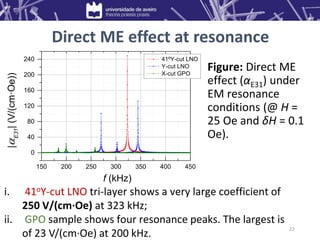
2) Under electromechanical resonance, the Metglas/LNO composite showed a very large coefficient of 250 V/(cm·Oe), while the Metglas/GPO composite showed a maximum of 23 V/(

![Introduction
• DC and AC magnetic field sensors;
• Electric current sensors;
• Multiple-state memories;
• RAM memories;
• Transformers;
• Read-heads;
• Diodes;
• Spin wave generators;
• Electrically tunable
microwave devices.
Applications
• Single-phase (multiferroics) • Composites
ME materials
• Intrinsic ME effect;
• Too small for any
practical application;
• Only at very low
temperatures.
• Incorporate both
ferroelectric (FE) and
ferri/ferromagnetic
(FM) compounds;
• Can exhibit large ME
effects at RT.
[W. Eerenstein et al.,
Nature 442 (2006)]
3](https://image.slidesharecdn.com/presentation-vacuum-220814040227-03df4060/85/Presentation-Vacuum-pptx-3-320.jpg)
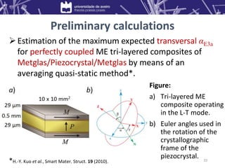
![Preliminary calculations
(deg)
(deg)
LiNbO3 Maximum |E| (V/cm-Oe)
0 20 40 60 80 100 120 140 160 180
0
20
40
60
80
100
120
140
160
180
5
10
15
20
25
(deg)
(deg)
GaPO4 Maximum |E| (V/cm-Oe)
0 20 40 60 80 100 120 140 160 180
0
20
40
60
80
100
120
140
160
180
5
10
15
20
25
30
35
Piezoelectric
crystal
Maximum
|𝛼𝐸3𝑎|
(V/(cm·Oe))
Crystal cut
LNO 27.2 (ZXl) 39o
α–GPO 35.6 (XYt) 12o
PMN–31%PT
([011]-poled)
23.2 Z
Conclusion: Selection of
crystals with an appropriate
cut → very important step in
the development of good
ME composites.
Table: maximum expected
direct ME voltage coefficients.
LNO
GPO
11](https://image.slidesharecdn.com/presentation-vacuum-220814040227-03df4060/85/Presentation-Vacuum-pptx-11-320.jpg)
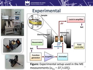
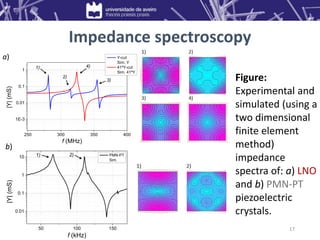
![ Metglas/Piezocrystal/Metglas tri-layered composites
prepared:
Piezocrystals: Y-, 41oY-cut LNO and [011]-poled PMN-PT;
Bounding method: Cyanoacrylate-based glue;
Piezocrystals: Y-, 41oY-cut LNO and X-cut GPO;
Bounding method: Epoxy resin.
ME properties studied:
• Impedance spectroscopy performed using a simple I-V
equivalent circuit;
• Direct ME effects measured by a dynamic lock-in technique
using a home-made setup.
Experimental
12](https://image.slidesharecdn.com/presentation-vacuum-220814040227-03df4060/85/Presentation-Vacuum-pptx-12-320.jpg)
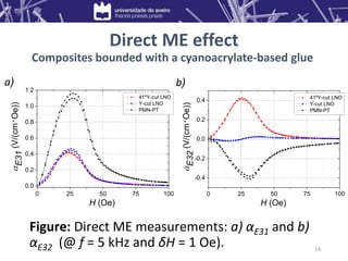
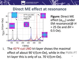
![23
Composite
Crystal
dimensions
(mm3)
Quasi-static
|αE3a|
(V/(cm·Oe))
EM resonance
|αE3a|
(V/(cm·Oe))
Ref.
M / 41oY-cut LNO / M 10 x 10 x 0.5 0.8 @ 25 Oe 250 @ 323 kHz -
M / X-cut GPO / M 10 x 10 x 0.5 0.2 @ 25 Oe 23 @ 200 kHz -
M / [011]-poled PMN-PT / M 10 x 10 x 0.5 1.2 @ 27 Oe 70 @ 150 kHz -
P / X-cut Quartz / P 45 x 5 x 0.5 4.8 @ 30 Oe 175 @ 58 kHz [1]
P / X-cut LGT / P 25 x 4.5 x 0.4 6.3 @ 40 Oe 155 @ 80 kHz [2]
P / PZT / P 25 x 4.5 x 0.4 0.6 @ 90 Oe 110 @ 90 kHz [2]
P / [001]-poled PMN-PT / P 20 x 5 x 0.3 1.3 @ 180 Oe 70 @ 115 kHz [2]
Direct ME effect
Table: Summary of the ME properties in some tri-layered composites.
FM alloys: Metglas (M); Permendur (P).
[1] G. Sreenivasulu et al., Phys. Rev. B 86(21), 214405 (2012);
[2] G. Sreenivasulu et al., Appl. Phys. Lett. 100(5), 052901 (2012).](https://image.slidesharecdn.com/presentation-vacuum-220814040227-03df4060/85/Presentation-Vacuum-pptx-23-320.jpg)