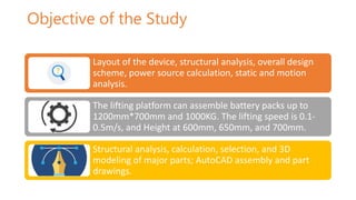
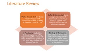
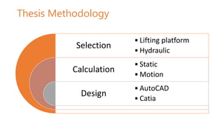
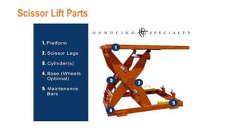
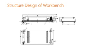
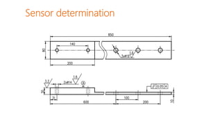
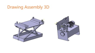
Prepared By: IBNA KAWSAR
Supervised By: Professor ZhiguoAn (安治国)
Mechanical Engineering and Automation
Chongqing Jiaotong University
Structure design of lifting table for
power lithium-ion battery pack.
Objective of the Study
Layout of the device, structural analysis, overall design
scheme, power source calculation, static and motion
analysis.
The lifting platform can assemble battery packs up to
1200mm*700mm and 1000KG. The lifting speed is 0.1-
0.5m/s, and Height at 600mm, 650mm, and 700mm.
Structural analysis, calculation, selection, and 3D
modeling of major parts; AutoCAD assembly and part
drawings.
Literature Review
Utama Panwar, et al the design
of hydraulic scissor lift
components that lift up 300kg
of load with a raise of 3.5ft.
Gaffer G Momin, et al found
design and analysis of
mechanical, pneumatic, or
hydraulic type lift more
compact and suitable for
medium scale work.
N. Pandit, et al studied the
design, analysis, and safety
requirements of the scissor lift.
Safety of the worker operating it
and gives the guidelines for
handling the unit
Sandeep G. Thorat, et al
(2013) Scissor lift can lift a
load up to 4000 kg up to the
height of 7ft. The lift is easy
to use and daily maintenance
is not required,
Thesis Methodology
Selection
Calculation
Design
• Lifting platform
• Hydraulic
• Static
• Motion
• AutoCAD
• Catia
Scissor Lift Parts
Force Analysis of lifting workbench
F1 = F3 = 3950
Overall stress diagram.
F5 = 0
F6 = F7 = 3750
Shear force MN Stress Diagram.
Shear Force and Bending Moment
Diagram
Shear diagram of shear force MN. Shear force MN bending moment
diagram.
Stress analysis of shear force
Shear force AB stress diagram.
Shear Force and Bending Moment
Diagram
Shear diagram of shear force AB.
Shear force AB bending moment
diagram.
Structure Design of Workbench
Sensor determination
Calculation of hydraulic system
• The Hydraulic scissor lift mechanism relies
on cylinders filled with a reservoir of
hydraulic fluid
• The flow of hydraulic fluid is controlled by
valves and causes the cylinder to push
outwards or retract inwards, with a
corresponding motion from the scissor legs
• Relatively easy to operate, hydraulic scissor
lifts are suitable for a range of applications at
different scales.
Internal Force
Hydraulic pump and Motor Selection
YBD-50
Y132M2-6
Model
Hydraulic fuel tank
Drawing Assembly 2D
Drawing Assembly 3D
Thank you

DefensePresentation.pptx

  • 1.
    Prepared By: IBNAKAWSAR Supervised By: Professor ZhiguoAn (安治国) Mechanical Engineering and Automation Chongqing Jiaotong University Structure design of lifting table for power lithium-ion battery pack.
  • 2.
    Objective of theStudy Layout of the device, structural analysis, overall design scheme, power source calculation, static and motion analysis. The lifting platform can assemble battery packs up to 1200mm*700mm and 1000KG. The lifting speed is 0.1- 0.5m/s, and Height at 600mm, 650mm, and 700mm. Structural analysis, calculation, selection, and 3D modeling of major parts; AutoCAD assembly and part drawings.
  • 3.
    Literature Review Utama Panwar,et al the design of hydraulic scissor lift components that lift up 300kg of load with a raise of 3.5ft. Gaffer G Momin, et al found design and analysis of mechanical, pneumatic, or hydraulic type lift more compact and suitable for medium scale work. N. Pandit, et al studied the design, analysis, and safety requirements of the scissor lift. Safety of the worker operating it and gives the guidelines for handling the unit Sandeep G. Thorat, et al (2013) Scissor lift can lift a load up to 4000 kg up to the height of 7ft. The lift is easy to use and daily maintenance is not required,
  • 4.
    Thesis Methodology Selection Calculation Design • Liftingplatform • Hydraulic • Static • Motion • AutoCAD • Catia
  • 5.
  • 6.
    Force Analysis oflifting workbench F1 = F3 = 3950 Overall stress diagram.
  • 7.
    F5 = 0 F6= F7 = 3750 Shear force MN Stress Diagram.
  • 8.
    Shear Force andBending Moment Diagram Shear diagram of shear force MN. Shear force MN bending moment diagram.
  • 9.
    Stress analysis ofshear force Shear force AB stress diagram.
  • 10.
    Shear Force andBending Moment Diagram Shear diagram of shear force AB. Shear force AB bending moment diagram.
  • 11.
  • 12.
  • 13.
    Calculation of hydraulicsystem • The Hydraulic scissor lift mechanism relies on cylinders filled with a reservoir of hydraulic fluid • The flow of hydraulic fluid is controlled by valves and causes the cylinder to push outwards or retract inwards, with a corresponding motion from the scissor legs • Relatively easy to operate, hydraulic scissor lifts are suitable for a range of applications at different scales. Internal Force
  • 14.
    Hydraulic pump andMotor Selection YBD-50 Y132M2-6 Model
  • 15.
  • 16.
  • 17.
  • 18.