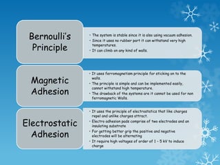
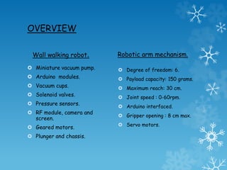
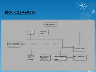
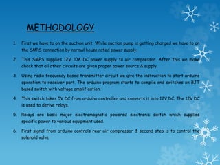
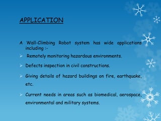
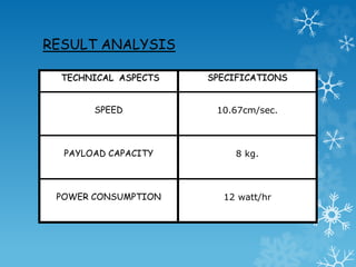
Wall walking robot with robotic arm .
(controlled via RF Module)
Guided by :- Mrs. G. Vimalarani
Assistant Professor(SG),EIE
Team Members :-
Aditya Sharan Gupta 1000708005
Anuraj Kumar 1000708017
Nayan Jyoti Medhi 1000708060
Shrayam Srivastava 1000708099
ABSTRACT
The concept is to design and develop multifunctional wall walking
robot for application of good flexibility and stability. Main idea
is to attain a specialized wall walking robot where it can be
applied in the applications like monitoring purposes, as a spy bot
for military use, working in hazardous environment, etc. As by
idea, the bot has been designed simpler in order to meet
required positions like it has to give lift to self-i.e., bot body and
payload. The necessary instruments and parts are arranged
specifically to keep the waste made on interpretation of weight,
size, power usage, calibration, etc. The bot is controlled via RF
module through Arduino Uno controller. This controller executes
program based on C programing. The Arduino receives the RF
frequency and run the program. Through program the necessary
parts are driven and bot is made to move. Everything is
standardized to meet the necessity of project. We aim single
control of bot movement & arm movement.
OBJECTIVE
The objective of this work is to attain a specialized work in wall
walking robot where it can be applied in application:-
 Monitoring purposes.
 As a spy bot for military use.
 Working in hazardous environment.
We also wish to use it for further research and extend most
of its capabilities.
BACKGROUND
The wall climbing project done previously has
encountered number of unnecessary
customaries which basically require heavy and
traditional electronics and mechanical design
that decreased it’s usability to certain
extents.
Disadvantages:-
• Cost of project.
• Heavy vacuum generator.
• Low area of working.
• Straight path can only be followed.
• The system is stable since it is also using vacuum adhesion.
• Since it uses no rubber part it can withstand very high
temperatures.
• It can climb on any kind of walls.
Bernoulli’s
Principle
• It uses ferromagnetism principle for sticking on to the
walls.
• The principle is simple and can be implemented easily,
cannot withstand high temperature.
• The drawback of the systems are it cannot be used for non
ferromagnetic Walls.
Magnetic
Adhesion
• It uses the principle of electrostatics that like charges
repel and unlike charges attract.
• Electro adhesion pads comprise of two electrodes and an
insulating substrate
• For getting better grip the positive and negative
electrodes will be alternating
• It require high voltages of order of 1 – 5 kV to induce
charge
Electrostatic
Adhesion
OVERVIEW
Wall walking robot.
 Miniature vacuum pump.
 Arduino modules.
 Vacuum cups.
 Solenoid valves.
 Pressure sensors.
 RF module, camera and
screen.
 Geared motors.
 Plunger and chassis.
Robotic arm mechanism.
 Degree of freedom: 6.
 Payload capacity: 150 grams.
 Maximum reach: 30 cm.
 Joint speed : 0-60rpm.
 Arduino interfaced.
 Gripper opening : 8 cm max.
 Servo motors.
ADVANTAGES OF PROPOSED SYSTEM
 Area of working being increased distinctly.
 No use of huge and heavy components in project.
 Cost of production being decreased at very higher level.
 Easy to accommodate and transport.
 RF modeling helped to use wirelessly.
BlOCK DIAGRAM
METHODOLOGY
1. First we have to on the suction unit. While suction pump is getting charged we have to on
the SMPS connection by normal house rated power supply.
2. This SMPS supplies 12V 10A DC power supply to air compressor. After this we make
check that all other circuits are given proper power source & supply.
3. Using radio frequency based transmitter circuit we give the instruction to start arduino
operation to receiver part. The arduino program starts to compile and switches on BJT
based switch with voltage amplification.
4. This switch takes 5V DC from arduino controller and converts it into 12V DC. The 12V DC
is used to derive relays.
5. Relays are basic major electromagnetic powered electronic switch which supplies
specific power to various equipment used.
6. First signal from arduino controls rear air compressor & second step is to control the
solenoid valve.
7. The third air compressor mechanism is controlled in this step.
Solenoid valve is an electromagnetic valve used to control the
direction of negative air pressure.
8. Three air pressure gauges are attached for simplicity having 2
as +ve pressure gauge and one as –ve pressure gauge.
9. The circuit is functioning properly is checked by three LED
arrangements.
APPLICATION
A Wall-Climbing Robot system has wide applications
including :-
 Remotely monitoring hazardous environments.
 Defects inspection in civil constructions.
 Giving details of hazard buildings on fire, earthquake,
etc.
 Current needs in areas such as biomedical, aerospace,
environmental and military systems.
PROBLEM FACED & RECTIFIED
1. Firstly the major deal was to think of design without
traditional large equipment which was made possible by keen
search of team members.
2. All the older models made previously were too complex, idea
of keeping it linked to basic principles helped us to achieve
simplicity.
3. The use of DC geared motor& rack-pinion design was applied
first to achieve movement, later it was made possible using
pneumatic cylinders.
4. Suction generation was major part above all cost and
availability of mini suction units was problem which got
rectified by NBM suction machine.
RESULT ANALYSIS
TECHNICAL ASPECTS SPECIFICATIONS
SPEED 10.67cm/sec.
PAYLOAD CAPACITY 8 kg.
POWER CONSUMPTION 12 watt/hr
TABULAR ANALYSIS
0
2
4
6
8
10
12
14
16
18
PROPOSED
SYSTEM
PREVIOUS
SYSTEM
The mechanical design of the robot includes the design of load
handling of each cup. The robot needs to carry a load of 8 kg, so the
cups are designed accordingly. The movement of the system is
carried out by a driving air compressor which will take care of the
movement. The movement is controlled by an arduino controller which
will take care of algorithmic handling of the robot. The adhesion
system of the robot is vacuum suction system our case we use
chambered vacuum cup so that the air flow can be controlled and the
load handling capacity could be enhanced. The negative pressure is
generated by a vacuum generator placed outside the robot the air
will be carried through the tube which will enhance more redundancy
then even if the robot fall it can be taken back. Along with the tube
there will be control wire that will run to the arduino controller from
the pc for data transfer which will give enhanced security. The
enhancements that need to be implemented in system are the
integration of camera system and sensor network for the detection
of cracks of the wall.
CONCLUSION
References
 In-house project by Hindustan University student Er. Prabhakaran under
guidance of University faculty Mr. G. Muthukumaran (Associate Professor,
EIE).
 Keen observation and guidance by Mrs. G. Vimalarani (Assistant
Professor(SG), EIE).
 Related works by other researchers and students under this title .
 TaeWon Seo, Member, IEEE, and Metin Sitti, Senior Member, Ieee/Asme
Transactions On Mechatronics, Vol. 18, 1 February 2013.
 XiaoQi Chen, Senior Member, IEEE, Matthias Wager, Mostafa Nayyerloo,
Wenhui Wang, Member, IEEE, and J. Geoffrey Chase 2007

Wall Walking Bot

  • 1.
    Wall walking robotwith robotic arm . (controlled via RF Module) Guided by :- Mrs. G. Vimalarani Assistant Professor(SG),EIE Team Members :- Aditya Sharan Gupta 1000708005 Anuraj Kumar 1000708017 Nayan Jyoti Medhi 1000708060 Shrayam Srivastava 1000708099
  • 2.
    ABSTRACT The concept isto design and develop multifunctional wall walking robot for application of good flexibility and stability. Main idea is to attain a specialized wall walking robot where it can be applied in the applications like monitoring purposes, as a spy bot for military use, working in hazardous environment, etc. As by idea, the bot has been designed simpler in order to meet required positions like it has to give lift to self-i.e., bot body and payload. The necessary instruments and parts are arranged specifically to keep the waste made on interpretation of weight, size, power usage, calibration, etc. The bot is controlled via RF module through Arduino Uno controller. This controller executes program based on C programing. The Arduino receives the RF frequency and run the program. Through program the necessary parts are driven and bot is made to move. Everything is standardized to meet the necessity of project. We aim single control of bot movement & arm movement.
  • 3.
    OBJECTIVE The objective ofthis work is to attain a specialized work in wall walking robot where it can be applied in application:-  Monitoring purposes.  As a spy bot for military use.  Working in hazardous environment. We also wish to use it for further research and extend most of its capabilities.
  • 4.
    BACKGROUND The wall climbingproject done previously has encountered number of unnecessary customaries which basically require heavy and traditional electronics and mechanical design that decreased it’s usability to certain extents. Disadvantages:- • Cost of project. • Heavy vacuum generator. • Low area of working. • Straight path can only be followed.
  • 5.
    • The systemis stable since it is also using vacuum adhesion. • Since it uses no rubber part it can withstand very high temperatures. • It can climb on any kind of walls. Bernoulli’s Principle • It uses ferromagnetism principle for sticking on to the walls. • The principle is simple and can be implemented easily, cannot withstand high temperature. • The drawback of the systems are it cannot be used for non ferromagnetic Walls. Magnetic Adhesion • It uses the principle of electrostatics that like charges repel and unlike charges attract. • Electro adhesion pads comprise of two electrodes and an insulating substrate • For getting better grip the positive and negative electrodes will be alternating • It require high voltages of order of 1 – 5 kV to induce charge Electrostatic Adhesion
  • 6.
    OVERVIEW Wall walking robot. Miniature vacuum pump.  Arduino modules.  Vacuum cups.  Solenoid valves.  Pressure sensors.  RF module, camera and screen.  Geared motors.  Plunger and chassis. Robotic arm mechanism.  Degree of freedom: 6.  Payload capacity: 150 grams.  Maximum reach: 30 cm.  Joint speed : 0-60rpm.  Arduino interfaced.  Gripper opening : 8 cm max.  Servo motors.
  • 7.
    ADVANTAGES OF PROPOSEDSYSTEM  Area of working being increased distinctly.  No use of huge and heavy components in project.  Cost of production being decreased at very higher level.  Easy to accommodate and transport.  RF modeling helped to use wirelessly.
  • 8.
  • 9.
    METHODOLOGY 1. First wehave to on the suction unit. While suction pump is getting charged we have to on the SMPS connection by normal house rated power supply. 2. This SMPS supplies 12V 10A DC power supply to air compressor. After this we make check that all other circuits are given proper power source & supply. 3. Using radio frequency based transmitter circuit we give the instruction to start arduino operation to receiver part. The arduino program starts to compile and switches on BJT based switch with voltage amplification. 4. This switch takes 5V DC from arduino controller and converts it into 12V DC. The 12V DC is used to derive relays. 5. Relays are basic major electromagnetic powered electronic switch which supplies specific power to various equipment used. 6. First signal from arduino controls rear air compressor & second step is to control the solenoid valve.
  • 10.
    7. The thirdair compressor mechanism is controlled in this step. Solenoid valve is an electromagnetic valve used to control the direction of negative air pressure. 8. Three air pressure gauges are attached for simplicity having 2 as +ve pressure gauge and one as –ve pressure gauge. 9. The circuit is functioning properly is checked by three LED arrangements.
  • 11.
    APPLICATION A Wall-Climbing Robotsystem has wide applications including :-  Remotely monitoring hazardous environments.  Defects inspection in civil constructions.  Giving details of hazard buildings on fire, earthquake, etc.  Current needs in areas such as biomedical, aerospace, environmental and military systems.
  • 12.
    PROBLEM FACED &RECTIFIED 1. Firstly the major deal was to think of design without traditional large equipment which was made possible by keen search of team members. 2. All the older models made previously were too complex, idea of keeping it linked to basic principles helped us to achieve simplicity. 3. The use of DC geared motor& rack-pinion design was applied first to achieve movement, later it was made possible using pneumatic cylinders. 4. Suction generation was major part above all cost and availability of mini suction units was problem which got rectified by NBM suction machine.
  • 13.
    RESULT ANALYSIS TECHNICAL ASPECTSSPECIFICATIONS SPEED 10.67cm/sec. PAYLOAD CAPACITY 8 kg. POWER CONSUMPTION 12 watt/hr
  • 14.
  • 15.
    The mechanical designof the robot includes the design of load handling of each cup. The robot needs to carry a load of 8 kg, so the cups are designed accordingly. The movement of the system is carried out by a driving air compressor which will take care of the movement. The movement is controlled by an arduino controller which will take care of algorithmic handling of the robot. The adhesion system of the robot is vacuum suction system our case we use chambered vacuum cup so that the air flow can be controlled and the load handling capacity could be enhanced. The negative pressure is generated by a vacuum generator placed outside the robot the air will be carried through the tube which will enhance more redundancy then even if the robot fall it can be taken back. Along with the tube there will be control wire that will run to the arduino controller from the pc for data transfer which will give enhanced security. The enhancements that need to be implemented in system are the integration of camera system and sensor network for the detection of cracks of the wall. CONCLUSION
  • 16.
    References  In-house projectby Hindustan University student Er. Prabhakaran under guidance of University faculty Mr. G. Muthukumaran (Associate Professor, EIE).  Keen observation and guidance by Mrs. G. Vimalarani (Assistant Professor(SG), EIE).  Related works by other researchers and students under this title .  TaeWon Seo, Member, IEEE, and Metin Sitti, Senior Member, Ieee/Asme Transactions On Mechatronics, Vol. 18, 1 February 2013.  XiaoQi Chen, Senior Member, IEEE, Matthias Wager, Mostafa Nayyerloo, Wenhui Wang, Member, IEEE, and J. Geoffrey Chase 2007