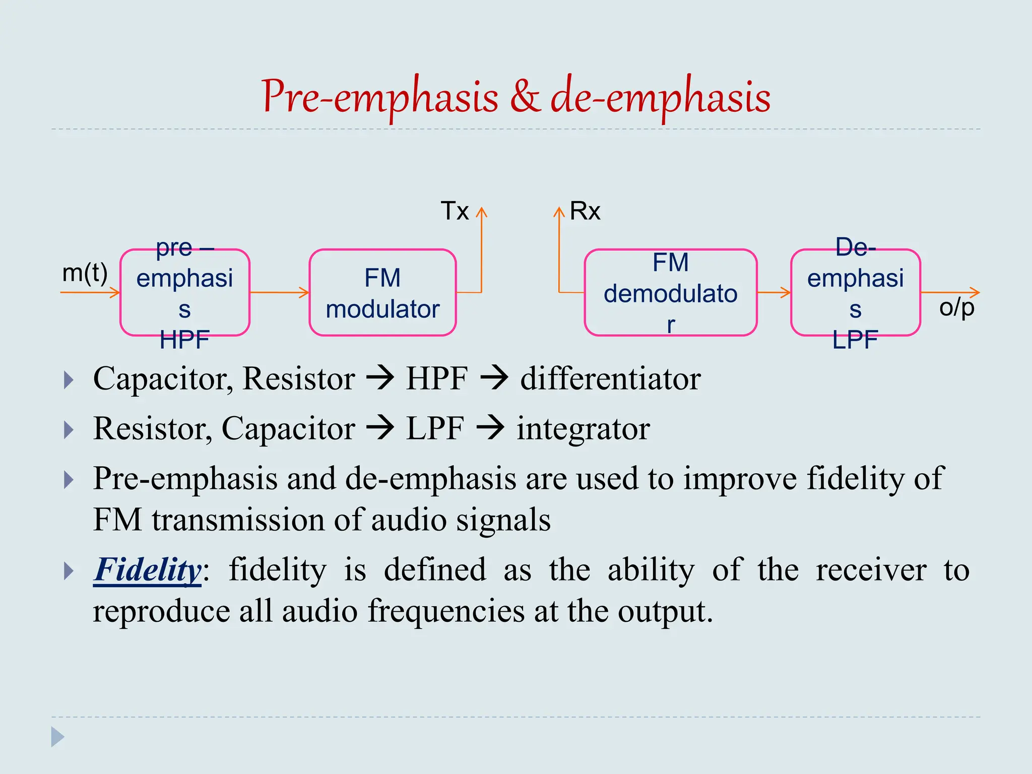
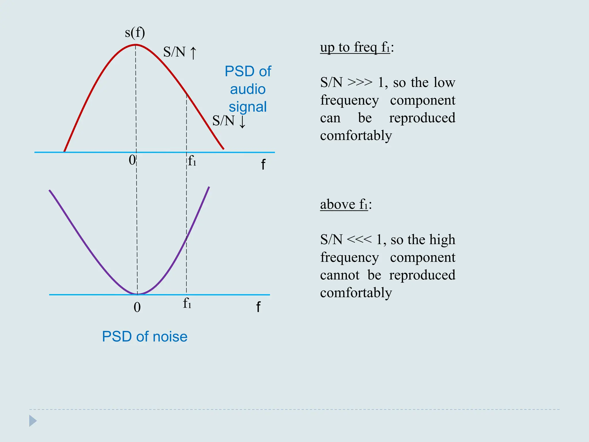
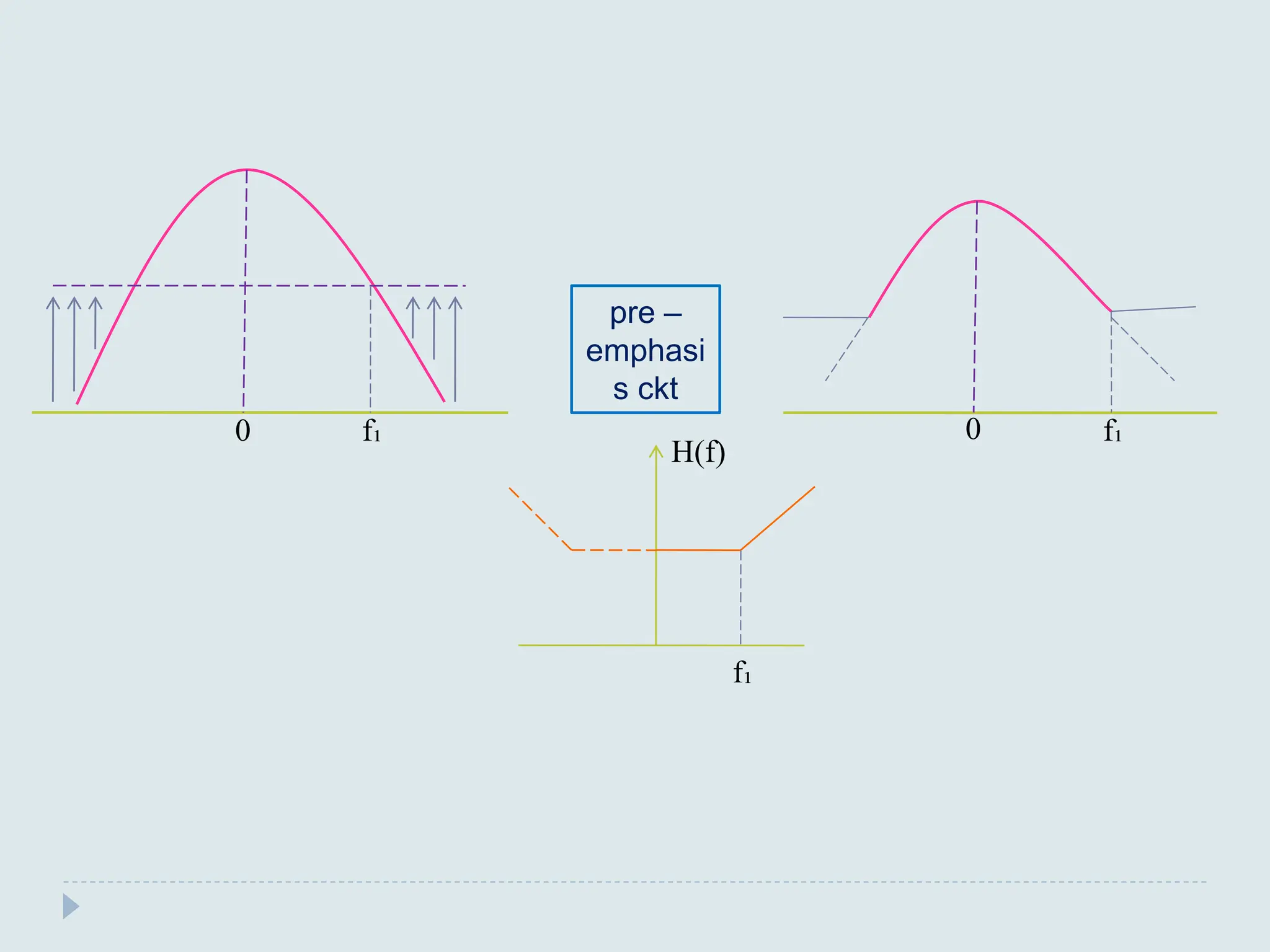
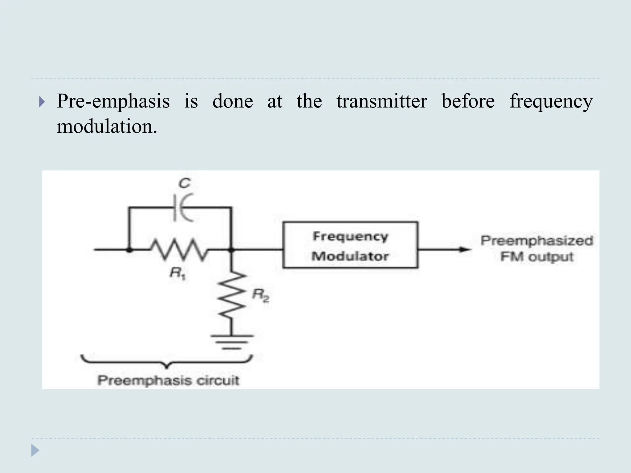
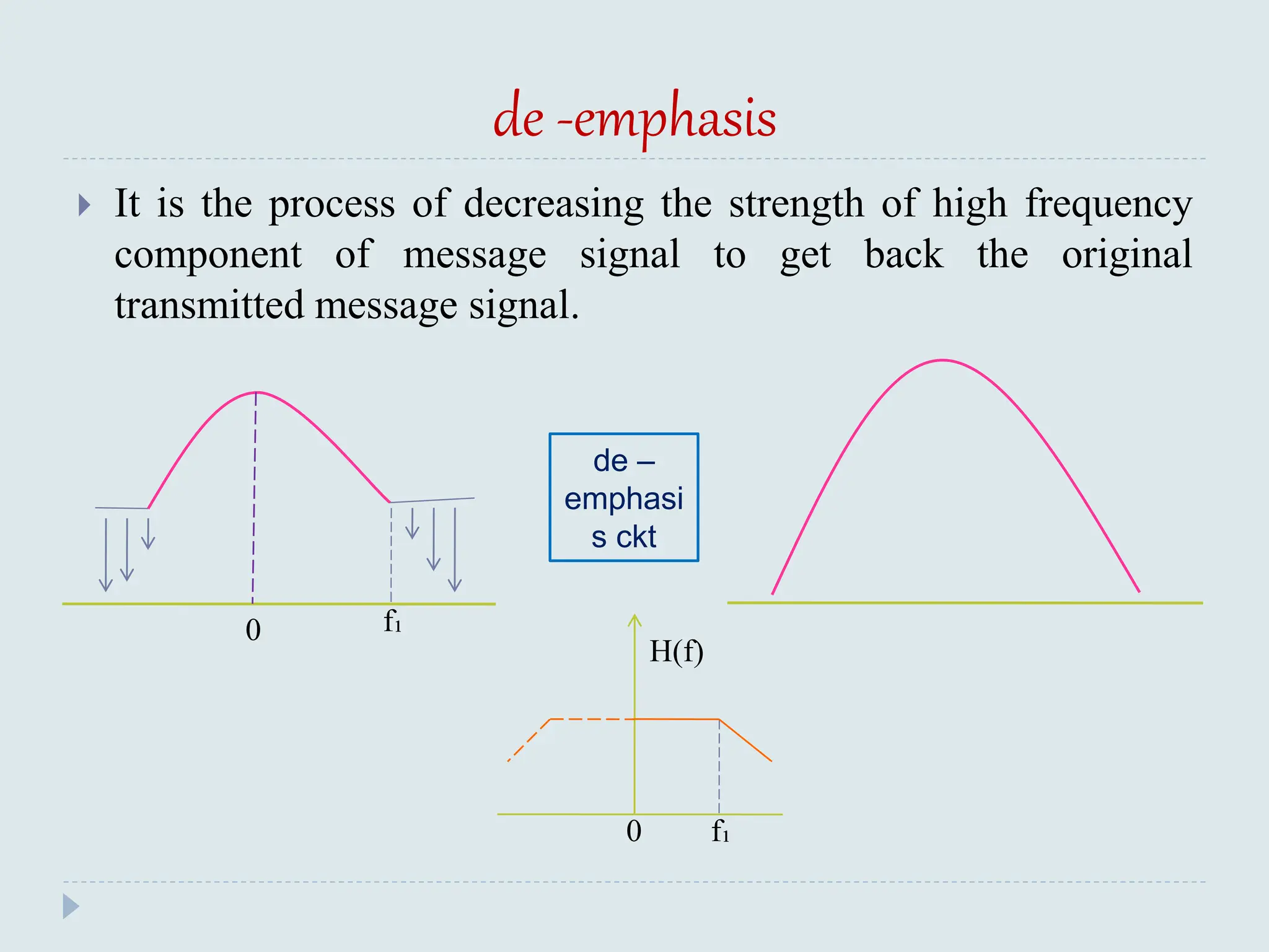
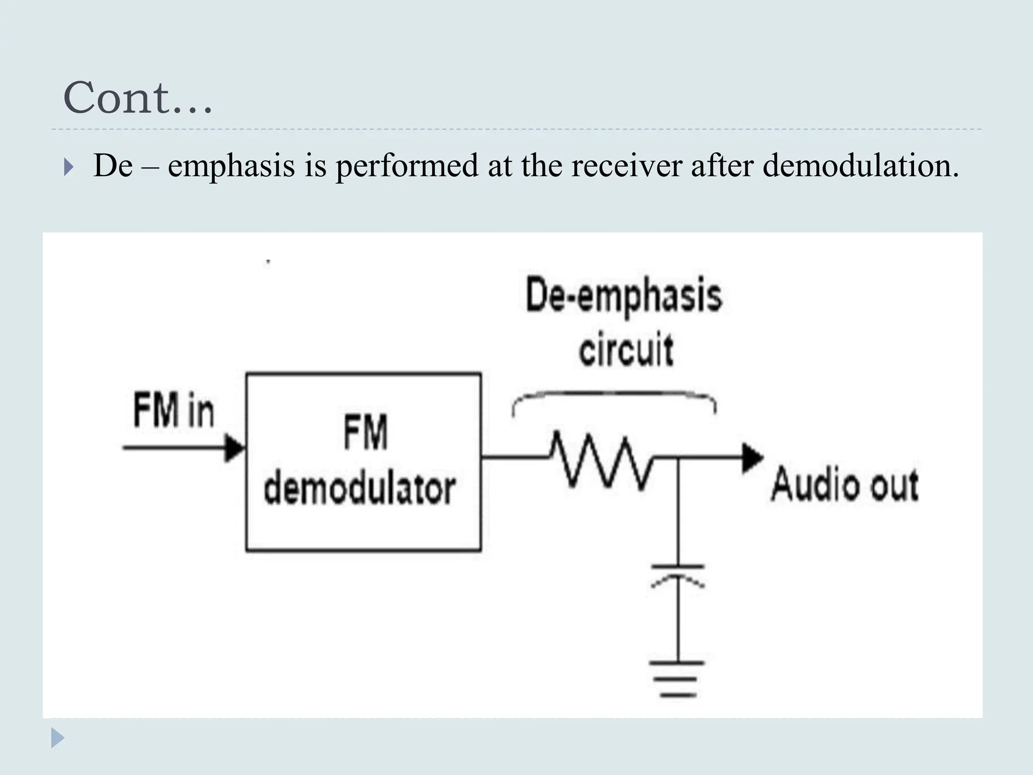
The document presents a course on analog communications, focusing extensively on noise, its classification into internal and external types, and details on various noise sources such as thermal, shot, and atmospheric noise. It also discusses receiver models, including their components and the impact of noise on signal quality, highlighting concepts like signal-to-noise ratio, figure of merit, and noise performance in different types of receivers like AM, FM, DSB-SC, and SSB-SC. Additionally, the document covers techniques like pre-emphasis and de-emphasis to improve fidelity in FM transmission and outlines key effects such as the capture effect in frequency modulation.


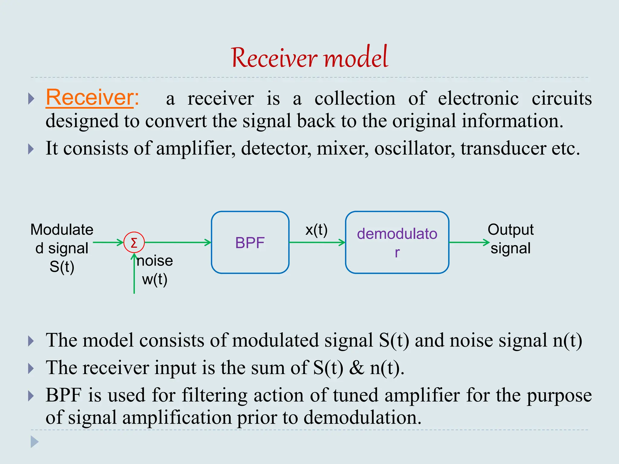

![Noise in AM receiver using envelope detector
In the case of AM signal both sidebands and the carrier is
transmitted.
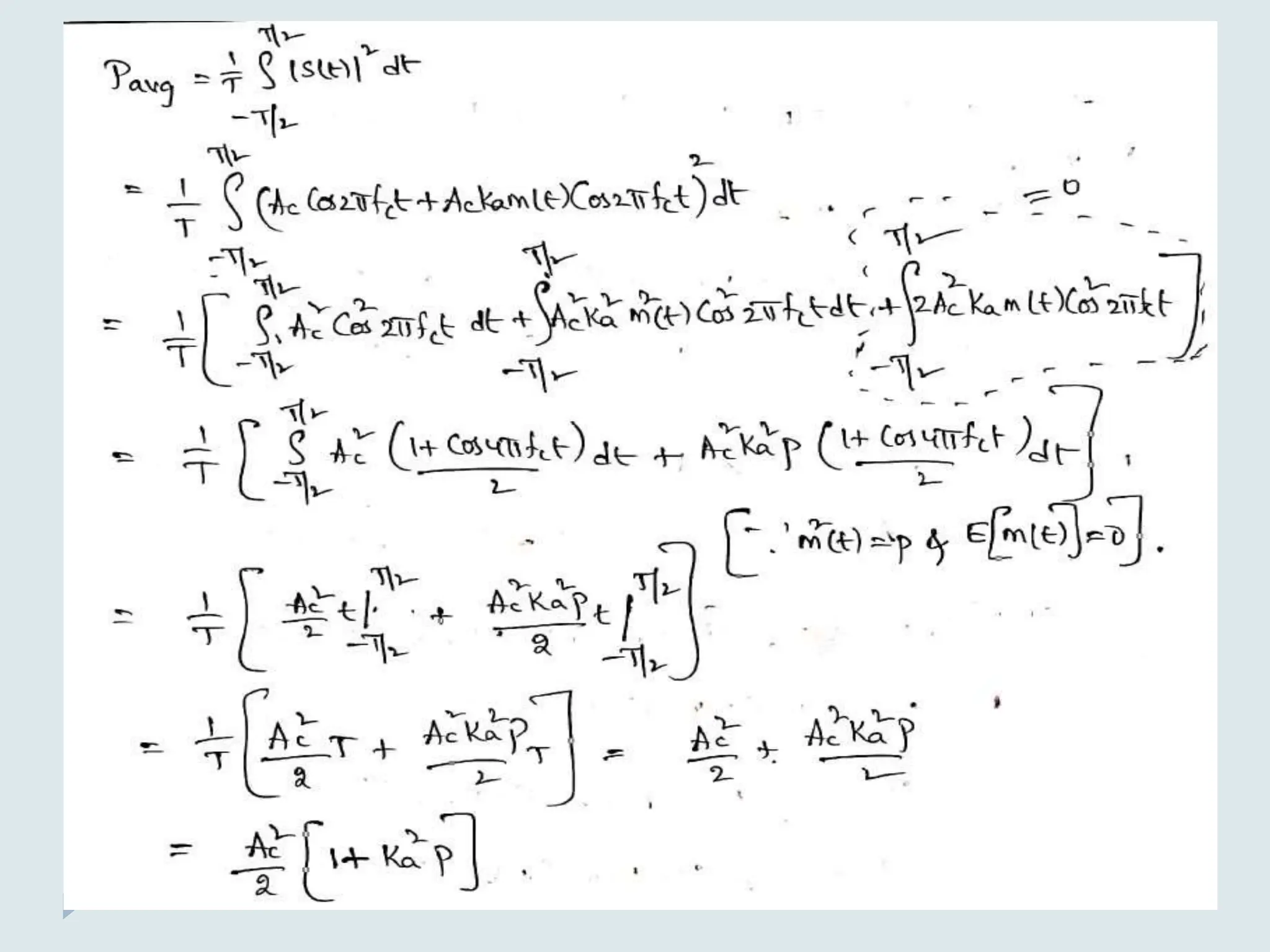
S(t) = Ac [1 + Ka m(t)] Cos(2πfct)
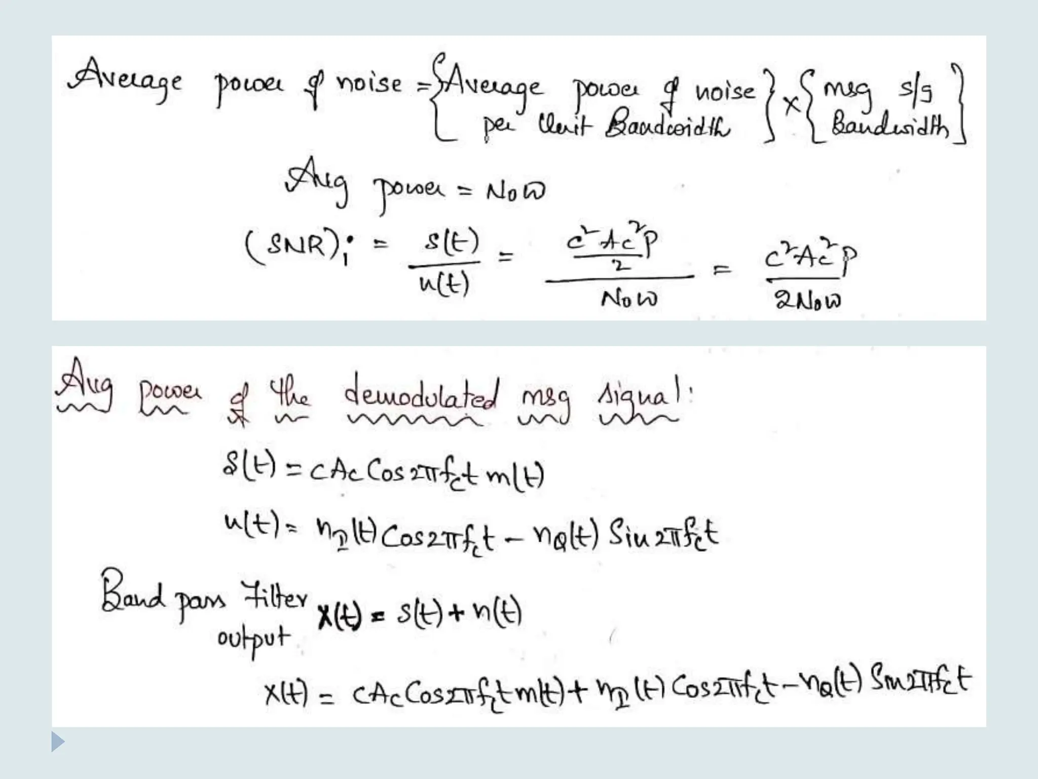
The average power of AM signal is calculated as follows
S(t) = Ac Cos(2πfct) + Ac Ka m(t) Cos(2πfct)
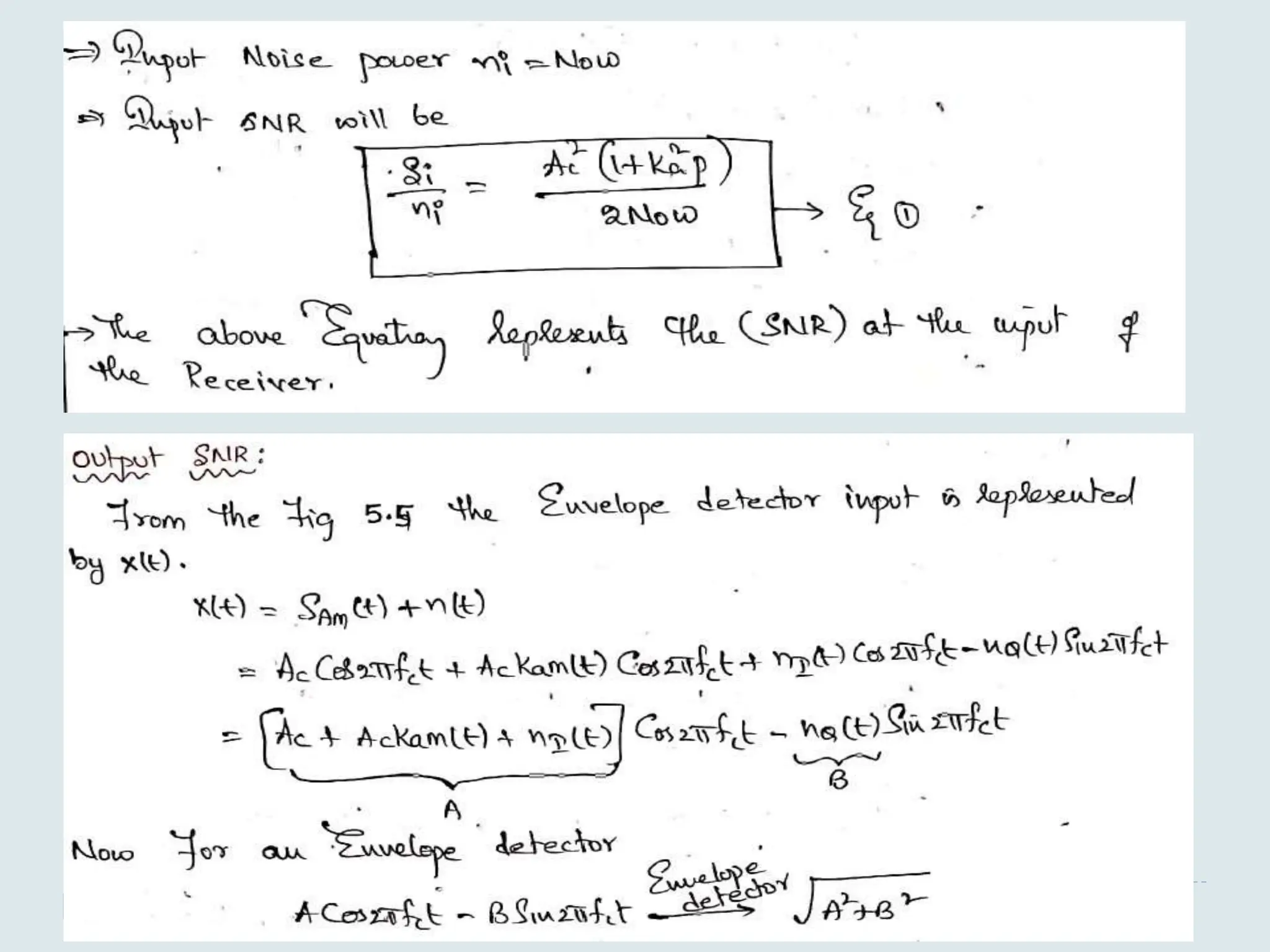
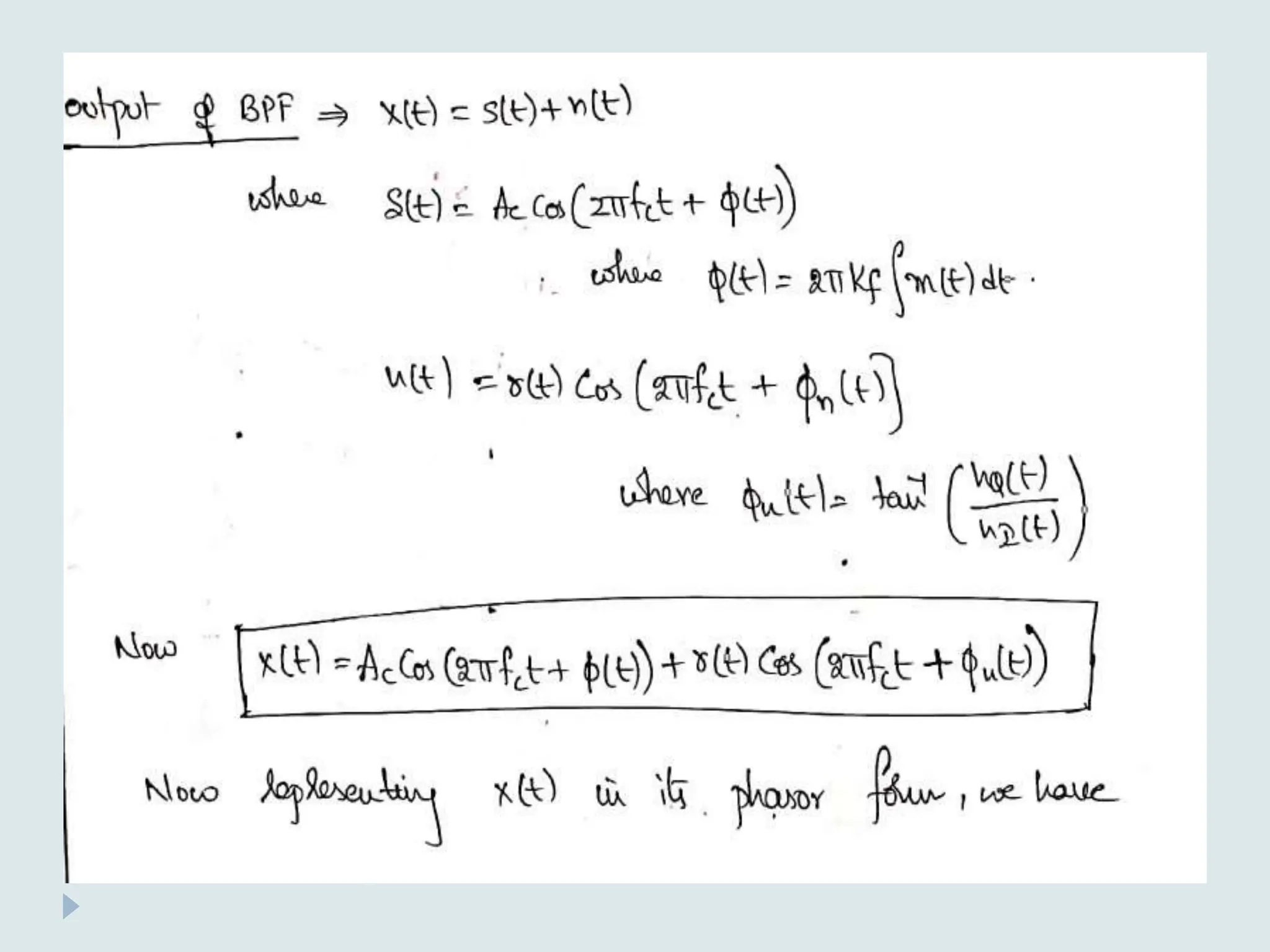
Σ BPF
Envelope
detector
x(t)
w(t)
y(t)
S(t)
AM
signal
o/p
signal
noise
signa
l Model of AM Receiver
+
+](https://image.slidesharecdn.com/unitvnoise-240508094613-d90cc507/75/Presentation-on-Noise-from-Analog-Communication-31-2048.jpg)