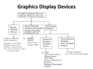
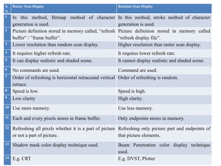
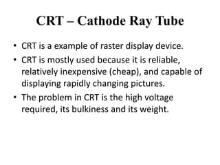
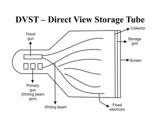
SlideShare a Scribd company logo
Graphics Display Devices –
CRT & DVST
Presented by
Asst. Prof. Aparna Joshi
Graphics Display Devices
Graphics Display Devices /
Inherent Memory Devices
Raster
Display
Device
Vector Refresh
Display/calligraphic
Display/Randam
Display Device
Flat Panel
Display
.
.
Display controller
video controller
Graphics controller/
Display processor/
Display coprocessor
E g.
E lectron gun
C RT (C athod R ay Tube)
.
Eg.. . Plotters
(
)
DVST
oirect View
storage Tube
. Emissive
Display/
Emitter/
Active
Non-emissive
Display/
Non- Emitter/
Passive
Eg..LED
(Light Emitting Diode )
Plasma Panel
Vaccum Fluroscent
Thin Film
electro juminiscent
Display
Display
.
.
.
(Light Modulating)
Eg. LCD (Liquid Crystal Display)
S.
N.
Raster Scan Display Random Scan Display
1 In this method, Bitmap method of character
generation is used.
In this method, stroke method of character
generation is used.
2 Picture definition stored in memory called, “refresh
buffer” / ”frame buffer”.
Picture definition stored in memory called
“refresh display file”.
3 Lower resolution than random scan display. Higher resolution than raster scan display.
4 It requires higher refresh rate. It requires lower refresh rate.
5 It can display realistic and shaded scene. It cannot display realistic and shaded scene.
6 No commands are used. Command are used.
7 Order of refreshing is horizontal retraceand vertical
retrace.
Order of refreshing is random.
8 Speed is low. Speed is high.
9 Low clarity High clarity.
10 Use more memory. Use less memory.
11 Each and every pixels stores in frame buffer. Only endpoints stores in memory.
12 Refreshing all pixels whether it is a part of picture
or not a part of picture.
Refreshing only picture part and endpoints of
that picture elements.
13 Shadow mask color display technique used. Beam Penetration color display technique
used.
14 E.g. CRT E.g. DVST, Plotter
CRT – Cathode Ray Tube
• CRT is a example of raster display device.
• CRT is mostly used because it is reliable,
relatively inexpensive (cheap), and capable of
displaying rapidly changing pictures.
• The problem in CRT is the high voltage
required, its bulkiness and its weight.
Construction and Working of CRT
• At the narrow end of sealed conical glass tube is an electron gun
that emits high velocity, finely focused beam of electrons.
• The other end i.e. face of CRT is more or less flat and is coated on
inside phosphor, which glows when electron beam strikes it.
• The energy of the beam can be controlled so as to vary the intensity
of light output and when necessary to cut off the light.
• A yoke or system of electromagnetic coil is mounted on the outside
of the tube.
• It deflects the electron beam to different parts of tube face when
currents pass through coils.
• A light output of the CRT phosphor falls off rapidly after the
electron beam has passed by and a steady picture is maintain by
tracing it out rapidly and repeatedly, generally this refresh process is
performed at least 60 times a second.
• The basic arrangement of the CRT as shown in fig.
CRT – Cathode Ray Tube
Elements of the CRT with Functions
a) Electron Gun:
• The electron gun makes use of electrostatic fields to focus
and accelerate the electron beam. The purpose of the
electron gun in the CRT is to produce an electron beam.
• A beam of electrons (Cathode rays), emitted by a electron
gun passes through focusing and deflection systems that
direct the beam toward specified positions on the phosphor
coated screen.
• The phosphor then emits a small spot of light at each
position contacted by the electron beam. Because the light
emitted by the phosphor fades very rapidly, some method is
needed for maintaining the screen picture.
• One way to keep the phosphor glowing is to redraw the
picture repeatedly by quickly directing the electron beam
back over the same points. This type of display is called,
“refresh CRT”.
• Electron gun contains separate parts:
i) Filament :-
It is also called as, “heater”. It is used to heat the cathode, so it emits
electrons. Heat is supplied to the cathode by directing a current through a
coil of wire, called, “the filament” inside the cylindrical cathode structure.
ii) Cathode :-
Surrounding the cathode is cylindrical metal control grid with a hole at one
end that allows electron to escape. After getting temperature or heat from the
filament, cathode starts electron flow from cathode to final anode or
phosphorus coating. Electron flow from cathode to final anode because
anode having positive 14,000 volts and there is attraction between them.
There is a vacuum or inert gases, not air present there. Function of cathode is
to give or to emit electrons when it will be heated by filament.
iii) Control Grid :-
Intensity of the electron beam is controlled by setting voltage levels on the
control grid, which is a metal cylinder that fits over the cathode. Control grid
is kept as lower potential than cathode by altering the control grid potential.
We can modify the rate of flow of electrons or beam current. Thus, control
the brightness of the image. Control grid is operated with negative logic.
When we will increase the negative voltage on the control grid, it will
reduce the number of electrons travelling/going to the front side of CRT.
Thus, we can control brightness using it.
b) Accelerating Grid /Screen Grid:
An accelerating grid or screen grid is combined with the focusing structure.
It consist of two metal plates mounted perpendicular to beam axis with
holes at their centers. Accelerating grid is used to control the speed of
electrons by changing positive voltage on it. Thus, we can control contrast
on the screen.
c) Focusing Grid:
Focusing grid containing two or more cylindrical metal plates at different
potential. It is used to control width of electron beam.
d) Deflection System / Yoke:
A set of coils or yokes mounted at the neck of tube forms part of deflection
system to pairs of coils are use one to control horizontal deflection and
other for vertical deflection.
Vertical yoke and horizontal yokes are used to move electron beam into
horizontal and vertical direction. Deflection of the electron beam can be
controlled either with electric fields or with magnetic fields. Two pairs of
coils are used, with the coils in each pair mounted on opposite sides of the
neck of the CRT. One pair is mounted on the top and bottom of the neck,
and the other pair is mounted on opposite sides of the neck. Horizontal
deflection is accomplished with one pair of coils, and vertical deflection by
the other pair.
e) Phosphorus Coating:
When electron beam hits on phosphorus coating, it will emit light on the
front side of picture tube. Spots of light are produced on the screen by the
transfer of the CRT beam energy to the phosphor.
Phosphorous used in graphics displays are P1, P4, P4 which normally
selected for their current characteristic and persistence. Persistence means
time for the brightness of point to drop to one tenth (1/10th ) of its initial
value. or Persistence means how much time the point emits light. Lower
persistence phosphors require higher refresh rates to maintain a picture on
the screen without flicker.
,
• Advantages of the CRT :-
• It is reliable
• It is relatively inexpensive (cheap)
• Capable of displaying rapidly changing
pictures
• Disadvantages of CRT :-
• High voltage required
• It is bulky and weighty
DVST – Direct View Storage Tube
• A direct view storage tube (DVST) stores the picture information
as a charge distribution just behind the phosphor coated system.
• Two electron guns are used in a DVST. One is the primary gun
which is used to store the picture pattern just behind the screen.
Another is flood gun which maintains picture display.
• The beam is designed not to write on a fine-mesh wire grid,
coated with dielectric and mounted on just behind the screen.
• A pattern of positive (+ ve) charge is deposited on the grid and
this pattern is transferred to phosphor by continuous flood of
electrons issuing from a separate flood gun.
• Just behind the storage mesh is a second grid, the collector,
whose main purpose is to smooth out the flow of flood electrons.
• These electrons passed through the collector at low velocity and
attracted to positively charged positions of storage mesh but
repelled by the rest.
• Advantages of DVST :-
Very complex picture can be displayed at very high
resolution without flickers, because no refreshing is
needed.
• Disadvantages of DVST :-
• DVST ordinarily do not display colors and selected parts
of the picture cannot be erased.
• To eliminate the picture section, the entire screen must
be erased and modified picture is redrawn. The erasing
and redrawing process can take several seconds for
complex pictures. For this reasons, storage displays
have not been largely used. They are replaced by the
raster system.
• A line written on the screen will remain visible upto an
hour before it fades from light.
Thank You

More Related Content

What's hot

Chapter 5b
Chapter 5bChapter 5b
Chapter 5b
Gabriel O'Brien
 
Video DIsplay Technologies
Video DIsplay TechnologiesVideo DIsplay Technologies
Video DIsplay Technologies
Varunjeet Singh Rekhi
 
CCD (Charge Coupled Device)
CCD (Charge Coupled Device)CCD (Charge Coupled Device)
CCD (Charge Coupled Device)
Sagar Reddy
 
Optical modulator (8,12,17,29)
Optical modulator (8,12,17,29)Optical modulator (8,12,17,29)
Optical modulator (8,12,17,29)
boneychatterjee
 
Computer graphics - colour crt and flat-panel displays
Computer graphics - colour crt and flat-panel displaysComputer graphics - colour crt and flat-panel displays
Computer graphics - colour crt and flat-panel displays
Vishnupriya T H
 
Cathode ray tube ~ankit
Cathode ray tube ~ankitCathode ray tube ~ankit
Cathode ray tube ~ankit
Ankit Sharma
 
fluoroscopy imaging
 fluoroscopy imaging  fluoroscopy imaging
fluoroscopy imaging
Estam Udith
 
Chapter 2b
Chapter 2bChapter 2b
Chapter 2b
Gabriel O'Brien
 
cathode ray tube
cathode ray tubecathode ray tube
cathode ray tube
wasim liam
 
Magneto optic devices
Magneto optic devicesMagneto optic devices
Magneto optic devices
vijayakumar sivaji
 
7. lecture=11 12 splitters, isolators
7. lecture=11 12 splitters, isolators7. lecture=11 12 splitters, isolators
7. lecture=11 12 splitters, isolators
HamidAwan14
 
External modulators
External modulatorsExternal modulators
External modulators
Suresh Jat
 
3. lecture=3 4 transmitter + modulators
3. lecture=3 4 transmitter + modulators3. lecture=3 4 transmitter + modulators
3. lecture=3 4 transmitter + modulators
HamidAwan14
 
Group 5 Wireless Oower
Group 5 Wireless OowerGroup 5 Wireless Oower
Group 5 Wireless OowerLalit Garg
 
6. lecture=9 10 filters
6. lecture=9 10 filters6. lecture=9 10 filters
6. lecture=9 10 filters
HamidAwan14
 
Charge coupled device(ccd)
Charge coupled device(ccd)Charge coupled device(ccd)
Charge coupled device(ccd)
Darshil Shah
 
4 laserdiodestruct
4 laserdiodestruct4 laserdiodestruct
4 laserdiodestruct
Neha Yadav
 
Video display devices
Video display devicesVideo display devices
Video display devices
shalinikarunakaran1
 
X ray machines - conventional and digital
X ray machines - conventional and digitalX ray machines - conventional and digital
X ray machines - conventional and digital
Urfeya Mirza
 

What's hot (20)

Cathoderaytube final
Cathoderaytube finalCathoderaytube final
Cathoderaytube final
 
Chapter 5b
Chapter 5bChapter 5b
Chapter 5b
 
Video DIsplay Technologies
Video DIsplay TechnologiesVideo DIsplay Technologies
Video DIsplay Technologies
 
CCD (Charge Coupled Device)
CCD (Charge Coupled Device)CCD (Charge Coupled Device)
CCD (Charge Coupled Device)
 
Optical modulator (8,12,17,29)
Optical modulator (8,12,17,29)Optical modulator (8,12,17,29)
Optical modulator (8,12,17,29)
 
Computer graphics - colour crt and flat-panel displays
Computer graphics - colour crt and flat-panel displaysComputer graphics - colour crt and flat-panel displays
Computer graphics - colour crt and flat-panel displays
 
Cathode ray tube ~ankit
Cathode ray tube ~ankitCathode ray tube ~ankit
Cathode ray tube ~ankit
 
fluoroscopy imaging
 fluoroscopy imaging  fluoroscopy imaging
fluoroscopy imaging
 
Chapter 2b
Chapter 2bChapter 2b
Chapter 2b
 
cathode ray tube
cathode ray tubecathode ray tube
cathode ray tube
 
Magneto optic devices
Magneto optic devicesMagneto optic devices
Magneto optic devices
 
7. lecture=11 12 splitters, isolators
7. lecture=11 12 splitters, isolators7. lecture=11 12 splitters, isolators
7. lecture=11 12 splitters, isolators
 
External modulators
External modulatorsExternal modulators
External modulators
 
3. lecture=3 4 transmitter + modulators
3. lecture=3 4 transmitter + modulators3. lecture=3 4 transmitter + modulators
3. lecture=3 4 transmitter + modulators
 
Group 5 Wireless Oower
Group 5 Wireless OowerGroup 5 Wireless Oower
Group 5 Wireless Oower
 
6. lecture=9 10 filters
6. lecture=9 10 filters6. lecture=9 10 filters
6. lecture=9 10 filters
 
Charge coupled device(ccd)
Charge coupled device(ccd)Charge coupled device(ccd)
Charge coupled device(ccd)
 
4 laserdiodestruct
4 laserdiodestruct4 laserdiodestruct
4 laserdiodestruct
 
Video display devices
Video display devicesVideo display devices
Video display devices
 
X ray machines - conventional and digital
X ray machines - conventional and digitalX ray machines - conventional and digital
X ray machines - conventional and digital
 

Similar to Presentation and output devices

Video display devices
Video display devicesVideo display devices
Video display devicesMohd Arif
 
Introduction to cathode Ray Tube.pptx
Introduction   to   cathode Ray Tube.pptxIntroduction   to   cathode Ray Tube.pptx
Introduction to cathode Ray Tube.pptx
RevathiJ10
 
5_6066813714177198739.pdf
5_6066813714177198739.pdf5_6066813714177198739.pdf
5_6066813714177198739.pdf
VanshdeepSingh28
 
Video display devices
Video display devicesVideo display devices
Video display devices
Pooja Dixit
 
ELECTRICAL AND ELECTRONICS MEASURING INSTRUMETNTS,CRO,CRT,PROBES,OSCILLOSCOPES
ELECTRICAL AND ELECTRONICS MEASURING INSTRUMETNTS,CRO,CRT,PROBES,OSCILLOSCOPESELECTRICAL AND ELECTRONICS MEASURING INSTRUMETNTS,CRO,CRT,PROBES,OSCILLOSCOPES
ELECTRICAL AND ELECTRONICS MEASURING INSTRUMETNTS,CRO,CRT,PROBES,OSCILLOSCOPES
AKSHIT KOHLI
 
2- devices crt computer graphics and multimedia.ppt
2- devices crt computer graphics and multimedia.ppt2- devices crt computer graphics and multimedia.ppt
2- devices crt computer graphics and multimedia.ppt
KumarVaibhav100
 
Cathode ray tube technology
Cathode ray tube technologyCathode ray tube technology
8259731.ppt
8259731.ppt8259731.ppt
8259731.ppt
ssuseraf60311
 
cathode ray oscilloscope
cathode ray oscilloscopecathode ray oscilloscope
cathode ray oscilloscope
prapti borthakur
 
Chapter two 1
Chapter two 1Chapter two 1
Chapter two 1
mahammed rashid
 
graphic terminal crt monitor
graphic terminal  crt monitorgraphic terminal  crt monitor
graphic terminal crt monitor
Jagilam Kumar
 
Display devices
Display devices Display devices
Display devices
St.Joseph's college
 
Understanding Lab Instruments
Understanding Lab InstrumentsUnderstanding Lab Instruments
Understanding Lab Instruments
Dattaraj Vidyasagar
 
CG MODULE 1 (S6 CSE)-1.pptx
CG MODULE 1 (S6 CSE)-1.pptxCG MODULE 1 (S6 CSE)-1.pptx
CG MODULE 1 (S6 CSE)-1.pptx
SayoojSukumaran1
 
CG MODULE 1 (S6 CSE).pptx
CG MODULE 1 (S6 CSE).pptxCG MODULE 1 (S6 CSE).pptx
CG MODULE 1 (S6 CSE).pptx
FahadSalim15
 
Computer Graphics display technologies(Computer graphics tutorials and tips)
Computer Graphics display technologies(Computer graphics tutorials and tips)Computer Graphics display technologies(Computer graphics tutorials and tips)
Computer Graphics display technologies(Computer graphics tutorials and tips)
Daroko blog(www.professionalbloggertricks.com)
 
Computer Graphics display technologies(Computer graphics tutorials)
Computer Graphics display technologies(Computer graphics tutorials)Computer Graphics display technologies(Computer graphics tutorials)
Computer Graphics display technologies(Computer graphics tutorials)
Daroko blog(www.professionalbloggertricks.com)
 
display devices.pptx
display devices.pptxdisplay devices.pptx
display devices.pptx
AseebKhan33
 
Cathode Ray Oscilloscope
Cathode Ray OscilloscopeCathode Ray Oscilloscope
Cathode Ray Oscilloscope
Ketan Nayak
 
cr srms1.pptx
cr srms1.pptxcr srms1.pptx
cr srms1.pptx
VirendraMaurya28
 

Similar to Presentation and output devices (20)

Video display devices
Video display devicesVideo display devices
Video display devices
 
Introduction to cathode Ray Tube.pptx
Introduction   to   cathode Ray Tube.pptxIntroduction   to   cathode Ray Tube.pptx
Introduction to cathode Ray Tube.pptx
 
5_6066813714177198739.pdf
5_6066813714177198739.pdf5_6066813714177198739.pdf
5_6066813714177198739.pdf
 
Video display devices
Video display devicesVideo display devices
Video display devices
 
ELECTRICAL AND ELECTRONICS MEASURING INSTRUMETNTS,CRO,CRT,PROBES,OSCILLOSCOPES
ELECTRICAL AND ELECTRONICS MEASURING INSTRUMETNTS,CRO,CRT,PROBES,OSCILLOSCOPESELECTRICAL AND ELECTRONICS MEASURING INSTRUMETNTS,CRO,CRT,PROBES,OSCILLOSCOPES
ELECTRICAL AND ELECTRONICS MEASURING INSTRUMETNTS,CRO,CRT,PROBES,OSCILLOSCOPES
 
2- devices crt computer graphics and multimedia.ppt
2- devices crt computer graphics and multimedia.ppt2- devices crt computer graphics and multimedia.ppt
2- devices crt computer graphics and multimedia.ppt
 
Cathode ray tube technology
Cathode ray tube technologyCathode ray tube technology
Cathode ray tube technology
 
8259731.ppt
8259731.ppt8259731.ppt
8259731.ppt
 
cathode ray oscilloscope
cathode ray oscilloscopecathode ray oscilloscope
cathode ray oscilloscope
 
Chapter two 1
Chapter two 1Chapter two 1
Chapter two 1
 
graphic terminal crt monitor
graphic terminal  crt monitorgraphic terminal  crt monitor
graphic terminal crt monitor
 
Display devices
Display devices Display devices
Display devices
 
Understanding Lab Instruments
Understanding Lab InstrumentsUnderstanding Lab Instruments
Understanding Lab Instruments
 
CG MODULE 1 (S6 CSE)-1.pptx
CG MODULE 1 (S6 CSE)-1.pptxCG MODULE 1 (S6 CSE)-1.pptx
CG MODULE 1 (S6 CSE)-1.pptx
 
CG MODULE 1 (S6 CSE).pptx
CG MODULE 1 (S6 CSE).pptxCG MODULE 1 (S6 CSE).pptx
CG MODULE 1 (S6 CSE).pptx
 
Computer Graphics display technologies(Computer graphics tutorials and tips)
Computer Graphics display technologies(Computer graphics tutorials and tips)Computer Graphics display technologies(Computer graphics tutorials and tips)
Computer Graphics display technologies(Computer graphics tutorials and tips)
 
Computer Graphics display technologies(Computer graphics tutorials)
Computer Graphics display technologies(Computer graphics tutorials)Computer Graphics display technologies(Computer graphics tutorials)
Computer Graphics display technologies(Computer graphics tutorials)
 
display devices.pptx
display devices.pptxdisplay devices.pptx
display devices.pptx
 
Cathode Ray Oscilloscope
Cathode Ray OscilloscopeCathode Ray Oscilloscope
Cathode Ray Oscilloscope
 
cr srms1.pptx
cr srms1.pptxcr srms1.pptx
cr srms1.pptx
 

Recently uploaded

Mammalian Pineal Body Structure and Also Functions
Mammalian Pineal Body Structure and Also FunctionsMammalian Pineal Body Structure and Also Functions
Mammalian Pineal Body Structure and Also Functions
YOGESH DOGRA
 
SCHIZOPHRENIA Disorder/ Brain Disorder.pdf
SCHIZOPHRENIA Disorder/ Brain Disorder.pdfSCHIZOPHRENIA Disorder/ Brain Disorder.pdf
SCHIZOPHRENIA Disorder/ Brain Disorder.pdf
SELF-EXPLANATORY
 
Structures and textures of metamorphic rocks
Structures and textures of metamorphic rocksStructures and textures of metamorphic rocks
Structures and textures of metamorphic rocks
kumarmathi863
 
In silico drugs analogue design: novobiocin analogues.pptx
In silico drugs analogue design: novobiocin analogues.pptxIn silico drugs analogue design: novobiocin analogues.pptx
In silico drugs analogue design: novobiocin analogues.pptx
AlaminAfendy1
 
Unveiling the Energy Potential of Marshmallow Deposits.pdf
Unveiling the Energy Potential of Marshmallow Deposits.pdfUnveiling the Energy Potential of Marshmallow Deposits.pdf
Unveiling the Energy Potential of Marshmallow Deposits.pdf
Erdal Coalmaker
 
Richard's aventures in two entangled wonderlands
Richard's aventures in two entangled wonderlandsRichard's aventures in two entangled wonderlands
Richard's aventures in two entangled wonderlands
Richard Gill
 
Penicillin...........................pptx
Penicillin...........................pptxPenicillin...........................pptx
Penicillin...........................pptx
Cherry
 
Richard's entangled aventures in wonderland
Richard's entangled aventures in wonderlandRichard's entangled aventures in wonderland
Richard's entangled aventures in wonderland
Richard Gill
 
Seminar of U.V. Spectroscopy by SAMIR PANDA
 Seminar of U.V. Spectroscopy by SAMIR PANDA Seminar of U.V. Spectroscopy by SAMIR PANDA
Seminar of U.V. Spectroscopy by SAMIR PANDA
SAMIR PANDA
 
Viksit bharat till 2047 India@2047.pptx
Viksit bharat till 2047  India@2047.pptxViksit bharat till 2047  India@2047.pptx
Viksit bharat till 2047 India@2047.pptx
rakeshsharma20142015
 
Lab report on liquid viscosity of glycerin
Lab report on liquid viscosity of glycerinLab report on liquid viscosity of glycerin
Lab report on liquid viscosity of glycerin
ossaicprecious19
 
RNA INTERFERENCE: UNRAVELING GENETIC SILENCING
RNA INTERFERENCE: UNRAVELING GENETIC SILENCINGRNA INTERFERENCE: UNRAVELING GENETIC SILENCING
RNA INTERFERENCE: UNRAVELING GENETIC SILENCING
AADYARAJPANDEY1
 
Nutraceutical market, scope and growth: Herbal drug technology
Nutraceutical market, scope and growth: Herbal drug technologyNutraceutical market, scope and growth: Herbal drug technology
Nutraceutical market, scope and growth: Herbal drug technology
Lokesh Patil
 
FAIR & AI Ready KGs for Explainable Predictions
FAIR & AI Ready KGs for Explainable PredictionsFAIR & AI Ready KGs for Explainable Predictions
FAIR & AI Ready KGs for Explainable Predictions
Michel Dumontier
 
insect taxonomy importance systematics and classification
insect taxonomy importance systematics and classificationinsect taxonomy importance systematics and classification
insect taxonomy importance systematics and classification
anitaento25
 
general properties of oerganologametal.ppt
general properties of oerganologametal.pptgeneral properties of oerganologametal.ppt
general properties of oerganologametal.ppt
IqrimaNabilatulhusni
 
Lateral Ventricles.pdf very easy good diagrams comprehensive
Lateral Ventricles.pdf very easy good diagrams comprehensiveLateral Ventricles.pdf very easy good diagrams comprehensive
Lateral Ventricles.pdf very easy good diagrams comprehensive
silvermistyshot
 
EY - Supply Chain Services 2018_template.pptx
EY - Supply Chain Services 2018_template.pptxEY - Supply Chain Services 2018_template.pptx
EY - Supply Chain Services 2018_template.pptx
AlguinaldoKong
 
Cancer cell metabolism: special Reference to Lactate Pathway
Cancer cell metabolism: special Reference to Lactate PathwayCancer cell metabolism: special Reference to Lactate Pathway
Cancer cell metabolism: special Reference to Lactate Pathway
AADYARAJPANDEY1
 
GBSN- Microbiology (Lab 3) Gram Staining
GBSN- Microbiology (Lab 3) Gram StainingGBSN- Microbiology (Lab 3) Gram Staining
GBSN- Microbiology (Lab 3) Gram Staining
Areesha Ahmad
 

Recently uploaded (20)

Mammalian Pineal Body Structure and Also Functions
Mammalian Pineal Body Structure and Also FunctionsMammalian Pineal Body Structure and Also Functions
Mammalian Pineal Body Structure and Also Functions
 
SCHIZOPHRENIA Disorder/ Brain Disorder.pdf
SCHIZOPHRENIA Disorder/ Brain Disorder.pdfSCHIZOPHRENIA Disorder/ Brain Disorder.pdf
SCHIZOPHRENIA Disorder/ Brain Disorder.pdf
 
Structures and textures of metamorphic rocks
Structures and textures of metamorphic rocksStructures and textures of metamorphic rocks
Structures and textures of metamorphic rocks
 
In silico drugs analogue design: novobiocin analogues.pptx
In silico drugs analogue design: novobiocin analogues.pptxIn silico drugs analogue design: novobiocin analogues.pptx
In silico drugs analogue design: novobiocin analogues.pptx
 
Unveiling the Energy Potential of Marshmallow Deposits.pdf
Unveiling the Energy Potential of Marshmallow Deposits.pdfUnveiling the Energy Potential of Marshmallow Deposits.pdf
Unveiling the Energy Potential of Marshmallow Deposits.pdf
 
Richard's aventures in two entangled wonderlands
Richard's aventures in two entangled wonderlandsRichard's aventures in two entangled wonderlands
Richard's aventures in two entangled wonderlands
 
Penicillin...........................pptx
Penicillin...........................pptxPenicillin...........................pptx
Penicillin...........................pptx
 
Richard's entangled aventures in wonderland
Richard's entangled aventures in wonderlandRichard's entangled aventures in wonderland
Richard's entangled aventures in wonderland
 
Seminar of U.V. Spectroscopy by SAMIR PANDA
 Seminar of U.V. Spectroscopy by SAMIR PANDA Seminar of U.V. Spectroscopy by SAMIR PANDA
Seminar of U.V. Spectroscopy by SAMIR PANDA
 
Viksit bharat till 2047 India@2047.pptx
Viksit bharat till 2047  India@2047.pptxViksit bharat till 2047  India@2047.pptx
Viksit bharat till 2047 India@2047.pptx
 
Lab report on liquid viscosity of glycerin
Lab report on liquid viscosity of glycerinLab report on liquid viscosity of glycerin
Lab report on liquid viscosity of glycerin
 
RNA INTERFERENCE: UNRAVELING GENETIC SILENCING
RNA INTERFERENCE: UNRAVELING GENETIC SILENCINGRNA INTERFERENCE: UNRAVELING GENETIC SILENCING
RNA INTERFERENCE: UNRAVELING GENETIC SILENCING
 
Nutraceutical market, scope and growth: Herbal drug technology
Nutraceutical market, scope and growth: Herbal drug technologyNutraceutical market, scope and growth: Herbal drug technology
Nutraceutical market, scope and growth: Herbal drug technology
 
FAIR & AI Ready KGs for Explainable Predictions
FAIR & AI Ready KGs for Explainable PredictionsFAIR & AI Ready KGs for Explainable Predictions
FAIR & AI Ready KGs for Explainable Predictions
 
insect taxonomy importance systematics and classification
insect taxonomy importance systematics and classificationinsect taxonomy importance systematics and classification
insect taxonomy importance systematics and classification
 
general properties of oerganologametal.ppt
general properties of oerganologametal.pptgeneral properties of oerganologametal.ppt
general properties of oerganologametal.ppt
 
Lateral Ventricles.pdf very easy good diagrams comprehensive
Lateral Ventricles.pdf very easy good diagrams comprehensiveLateral Ventricles.pdf very easy good diagrams comprehensive
Lateral Ventricles.pdf very easy good diagrams comprehensive
 
EY - Supply Chain Services 2018_template.pptx
EY - Supply Chain Services 2018_template.pptxEY - Supply Chain Services 2018_template.pptx
EY - Supply Chain Services 2018_template.pptx
 
Cancer cell metabolism: special Reference to Lactate Pathway
Cancer cell metabolism: special Reference to Lactate PathwayCancer cell metabolism: special Reference to Lactate Pathway
Cancer cell metabolism: special Reference to Lactate Pathway
 
GBSN- Microbiology (Lab 3) Gram Staining
GBSN- Microbiology (Lab 3) Gram StainingGBSN- Microbiology (Lab 3) Gram Staining
GBSN- Microbiology (Lab 3) Gram Staining
 

Presentation and output devices

  • 1. Graphics Display Devices – CRT & DVST Presented by Asst. Prof. Aparna Joshi
  • 2. Graphics Display Devices Graphics Display Devices / Inherent Memory Devices Raster Display Device Vector Refresh Display/calligraphic Display/Randam Display Device Flat Panel Display . . Display controller video controller Graphics controller/ Display processor/ Display coprocessor E g. E lectron gun C RT (C athod R ay Tube) . Eg.. . Plotters ( ) DVST oirect View storage Tube . Emissive Display/ Emitter/ Active Non-emissive Display/ Non- Emitter/ Passive Eg..LED (Light Emitting Diode ) Plasma Panel Vaccum Fluroscent Thin Film electro juminiscent Display Display . . . (Light Modulating) Eg. LCD (Liquid Crystal Display)
  • 3. S. N. Raster Scan Display Random Scan Display 1 In this method, Bitmap method of character generation is used. In this method, stroke method of character generation is used. 2 Picture definition stored in memory called, “refresh buffer” / ”frame buffer”. Picture definition stored in memory called “refresh display file”. 3 Lower resolution than random scan display. Higher resolution than raster scan display. 4 It requires higher refresh rate. It requires lower refresh rate. 5 It can display realistic and shaded scene. It cannot display realistic and shaded scene. 6 No commands are used. Command are used. 7 Order of refreshing is horizontal retraceand vertical retrace. Order of refreshing is random. 8 Speed is low. Speed is high. 9 Low clarity High clarity. 10 Use more memory. Use less memory. 11 Each and every pixels stores in frame buffer. Only endpoints stores in memory. 12 Refreshing all pixels whether it is a part of picture or not a part of picture. Refreshing only picture part and endpoints of that picture elements. 13 Shadow mask color display technique used. Beam Penetration color display technique used. 14 E.g. CRT E.g. DVST, Plotter
  • 4. CRT – Cathode Ray Tube • CRT is a example of raster display device. • CRT is mostly used because it is reliable, relatively inexpensive (cheap), and capable of displaying rapidly changing pictures. • The problem in CRT is the high voltage required, its bulkiness and its weight.
  • 5. Construction and Working of CRT • At the narrow end of sealed conical glass tube is an electron gun that emits high velocity, finely focused beam of electrons. • The other end i.e. face of CRT is more or less flat and is coated on inside phosphor, which glows when electron beam strikes it. • The energy of the beam can be controlled so as to vary the intensity of light output and when necessary to cut off the light. • A yoke or system of electromagnetic coil is mounted on the outside of the tube. • It deflects the electron beam to different parts of tube face when currents pass through coils. • A light output of the CRT phosphor falls off rapidly after the electron beam has passed by and a steady picture is maintain by tracing it out rapidly and repeatedly, generally this refresh process is performed at least 60 times a second. • The basic arrangement of the CRT as shown in fig.
  • 6. CRT – Cathode Ray Tube
  • 7. Elements of the CRT with Functions a) Electron Gun: • The electron gun makes use of electrostatic fields to focus and accelerate the electron beam. The purpose of the electron gun in the CRT is to produce an electron beam. • A beam of electrons (Cathode rays), emitted by a electron gun passes through focusing and deflection systems that direct the beam toward specified positions on the phosphor coated screen. • The phosphor then emits a small spot of light at each position contacted by the electron beam. Because the light emitted by the phosphor fades very rapidly, some method is needed for maintaining the screen picture. • One way to keep the phosphor glowing is to redraw the picture repeatedly by quickly directing the electron beam back over the same points. This type of display is called, “refresh CRT”.
  • 8. • Electron gun contains separate parts: i) Filament :- It is also called as, “heater”. It is used to heat the cathode, so it emits electrons. Heat is supplied to the cathode by directing a current through a coil of wire, called, “the filament” inside the cylindrical cathode structure. ii) Cathode :- Surrounding the cathode is cylindrical metal control grid with a hole at one end that allows electron to escape. After getting temperature or heat from the filament, cathode starts electron flow from cathode to final anode or phosphorus coating. Electron flow from cathode to final anode because anode having positive 14,000 volts and there is attraction between them. There is a vacuum or inert gases, not air present there. Function of cathode is to give or to emit electrons when it will be heated by filament. iii) Control Grid :- Intensity of the electron beam is controlled by setting voltage levels on the control grid, which is a metal cylinder that fits over the cathode. Control grid is kept as lower potential than cathode by altering the control grid potential. We can modify the rate of flow of electrons or beam current. Thus, control the brightness of the image. Control grid is operated with negative logic. When we will increase the negative voltage on the control grid, it will reduce the number of electrons travelling/going to the front side of CRT. Thus, we can control brightness using it.
  • 9. b) Accelerating Grid /Screen Grid: An accelerating grid or screen grid is combined with the focusing structure. It consist of two metal plates mounted perpendicular to beam axis with holes at their centers. Accelerating grid is used to control the speed of electrons by changing positive voltage on it. Thus, we can control contrast on the screen. c) Focusing Grid: Focusing grid containing two or more cylindrical metal plates at different potential. It is used to control width of electron beam. d) Deflection System / Yoke: A set of coils or yokes mounted at the neck of tube forms part of deflection system to pairs of coils are use one to control horizontal deflection and other for vertical deflection. Vertical yoke and horizontal yokes are used to move electron beam into horizontal and vertical direction. Deflection of the electron beam can be controlled either with electric fields or with magnetic fields. Two pairs of coils are used, with the coils in each pair mounted on opposite sides of the neck of the CRT. One pair is mounted on the top and bottom of the neck, and the other pair is mounted on opposite sides of the neck. Horizontal deflection is accomplished with one pair of coils, and vertical deflection by the other pair.
  • 10. e) Phosphorus Coating: When electron beam hits on phosphorus coating, it will emit light on the front side of picture tube. Spots of light are produced on the screen by the transfer of the CRT beam energy to the phosphor. Phosphorous used in graphics displays are P1, P4, P4 which normally selected for their current characteristic and persistence. Persistence means time for the brightness of point to drop to one tenth (1/10th ) of its initial value. or Persistence means how much time the point emits light. Lower persistence phosphors require higher refresh rates to maintain a picture on the screen without flicker. ,
  • 11. • Advantages of the CRT :- • It is reliable • It is relatively inexpensive (cheap) • Capable of displaying rapidly changing pictures • Disadvantages of CRT :- • High voltage required • It is bulky and weighty
  • 12. DVST – Direct View Storage Tube
  • 13. DVST – Direct View Storage Tube • A direct view storage tube (DVST) stores the picture information as a charge distribution just behind the phosphor coated system. • Two electron guns are used in a DVST. One is the primary gun which is used to store the picture pattern just behind the screen. Another is flood gun which maintains picture display. • The beam is designed not to write on a fine-mesh wire grid, coated with dielectric and mounted on just behind the screen. • A pattern of positive (+ ve) charge is deposited on the grid and this pattern is transferred to phosphor by continuous flood of electrons issuing from a separate flood gun. • Just behind the storage mesh is a second grid, the collector, whose main purpose is to smooth out the flow of flood electrons. • These electrons passed through the collector at low velocity and attracted to positively charged positions of storage mesh but repelled by the rest.
  • 14. • Advantages of DVST :- Very complex picture can be displayed at very high resolution without flickers, because no refreshing is needed. • Disadvantages of DVST :- • DVST ordinarily do not display colors and selected parts of the picture cannot be erased. • To eliminate the picture section, the entire screen must be erased and modified picture is redrawn. The erasing and redrawing process can take several seconds for complex pictures. For this reasons, storage displays have not been largely used. They are replaced by the raster system. • A line written on the screen will remain visible upto an hour before it fades from light.