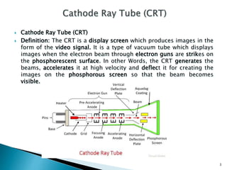
Prof. Neeraj Bhargava
Pooja Dixit
Department of Computer Science
School of Engineering & System Sciences
MDS, University Ajmer, Rajasthan, India
1
The display devices are known as output devices. The most commonly
used output device in a graphics video monitor. The operations of most
video monitors are based on the standard cathode-ray-tube (CRT) design.
How the Interactive Graphics display works
The modern graphics display is extremely simple in construction. It
consists of three components:
1- A digital memory, or frame buffer, in which the displayed Image is
stored as a matrix
of intensity values.
2- A monitor
3- A display controller, which is a simple interface that passes the contents
of the frame buffer to the monitor. Inside the frame buffer the image is
stored as a pattern of binary digital numbers, which represent a
rectangular array of picture elements, or pixel. The pixel is the smallest
addressable screen element. In the Simplest case where we wish to store
only black and white images, we can represent black pixels by 0's in the
frame buffer and white Pixels by 1's. The display controller simply reads
each successive byte of data from the frame buffer and converts each 0
and 1 to the corresponding video signal. This signal is then fed to the
monitor. If we wish to change the displayed picture all we need to do is
to change of modify the frame buffer contents to represent the new
pattern of pixels.
2
 Cathode Ray Tube (CRT)
 Definition: The CRT is a display screen which produces images in the
form of the video signal. It is a type of vacuum tube which displays
images when the electron beam through electron guns are strikes on
the phosphorescent surface. In other Words, the CRT generates the
beams, accelerates it at high velocity and deflect it for creating the
images on the phosphorous screen so that the beam becomes
visible.
3
 The working of CRT depends on the movement of electrons
beams. The electron guns generate sharply focused electrons
which are accelerated at high voltage. This high-velocity
electron beam when strikes on the fluorescent screen creates
luminous spot
 After exiting from the electron gun, the beam passes through
the pairs of electrostatic deflection plate. These plates
deflected the beams when the voltage applied across it. The
one pair of plate moves the beam upward and the second pair
of plate moves the beam from one side to another. The
horizontal and vertical movement of the electron are
independent of each other, and hence the electron beam
positioned anywhere on the screen.
 The working parts of a CRT are enclosed in a vacuum glass
envelope so that the emitted electron can easily move freely
from one end of the tube to the other.
4
 The primary components are the heated metal cathode
and a control grid.
 The heat is supplied to the cathode (by passing current
through the filament). This way the electrons get heated
up and start getting ejected out of the cathode filament.
 This stream of negatively charged electrons is accelerated
towards the phosphor screen by supplying a high positive
voltage.
 This acceleration is generally produced by means of an
accelerating anode.
 Next component is the Focusing System, which is used to
force the electron beam to converge to small spot on the
screen.
 If there will not be any focusing system, the electrons will
be scattered because of their own repulsions and hence we
won’t get a sharp image of the object.
 This focusing can be either by means of electrostatic fields
or magnetic fields.
5
 Electrostatic Deflection –
The electron beam (cathode rays) passes through a highly
positively charged metal cylinder that forms an electrostatic
lens. This electrostatic lens focuses the cathode rays to the
center of the screen in the same way like an optical lens
focuses the beam of light. Two pairs of parallel plates are
mounted inside the CRT tube.
 Magnetic Deflection –
Here, two pairs of coils are used. One pair is mounted on the
top and bottom of the CRT tube, and the other pair on the two
opposite sides. The magnetic field produced by both these
pairs is such that a force is generated on the electron beam in a
direction which is perpendicular to both the direction of
magnetic field, and to the direction of flow of the beam. One
pair is mounted horizontally and the other vertically.
6
Electron Guns
Red Input
Green
Input
Blue Input
Deflection
Yoke
Shadow Mask
Red, Blue,
and Green
Phosphor Dots
CRT
7
•Shadow mask has one small hole for each phosphor triad.
•Holes are precisely aligned with respect to both the triads and the
electron guns, so that each dot is exposed to electrons from only
one gun.
•The number of electrons in each beam controls the amount of red,
blue and green light generated by the triad.
SHADOW MASK
Red
Green
Blue
Convergence
Point
Phosphor Dot
Screen
8
 Dot Pitch –the spacing between pixels on a CRT, measured in
millimeters. Generally, the lower the number, the more
detailed the image.
9

Video display devices

  • 1.
    Prof. Neeraj Bhargava PoojaDixit Department of Computer Science School of Engineering & System Sciences MDS, University Ajmer, Rajasthan, India 1
  • 2.
    The display devicesare known as output devices. The most commonly used output device in a graphics video monitor. The operations of most video monitors are based on the standard cathode-ray-tube (CRT) design. How the Interactive Graphics display works The modern graphics display is extremely simple in construction. It consists of three components: 1- A digital memory, or frame buffer, in which the displayed Image is stored as a matrix of intensity values. 2- A monitor 3- A display controller, which is a simple interface that passes the contents of the frame buffer to the monitor. Inside the frame buffer the image is stored as a pattern of binary digital numbers, which represent a rectangular array of picture elements, or pixel. The pixel is the smallest addressable screen element. In the Simplest case where we wish to store only black and white images, we can represent black pixels by 0's in the frame buffer and white Pixels by 1's. The display controller simply reads each successive byte of data from the frame buffer and converts each 0 and 1 to the corresponding video signal. This signal is then fed to the monitor. If we wish to change the displayed picture all we need to do is to change of modify the frame buffer contents to represent the new pattern of pixels. 2
  • 3.
     Cathode RayTube (CRT)  Definition: The CRT is a display screen which produces images in the form of the video signal. It is a type of vacuum tube which displays images when the electron beam through electron guns are strikes on the phosphorescent surface. In other Words, the CRT generates the beams, accelerates it at high velocity and deflect it for creating the images on the phosphorous screen so that the beam becomes visible. 3
  • 4.
     The workingof CRT depends on the movement of electrons beams. The electron guns generate sharply focused electrons which are accelerated at high voltage. This high-velocity electron beam when strikes on the fluorescent screen creates luminous spot  After exiting from the electron gun, the beam passes through the pairs of electrostatic deflection plate. These plates deflected the beams when the voltage applied across it. The one pair of plate moves the beam upward and the second pair of plate moves the beam from one side to another. The horizontal and vertical movement of the electron are independent of each other, and hence the electron beam positioned anywhere on the screen.  The working parts of a CRT are enclosed in a vacuum glass envelope so that the emitted electron can easily move freely from one end of the tube to the other. 4
  • 5.
     The primarycomponents are the heated metal cathode and a control grid.  The heat is supplied to the cathode (by passing current through the filament). This way the electrons get heated up and start getting ejected out of the cathode filament.  This stream of negatively charged electrons is accelerated towards the phosphor screen by supplying a high positive voltage.  This acceleration is generally produced by means of an accelerating anode.  Next component is the Focusing System, which is used to force the electron beam to converge to small spot on the screen.  If there will not be any focusing system, the electrons will be scattered because of their own repulsions and hence we won’t get a sharp image of the object.  This focusing can be either by means of electrostatic fields or magnetic fields. 5
  • 6.
     Electrostatic Deflection– The electron beam (cathode rays) passes through a highly positively charged metal cylinder that forms an electrostatic lens. This electrostatic lens focuses the cathode rays to the center of the screen in the same way like an optical lens focuses the beam of light. Two pairs of parallel plates are mounted inside the CRT tube.  Magnetic Deflection – Here, two pairs of coils are used. One pair is mounted on the top and bottom of the CRT tube, and the other pair on the two opposite sides. The magnetic field produced by both these pairs is such that a force is generated on the electron beam in a direction which is perpendicular to both the direction of magnetic field, and to the direction of flow of the beam. One pair is mounted horizontally and the other vertically. 6
  • 7.
    Electron Guns Red Input Green Input BlueInput Deflection Yoke Shadow Mask Red, Blue, and Green Phosphor Dots CRT 7
  • 8.
    •Shadow mask hasone small hole for each phosphor triad. •Holes are precisely aligned with respect to both the triads and the electron guns, so that each dot is exposed to electrons from only one gun. •The number of electrons in each beam controls the amount of red, blue and green light generated by the triad. SHADOW MASK Red Green Blue Convergence Point Phosphor Dot Screen 8
  • 9.
     Dot Pitch–the spacing between pixels on a CRT, measured in millimeters. Generally, the lower the number, the more detailed the image. 9