Download to read offline

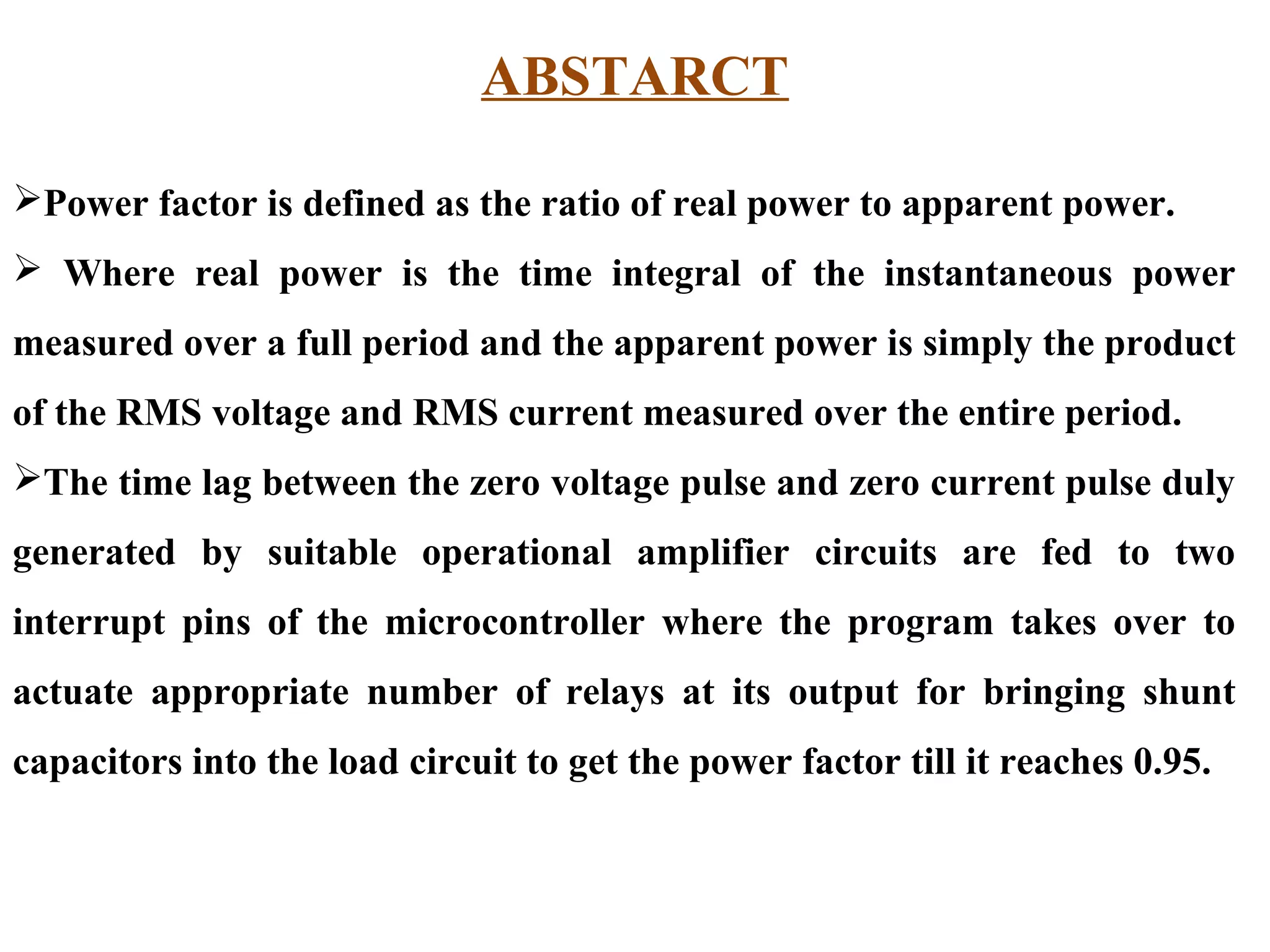


The document describes a project that uses a microcontroller to automatically engage the appropriate number of shunt capacitors for an inductive load to improve the power factor to 0.95 or greater. The microcontroller measures the time lag between the voltage and current pulses using operational amplifiers, then uses this information to actuate relays that connect shunt capacitors to the load circuit as needed. Key hardware components include the microcontroller, relays, relay drivers, current transformers, and shunt capacitors.


![Seller Deck - Presentation [Concert L2].PPTX](https://cdn.slidesharecdn.com/ss_thumbnails/sellerdeck-presentationconcertl2-251219171156-24982daf-thumbnail.jpg?width=640&height=640&fit=bounds)


