Downloaded 136 times
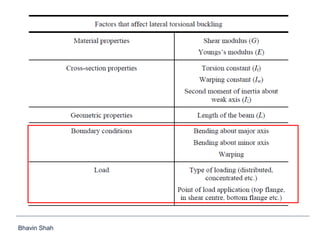
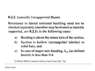


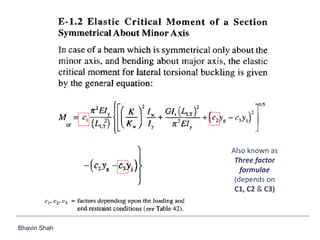
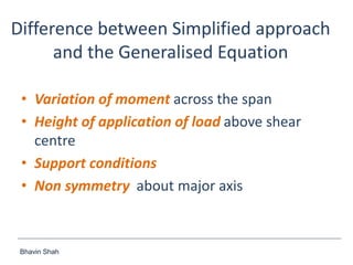
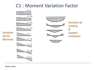
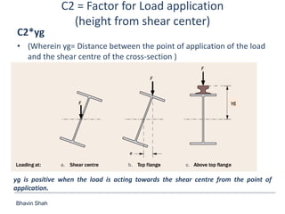
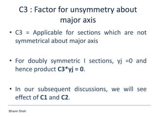

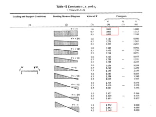
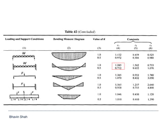
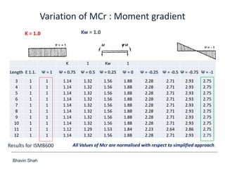
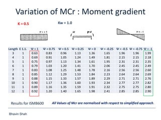
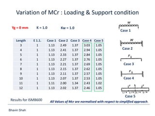
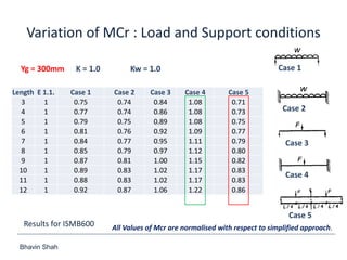
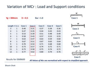
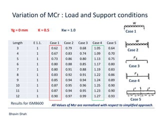
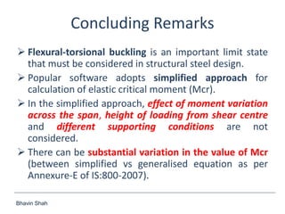

The document discusses elastic flexural-torsional buckling as a critical limit state in structural steel design, including the simplified approach outlined in IS:800-2007 and how popular software implements it. It highlights the variations in calculated elastic critical moments (Mcr) between the simplified approach and the generalised equations, emphasizing the impacts of moment variation, load height from the shear centre, and support conditions. The presentation concludes with plans to address queries related to IS:800-2007 and encourages collaboration between engineers and technical committees.


