Design of a modified leaf spring with an integrated damping system for added comfort and longer life
•
1 like•803 views

IJRET : International Journal of Research in Engineering and Technology is an international peer reviewed, online journal published by eSAT Publishing House for the enhancement of research in various disciplines of Engineering and Technology. The aim and scope of the journal is to provide an academic medium and an important reference for the advancement and dissemination of research results that support high-level learning, teaching and research in the fields of Engineering and Technology. We bring together Scientists, Academician, Field Engineers, Scholars and Students of related fields of Engineering and Technology

Recommended
Recommended
More Related Content
What's hot
What's hot (18)
Viewers also liked
Viewers also liked (20)
Similar to Design of a modified leaf spring with an integrated damping system for added comfort and longer life
Similar to Design of a modified leaf spring with an integrated damping system for added comfort and longer life (20)
More from eSAT Publishing House
More from eSAT Publishing House (20)
Recently uploaded
Recently uploaded (20)
Design of a modified leaf spring with an integrated damping system for added comfort and longer life
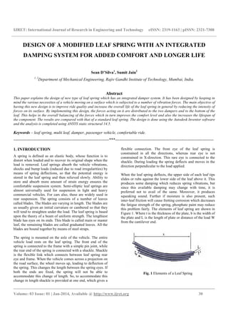
- 1. IJRET: International Journal of Research in Engineering and Technology eISSN: 2319-1163 | pISSN: 2321-7308 __________________________________________________________________________________________ Volume: 03 Issue: 01 | Jan-2014, Available @ http://www.ijret.org 30 DESIGN OF A MODIFIED LEAF SPRING WITH AN INTEGRATED DAMPING SYSTEM FOR ADDED COMFORT AND LONGER LIFE Sean D’Silva1 , Sumit Jain2 1, 2 Department of Mechanical Engineering, Rajiv Gandhi Institute of Technology, Mumbai, India. Abstract This paper explains the design of new type of leaf spring which has an integrated damper system. It has been designed by keeping in mind the various necessities of a vehicle moving on a surface which is subjected to a number of vibration forces. The main objective of having this new design is to improve ride quality and increase the overall life of the leaf spring in general by reducing the intensity of forces on its surface. By implementing this design, the forces acting on it are distributed to the two dampers and to the bottom of the leaf. This helps in the overall balancing of the forces which in turn improves the comfort level and also the increases the lifespan of the component. The results are compared with that of a standard leaf spring. The design is done using the Autodesk Inventor software and the analysis is completed using ANSYS static structural 14.5. Keywords – leaf spring, multi leaf, damper, passenger vehicle, comfortable ride. ----------------------------------------------------------------------***------------------------------------------------------------------------ 1. INTRODUCTION A spring is defined as an elastic body, whose function is to distort when loaded and to recover its original shape when the load is removed. Leaf springs absorb the vehicle vibrations, shocks and bump loads (induced due to road irregularities) by means of spring deflections, so that the potential energy is stored in the leaf spring and then relieved slowly. Ability to store and absorb more amount of strain energy ensures the comfortable suspension system. Semi-elliptic leaf springs are almost universally used for suspension in light and heavy commercial vehicles. For cars also, these are widely used in rear suspension. The spring consists of a number of leaves called blades. The blades are varying in length. The blades are us usually given an initial curvature or cambered so that they will tend to straighten under the load. The leaf spring is based upon the theory of a beam of uniform strength. The lengthiest blade has eyes on its ends. This blade is called main or master leaf, the remaining blades are called graduated leaves. All the blades are bound together by means of steel straps. The spring is mounted on the axle of the vehicle. The entire vehicle load rests on the leaf spring. The front end of the spring is connected to the frame with a simple pin joint, while the rear end of the spring is connected with a shackle. Shackle is the flexible link which connects between leaf spring rear eye and frame. When the vehicle comes across a projection on the road surface, the wheel moves up, leading to deflection of the spring. This changes the length between the spring eyes. If both the ends are fixed, the spring will not be able to accommodate this change of length. So, to accommodate this change in length shackle is provided at one end, which gives a flexible connection. The front eye of the leaf spring is constrained in all the directions, whereas rear eye is not constrained in X-direction. This rare eye is connected to the shackle. During loading the spring deflects and moves in the direction perpendicular to the load applied. When the leaf spring deflects, the upper side of each leaf tips slides or rubs against the lower side of the leaf above it. This produces some damping which reduces spring vibrations, but since this available damping may change with time, it is preferred not to avail of the same. Moreover, it produces squeaking sound. Further if moisture is also present, such inter-leaf friction will cause fretting corrosion which decreases the fatigue strength of the spring, phosphate paint may reduce this problem fairly. The elements of leaf spring are shown in Figure 1. Where t is the thickness of the plate, b is the width of the plate and L is the length of plate or distance of the load W from the cantilever end. Fig. 1 Elements of a Leaf Spring
- 2. IJRET: International Journal of Research in Engineering and Technology eISSN: 2319-1163 | pISSN: 2321-7308 __________________________________________________________________________________________ Volume: 03 Issue: 01 | Jan-2014, Available @ http://www.ijret.org 31 2. BENDING STRESS OF LEAF SPRING Leaf springs (also known as flat springs) are made out of flat plates. The advantage of leaf spring over helical spring is that the ends of the spring may be guided along a definite path as it deflects to act as a structural member in addition to energy absorbing device. Thus the leaf springs may carry lateral loads, brake torque, driving torque etc., in addition to shocks. Consider a single plate fixed at one end and loaded at the other end. This plate may be used as a flat spring. Let t = thickness of plate b = width of plate, and L = length of plate or distance of the load W from the cantilever end. We know that the maximum bending moment at the cantilever end M = W.L And section modulus, Z = Where I = (b. / 12) and Y = t/2 So Z = b. / 6 The bending stress in such a spring, f = M / Z = (6W.L) / b. ….. (1) We know that the maximum deflection for a cantilever with concentrated load at free end is given by = W. / 3.E.I = 2f. / 3.E.t ……(2) It may be noted that due to bending moment, top fibers will be in tension and bottom fibers are in compression, but the shear stress is zero at the extreme fibers and the maximum at centre, hence for analysis, both stresses need not to be taken into account simultaneously. We shall consider bending stress only. If the spring is not of cantilever type but it is like a simply supported beam, with length 2L and load2W in the centre Maximum bending moment in the centre, M = W.L Section modulus Z = b. / 6 Bending stress f = 6W.L /b. We know that maximum deflection of a simply supported beam loaded in the centre is given by = W. / 3.E.I From above we see that a spring such as automobile spring (semi-elliptical spring) with length 2L and load in the centre by a load 2W may be treated as double cantilever. If the plate of cantilever is cut into a series of n strips of width b and these are placed as shown in Figure 1, then equations (1) and (2) may be written as f = 6W.L / n.b. ………………………….. (3) = 4.W. / n.E.b. = 2.f. /3.E.t ……… (4) 2.1 Selection of Material Materials of the leaf spring should be consist of nearly 60%- 70% of the vehicle cost and contribute to the quality and the performance of the vehicle. Even a small amount in weight reduction of the vehicle, may have a wider economic impact. Composite materials are proved as suitable substitutes for steel in connection with weight reduction of the vehicle. Hence, the composite materials have been selected for leaf spring design. 2.2 Fibres Selection The commonly used fibers are carbon, glass, keviar, etc. Among these, the glass fiber has been selected based on the cost factor and strength. The types of glass fibers are C-glass, S-glass and E-glass. The C-glass fiber is designed to give improved surface finish. S-glass fiber is design to give very high modular, which is used particularly in aeronautic industries. The E-glass fiber is a high quality glass, which is used as standard reinforcement fiber for all the present systems well complying with mechanical property requirements. Thus, E-glass fiber was found appropriate for this application. 2.3 Resins Selection In a FRP leaf spring , the inter laminar shear strengths is controlled by the matrix system used. Since these are reinforcement fibers in the thickness direction, fiber do not influence inter laminar shear strength. Therefore, the matrix system should have good inter laminar shear strength characteristics compatibility to the selected reinforcement fiber. Many thermo set resins such as polyester, vinyl ester, epoxy resin are being used for fiber reinforcement plastics (FRP) fabrication. Among these resin systems, epoxies show better inter laminar shear strength and good mechanical properties. Hence, epoxide is found to be the best resins that
- 3. IJRET: International Journal of Research in Engineering and Technology eISSN: 2319-1163 | pISSN: 2321-7308 __________________________________________________________________________________________ Volume: 03 Issue: 01 | Jan-2014, Available @ http://www.ijret.org 32 would suit this application. Different grades of epoxy resins and hardener combinations are classifieds, based on the mechanical properties. Among these grades, the grade of epoxy resin selected is Dobeckot 520 F and the grade of hardener used for this application is 758. Dobeckot 520 F is a solvent less epoxy resin. This in combination with hardener 758 cures into hard resin. Hardener 758 is a low viscosity polyamine. Dobeckot 520 F, hardener 758 combinations is characterized by good mechanical and electrical properties, faster curing at room temperature and good chemical resistance properties. 2.4 Basic Design Table 1: Basic dimensions Length(L) 1000 mm Width (b) 50 mm Thickness (t) 6 mm Camber height 36 mm Shock absorber height 274.35 mm Pin hole diameter (d) 25.4 mm Fig 2: Modified leaf spring 3. ANALYSIS AND COMPARISON 3.1 Standard Leaf Spring Fig 3: Total deformation Fig 4: Equivalent elastic strain Fig 5: Maximum principal stress
- 4. IJRET: International Journal of Research in Engineering and Technology eISSN: 2319-1163 | pISSN: 2321-7308 __________________________________________________________________________________________ Volume: 03 Issue: 01 | Jan-2014, Available @ http://www.ijret.org 33 3.2 Modified Leaf Spring For the modified leaf-spring it is assumed that the load is distributed equally between the two spring and the leaf. Therefore the effective load on the leaf is taken as 5000 N. This value is taken as an average value depending on different working conditions encountered during the working cycle of the component. Fig 6: Total deformation Fig 7: Equivalent elastic strain Fig 8: Maximum principal stress Table 2: Result comparison Standard leaf spring Modified leaf spring Total deformation 0.0003 m Total deformation 0.00199 m Equivalent elastic strain 0.0023 Equivalent elastic strain 0.0023 m Maximum principal stress 3.156 x 10⁸ Pa Maximum principal stress 3.067 x 10⁸ Pa 4. RESULTS AND DISCUSSION It can be seen from the images as well as from the results obtained that the modified leaf spring is comparatively better. The stress deformation is much more uniform and hence will have a longer life and will be in turn more reliable. This also shows that it can handle a larger number of stress cycles compared to the standard leaf spring. Most of the variable forces acting on the leaf are absorbed by the dampers present and the two ends. CONCLUSIONS AND FUTURE WORK As seen from the results it can be concluded that the leaf spring with the integrated dampers is more beneficial when it comes to reliability and performance. Stress at the eye of the leaf is also relatively less as compared to the standard leaf. More analysis can be done by changing the angle at which the dampers have been positioned and it can be included in the optimization procedure of the present design. It is possible that the leaf spring with give better performance characteristics at a particular angle or at different angles relative with each other. Also variations can be carried out by changing the stiffness of the leaf as well as the damper. Hence more analysis can be carried out in the future. REFERENCES [1]. “Design &Analysis Of Mono Composite Leaf Spring”,R D V Prasad, R.Sai Srinu , P.Venkata Rao,International Journal Of Scientific Research Engineering &Technology (IJSRET),Volume 2 Issue2 Pp 103-107 May 2013 [2]. “STATIC ANALYSIS OF LEAF SPRING”,G HARINATH GOWD, International Journal Of Engineering Science And Technology (IJEST), Vol. 4 No.08 August 2012 [3]. Senthil Kumar and Vijayarangan, “Analytical and Experimental Studies On Fatigue Life Prediction Of Steel Leaf Soring And Composite Leaf Multi Leaf Spring For Light Passenger Vehicles Using Life Data Analysis” ISSN 1392 1320 Material Science Vol. 13 No.2 2007. [4]. Shiva Shankar and Vijayarangan “Mono Composite Leaf Spring For Light Weight Vehicle Design, End Joint, Analysis And Testing” ISSN 1392 Material Science Vol. 12, No.3, 2006.
- 5. IJRET: International Journal of Research in Engineering and Technology eISSN: 2319-1163 | pISSN: 2321-7308 __________________________________________________________________________________________ Volume: 03 Issue: 01 | Jan-2014, Available @ http://www.ijret.org 34 [5]. Niklas Philipson And Modelan AB “Leaf Spring Modelling” Ideon Science Park SE-22370 Lund, Sweden [6]. “Determination Of Vehicle Components Fatigue Life Based On Fea Method And Experimental Analysis”,Arif Senol Sener, International Journal Of Electronics, Mechanical And Mechatronics Engineering Vol.2 Num.1 Pp.(133-145) [7]. “Performance Analysis Of Two Mono Leaf Spring Used For Maruti 800 Vehicle”, Jadhav Mahesh V, Zoman Digambar B, Y R Kharde, R R Kharde, International Journal Of Innovative Technology And Exploring Engineering (IJITEE) ISSN: 2278-3075, Volume-2, Issue-1, December 2012 [8]. Shiva Shankar And Vijayarangan “Mono Composite Leaf Spring For Light Weight Vehicle Design, End Joint, Analysis And Testing” ISSN 1392 Material Science Vol. 12, No.3, 2006.