Downloaded 281 times
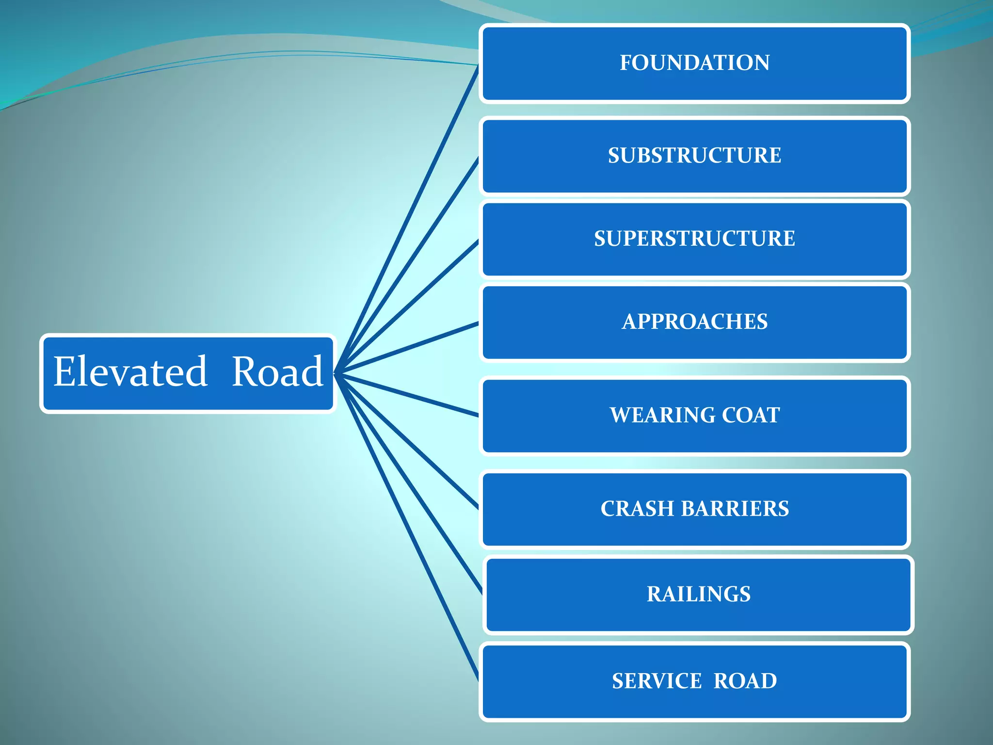
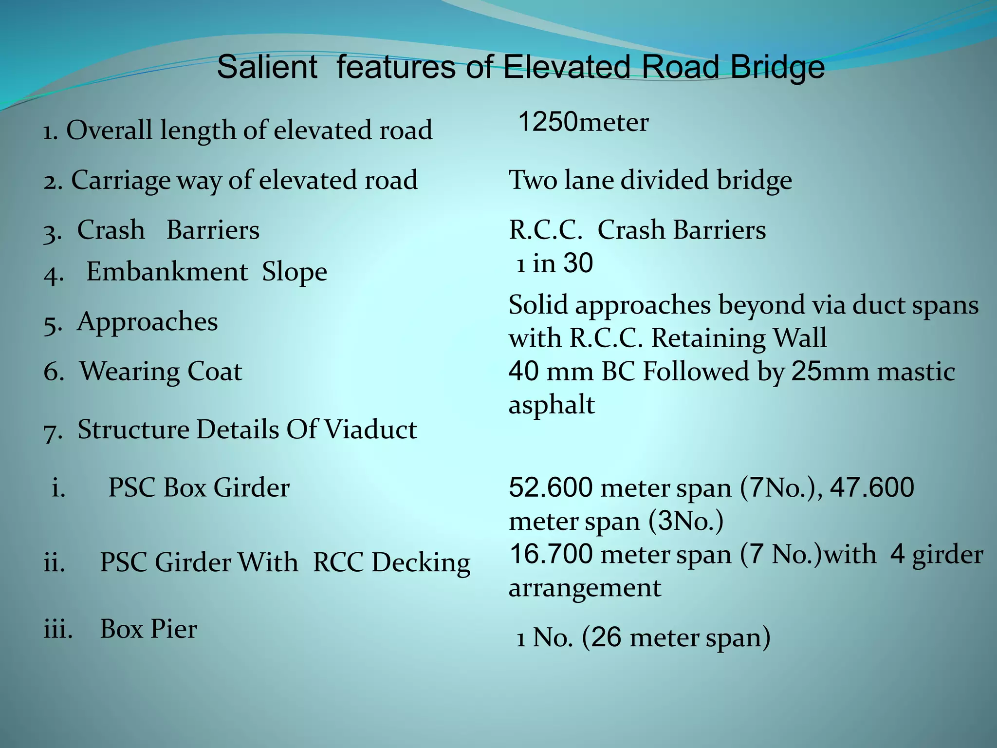
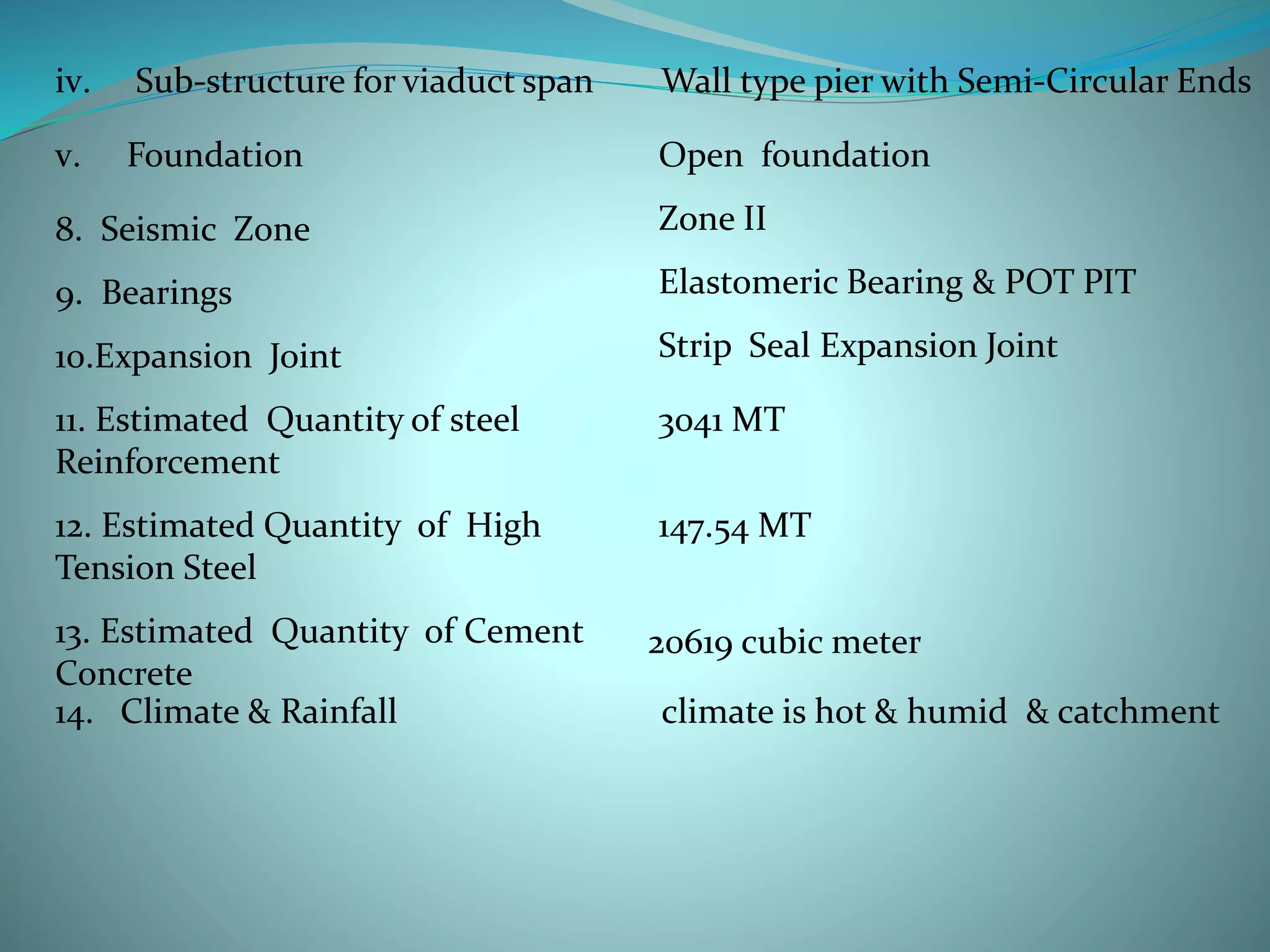
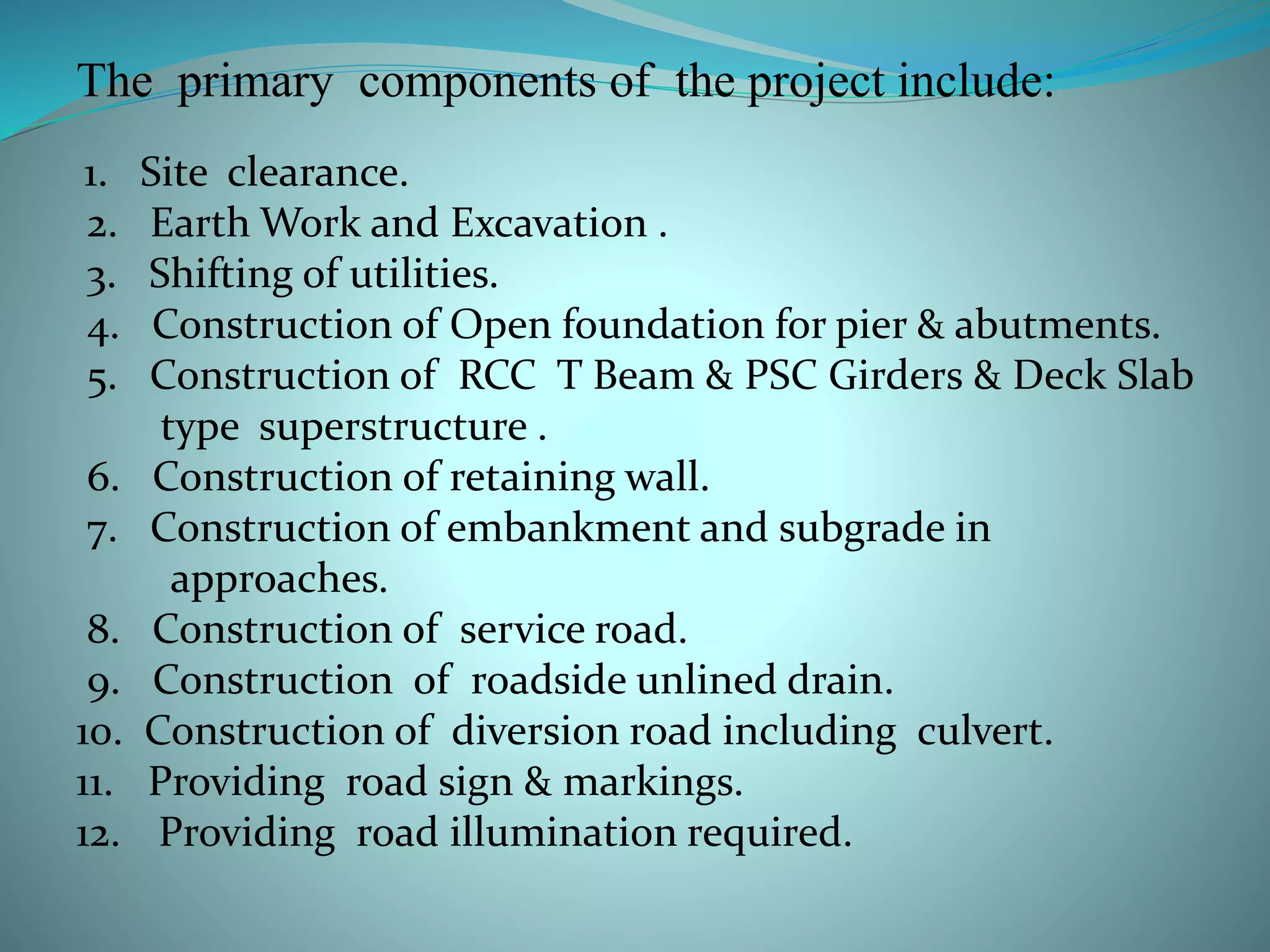
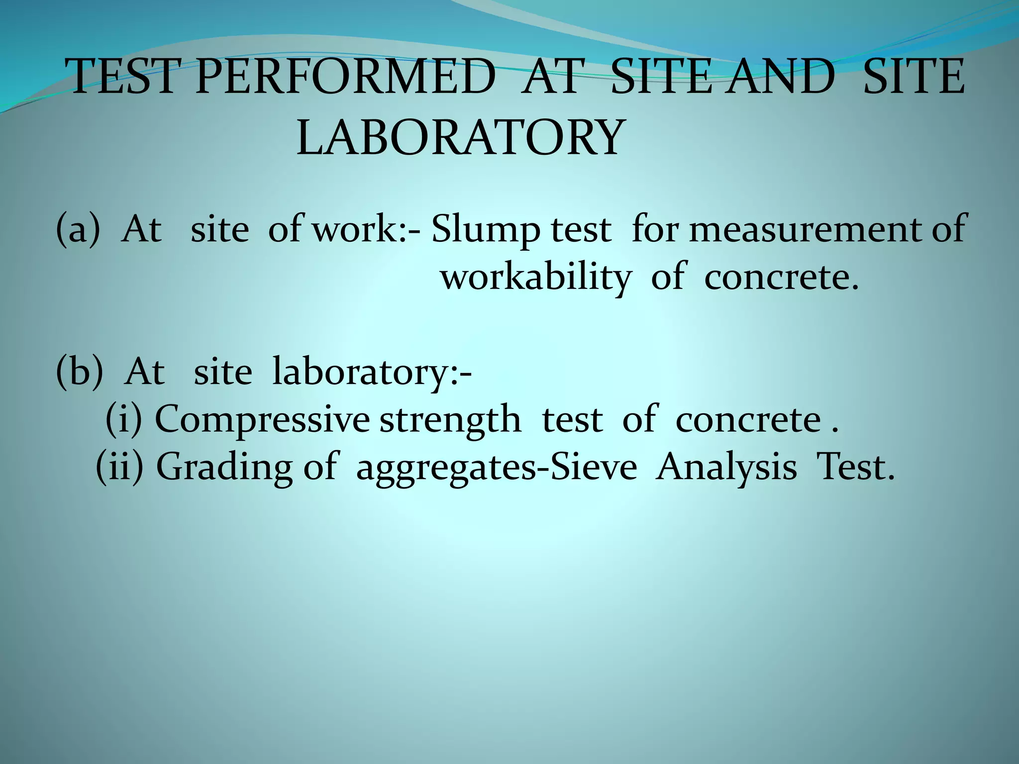
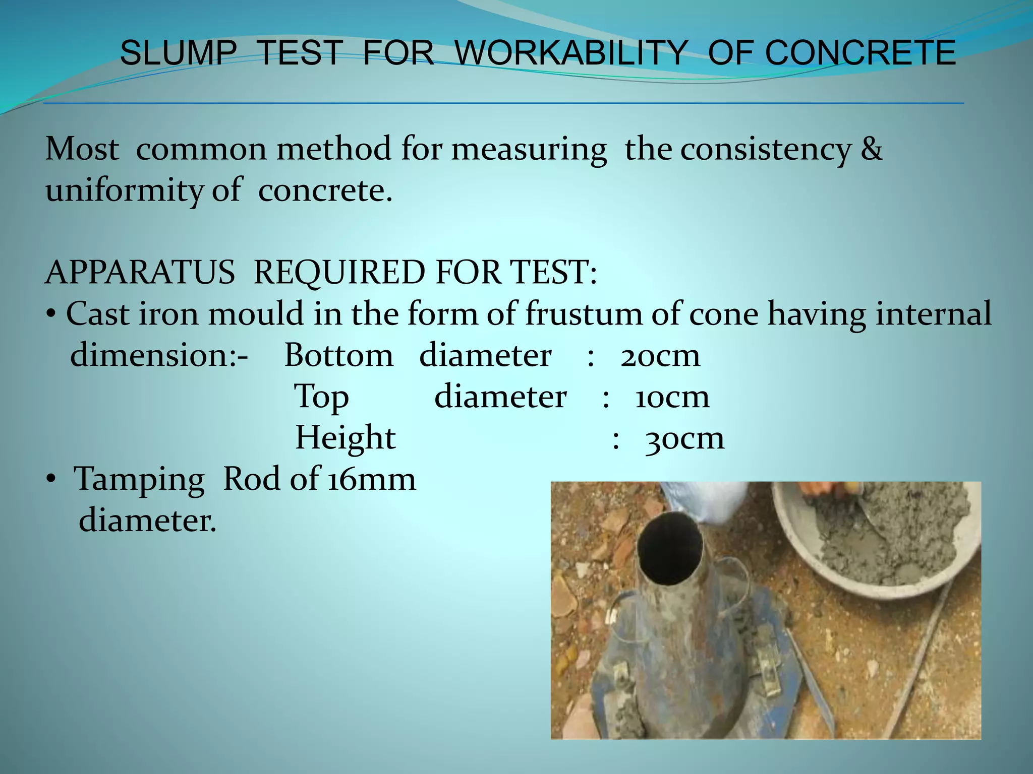

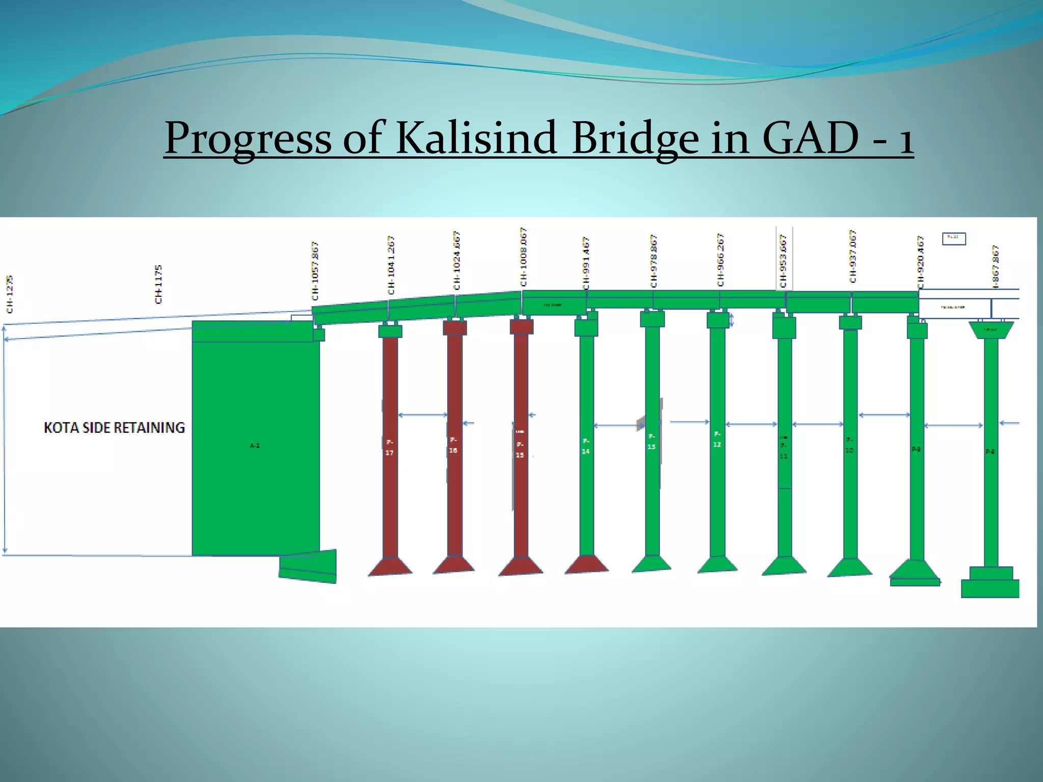
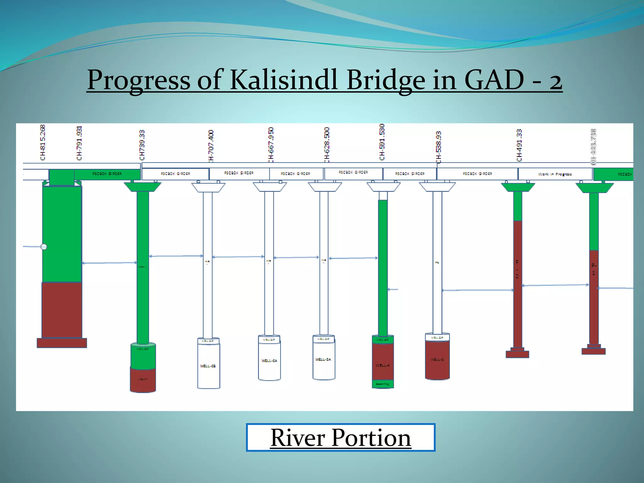
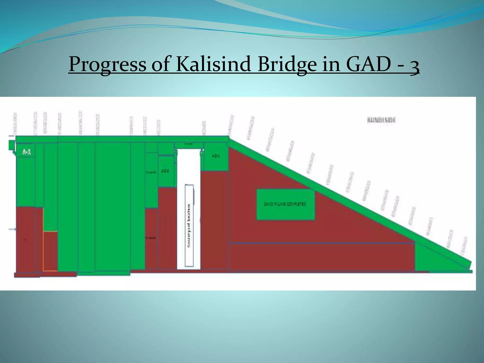


This presentation summarizes the key aspects of an elevated road project in India. It includes three main points: 1. The elevated road project has a total length of 1250 meters with two lanes, crash barriers along the sides for safety, and approaches built with retaining walls. 2. The main components of the project are site clearance, earthworks, construction of foundations for piers and abutments, building the superstructure with pre-stressed concrete girders and deck slabs, and construction of service roads. 3. Testing was performed on site to check the workability and strength of concrete used in building the foundations, piers, and other structural elements. Slump tests were used to


